Skyjack SJ46AJ Operating Manual
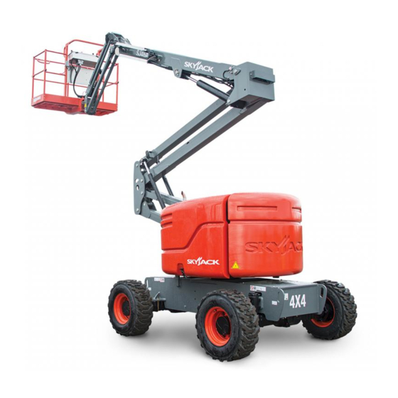
Articulating booms
Hide thumbs
Also See for SJ46AJ:
- Parts manual (300 pages) ,
- Operating manual (120 pages) ,
- Operating manual (95 pages)

Related Manuals for Skyjack SJ46AJ


Summary of Contents for Skyjack SJ46AJ
- Page 1 OPERATING MANUAL (CE) ARTICULATING BOOMS MODELS SJ46AJ SJ51AJ 170493AFA April 2019...
- Page 2 This manual is based on Serial Number(s): SJ46AJ/SJ51AJ & Above 95 001 105 SJ46AJ/SJ51AJ B301 000 001 & Above Please refer to the website (www.skyjack.com) for older Serial Numbers. Skyjack Service Center Parts & Service (Europe) Unit 1 Maes Y Clawdd 3451 Swenson Ave. St. Charles,...
- Page 3 The Safety Alert Symbol identifies important safety messages on MEWP , safety signs in This Safety Alert Symbol means attention! manuals or elsewhere. When you see this symbol, be alert to the possibility of personal Become alert! Your safety is involved. injury or death.
-
Page 4: Table Of Contents
Table of Contents Section 1 - About Your MEWP ........................ 5 Read and Heed ..............................5 Safety Rules ................................6 Section 2 - Familiarization ..........................11 Familiarization of Articulated Boom Series ....................11 Component Identification ..........................12 2.2-1 Main Power Disconnect Switch & Battery Charge Indicator ............12 2.2-2 Tilt Sensor ............................12 2.2-3... -
Page 5: Section 1 - About Your Mewp
SKYJACK warrants each new articulating series work platform to be free of defective parts and workmanship for the first 24 months. Any defective part will be replaced or repaired by your local SKYJACK dealer at no charge for parts or labor. Contact the SKYJACK Service Department for warranty statement extensions or exclusions. -
Page 6: Safety Rules
Common sense dictates the use of protective clothing when working on or near machinery. Use appropriate safety devices to protect your eyes, ears, hands, feet and body. Any modifications from the original design are strictly forbidden without written permission from SKYJACK. Electrocution Hazard This MEWP is not electrically insulated. - Page 7 Section 1 - About Your Aerial Platform Safety Rules Safety Precautions Know and understand the safety precautions before going on to next section. WARNING DO NOT • increase the lateral Failure to heed the following safety surface area of the platform. precautions could result in tip over, Increasing the area exposed to falling, crushing, or other hazards leading...
- Page 8 Safety Rules Section 1 - About Your Aerial Platform Safety Precautions (Continued) Know and understand the safety precautions before going on to next section. • DO NOT operate an MEWP • BE AWARE of blind spots when that has ladders, scaffolding or operating the MEWP .
- Page 9 MEWP . object to steady the platform. • DO NOT place materials on the guardrails or materials that exceed the confines of the guardrails unless approved by Skyjack. • distribute load • DO NOT operate if MEWP is unevenly.
- Page 10 Know and understand the safety precautions before going on to next section. Fall Protection WARNING An operator should not use any MEWP that: Skyjack recommends the use of a fall restraint system to keep an occupant within the confines • does not appear to be working properly.
-
Page 11: Section 2 - Familiarization
Section 2 - Familiarization SJ AJ Series 2.1 Familiarization of Articulated Boom Series WARNING MEWP Familiarization should be given only to individuals who are QUALIFIED and TRAINED to operate an MEWP . Do not operate this MEWP without proper authorization and training. Failure to avoid this hazard could result in death or serious injury. -
Page 12: Component Identification
Control Functions Section 2 - Familiarization 2.2 Component Identification 2.2-3 Drive Bypass Valve The following descriptions are for identification, This valve is located on the inboard side of the drive explanation and locating purposes only. pump and can be identified with a yellow paint mark on it. -
Page 13: Differential Lock Switch
Section 2 - Familiarization Control Functions 2.2-5 Differential Lock Switch This switch is located on the platform control console. The differential locking system provides more traction by providing equal drive to each wheel regardless of traction. Differential locks are used to prevent from getting stuck when driving on loose, muddy, or rocky terrrain. -
Page 14: 7A Platform Load Sensing System
Control Functions Section 2 - Familiarization 2.2-7a Platform Load Sensing System The platform load sensing system is a device that senses for an overload on the platform before the system disables boom and drive functions. This system is active when MEWP is powered on. If the platform is overloaded while in work mode (boom is raised greater than 15 degrees from horizontal or is extended greater than 6 inches), the load sensing system will disable all normal functions and signal the operator with an indicator light and an audible alarm. - Page 15 Notes SJ 46AJ & SJ 51AJ December 2007 Page 15...
- Page 16 Control Functions Section 2 - Familiarization 2.2-8 Base Control Console This control console is located in the panel mounted in the control compartment. HOUR METER COUNTER QUARTZ Figure 2-5. Base Control Console Base/Off/Platform Key Switch - This three-way Start/Function Enable/Emergency Power Switch - This momentary switch, when held in selector switch allows operator to “...
- Page 17 Section 2 - Familiarization Control Functions 2.2-8 Base Control Console (Continued) HOUR METER COUNTER QUARTZ Figure 2-5. Base Control Console Platform Leveling Override Switch - This switch Circuit Breakers - In the event of a power overload overrides automatic leveling of platform and or positive circuit grounding, the circuit breaker pops out.
- Page 18 Control Functions Section 2 - Familiarization 2.2-9 Platform Control Console This control console is mounted at front guardrail of the platform. It has the following controls: EMERGENCY LOWERING PROCEDURE At Platform Controls: 1. Pull out emergency stop button. 2. Depress and hold foot switch. 3.
- Page 19 Section 2 - Familiarization Control Functions 2.2-9 Platform Control Console (Continued) EMERGENCY LOWERING PROCEDURE At Platform Controls: 1. Pull out emergency stop button. 2. Depress and hold foot switch. 3. Activate emergency pump switch. 4. Activate desired boom function. 149432AA 149432AA Figure 2-6.
-
Page 20: Visual & Daily Maintenance Inspections
Visual & Maintenance Inspection Section 2 - Familiarization Platform Platform Control Railing Console Manual Box Footswitch Platform Assembly 2.3 Visual & Daily Maintenance Inspections 2.3-2 Electrical Maintaining the electrical components is essential to Begin the visual and daily maintenance inspections good performance and service life of the MEWP . - Page 21 Section 2 - Familiarization Visual & Maintenance Inspection Main Power Muffler and Disconnect Switch Exhaust Battery Charge Indicator Air Filter High Pressure Filter Limit Switch 2.3-5 Engine Compartment 1. Check battery cases for damage. Ensure all compartment latches are secure and in proper working order.
- Page 22 Visual & Maintenance Inspection Section 2 - Familiarization Main Power Muffler and Disconnect Switch Exhaust Battery Charge Indicator Air Filter High Pressure Filter Limit Switch • Hydraulic Pumps Check oil level on dipstick Ensure there are no loose or missing Oil level should be in the “safe”...
- Page 23 Section 2 - Familiarization Visual & Maintenance Inspection Brake Manifold Main Manifold Base Control Console Hydraulic Tank Fuel Tank Emergency Power Unit 2.3-6 Control Compartment • Emergency Power Unit Ensure all compartment latches are Ensure there are no loose or missing secure and in proper working order.
- Page 24 Visual & Maintenance Inspection Section 2 - Familiarization Overhead View Tie Rod Oscillating Cylinder Turret Rotation Assembly Gear Drive Axle Wheel/Tire Assembly Steer Cylinder Assembly • Fuel Leaks • Oscillating Cylinder Assembly Ensure that there no fuel leaks. Ensure oscillating cylinder assembly is properly secured, there are no loose DANGER or missing parts, all fittings and hoses...
- Page 25 Therefore, 2.3-10 Platform Control Console replace tires only with the exact Skyjack- Ensure all switches/controllers are returned approved type. Failure to operate with to neutral and are properly secured. matched approved tires in good condition may result in death or serious injury.
- Page 26 Visual & Maintenance Inspection Section 2 - Familiarization Wear Pads Main and Fly Booms Power Track Riser Rotary Actuator Cylinders Load Cell 2.3-11 Rotary Actuator 2.3-14 Boom Ensure there are no loose or missing parts Ensure there are no loose or missing parts and there is no visible damage.
- Page 27 Section 2 - Familiarization Visual & Maintenance Inspection Work Light 2.3-15 Optional Equipment/Attachments • Battery Warmer/Hydraulic Oil Heater (If Equipped) Ensure battery warmer/hydraulic oil heater cord is properly secured with no signs of visible damage and hydraulic leakage. • Flashing Amber Light (If Equipped) Ensure lamp is properly secured with no signs of visible damage.
-
Page 28: Function Tests
Function Tests Section 2 - Familiarization Main Power Muffler and Disconnect Switch Exhaust Battery Charge Indicator Air Filter High Pressure Filter Limit Switch 2.4 Function Tests Function tests are designed to discover any malfunctions WARNING before MEWP is put into service. The operator must Cold Weather - Caution must be understand and follow step-by-step instructions to test exercised when operating MEWP in... - Page 29 Section 2 - Familiarization Function Tests Base Control Console Base/Off/Platform Key Switch HOUR METER Emergency COUNTER Stop QUARTZ Start/Function Enable/ Emergency Power Switch 2.4-1 Test Main Power Disconnect Switch NOTE Close all cowlings before proceeding to In engine compartment, turn main power next item.
- Page 30 Function Tests Section 2 - Familiarization Base Control Console Base/Off/Platform Key Switch HOUR METER Emergency COUNTER Stop QUARTZ Start/Function Enable/ Emergency Power Switch • Test Base Emergency Stop • Test Platform Self-leveling 1. Lower boom to stowed position. 1. Push in “ ”...
- Page 31 Section 2 - Familiarization Function Tests Base Control Console Base/Off/Platform Key Switch HOUR METER Emergency COUNTER Stop QUARTZ Start/Function Enable/ Emergency Power Switch NOTE • Test Base/Off/Platform Switch To conserve battery power, test each function through a partial cycle. 1. Ensure both “ ”...
- Page 32 Function Tests Section 2 - Familiarization Drive/Steer Controller Emergency Stop Platform Control Platform Railing Console Manual Box Tie-off Point Tie-off Point Footswitch Footswitch Platform Platform Assembly Assembly 7. Select “ ” start position from engine WARNING start/on/off switch to start engine. DO NOT operate any control on platform control console without proper fall 8.
- Page 33 Section 2 - Familiarization Function Tests Drive/Steer Controller Emergency Stop Platform Control Platform Railing Console Manual Box Tie-off Point Tie-off Point Footswitch Footswitch Platform Platform Assembly Assembly • Test Platform Emergency Stop 6. Without depressing footswitch, try to start engine. Result: Engine should start.
- Page 34 Function Tests Section 2 - Familiarization Engine start/on/off Emergency Power Switch Horn Switch Drive/Steer Controller • Test Engine Start/On/Off Switch • Test Driving Function 1. Ensure engine is running. 1. Ensure path of intended motion is clear. 2. Ensure boom is in stowed position and fly 2.
- Page 35 Section 2 - Familiarization Function Tests Engine start/on/off Emergency Power Switch Horn Switch Drive/Steer Controller • Test Driving Speed • Test Load Sensing System 1. Depress and hold footswitch. 1. Push in “ ” emergency stop button. 2. Pull out “ ”...
- Page 36 Function Tests Section 2 - Familiarization Engine start/on/off Emergency Power Switch Horn Switch Drive/Steer Controller • Test Emergency Power 5. Select “ ” from emergency power unit switch and activate each function CAUTION control handle or switch. Result: All boom and steer functions When operating on auxiliary power, do should operate.
- Page 37 Section 2 - Familiarization Function Tests Engine start/on/off Emergency Power Switch Horn Switch Drive/Steer Controller • Test Brakes 2. On platform leveling override switch, pull and select “ ” up position to tilt WARNING platform up or “ ” down position Brakes will engage instantly when you release footswitch, causing MEWP to to tilt platform down.
- Page 38 Function Tests Section 2 - Familiarization Oscillating Axle - Locked Oscillating Axle - Unlocked • Test Oscillating Axles WARNING DO NOT operate any control on platform control console without proper fall protection secured to designated location in platform. Failure to avoid this hazard could result in death or serious injury! 1.
-
Page 39: Winching And Towing Procedure
Section 2 - Familiarization Procedures 2.5 Winching and Towing Procedure Position MEWP on a firm and level surface. This section provides the operator with the Winching and Towing procedure, which includes instructions on Chock or block wheels to prevent MEWP from how to manually release the brakes. - Page 40 Procedures Section 2 - Familiarization 2.5-1 To Release Brakes Manually CAUTION Brakes must be manually disengaged for winching or Do not release brakes before disengaging towing. drive motor! WARNING Push in black brake valve plunger (item 2). Do not manually disengage brakes if MEWP is on a slope.
-
Page 41: Emergency Lowering Procedures
Section 2 - Familiarization Procedures 2.6 Emergency Lowering Procedures At Platform Control Console: This section guides the operator on how to use Ensure engine is off. emergency lowering system. This system allows platform lowering in the event of an emergency or engine malfunction. - Page 42 Notes SJ 46AJ & SJ 51AJ Page 42 December 2007...
-
Page 43: Section 3 - Operation
Section 3 - Operation General 3.0 Operation • The operator must be sure that the MEWP has This section provides the necessary information needed been properly maintained and inspected before to operate the MEWP . It is important that the user reads using it. -
Page 44: Major Components
Section 3 - Operation 3.2 Major Components Platform Control Console Fly Boom Platform Main Boom Power Track Lift Cylinder Riser Riser Control Cylinders Compartment Base Control Engine Console Compartment Turret Base SKYJACK Articulating Boom SJ 46AJ & SJ 51AJ Page 44 December 2007... -
Page 45: Major Assemblies
Section 3 - Operation Major Assemblies 3.3 Major Assemblies 3.4 Serial Number Nameplate The MEWP consists of four major assemblies: the base, The serial number nameplate, located at the rear of the turret, boom assembly and platform. MEWP , lists the following: •... -
Page 46: Component Identification
Component Identification Operation - Section 3 3.5 Component Identification 3.5-4 Turret Transportation Lock This locking device is located in the turret. The following descriptions are for identification, explanation and locating purposes only. 3.5-1 Manual Storage Box This weather-resistant box is mounted under the control console on the platform. -
Page 47: Component Identification (Optional Equipment/Attachments)
Section 3 - Operation Component Identification 3.6 Component Identification (Optional Equipment/Attachments) The following descriptions are for identification, explanation and locating purposes only. 3.6-1 Cold Weather Start (If Equipped) The battery warmer/hydraulic oil heater cord is located on the engine compartment near the battery. This cord is plugged into the AC outlet at least 4 hours before starting engine when temperature gets below -10°C (+14°F). -
Page 48: Operator's Responsibility
Operator’s Responsibility Section 3 - Operation 3.7 Operator’s Responsibility 3. Cold Weather Hydraulic System Warm Up It is the responsibility of the operator, prior to each work shift, to perform the following: WARNING Caution must be exercised when 1. Visual and Daily Maintenance Inspections operating MEWP in cold temperature. -
Page 49: Start Operation
Section 3 - Operation Start Operation 3.8 Start Operation 3.8-1 To Activate Base Control Console Carefully read and completely understand the Operating Manual and all warnings and instruction labels WARNING (refer to Section 5 - Labels) on the MEWP . Ensure that you maintain three points of contact to mount/dismount the platform. - Page 50 Start Operation Section 3 - Operation 3.8-3 To Rotate Turret Using Base Control 3.8-6 To Raise or Lower Main Boom Using Base Console Control Console WARNING Activate and hold function enable switch “ ” by pushing it to the right. When rotating the turret, ensure that there are no personnel or obstructions in the Push main boom raise/lower switch to either...
- Page 51 Section 3 - Operation Start Operation 3.8-9 To Operate Using Emergency Power On platform control console, pull out “ ” Switch at Base Control Console emergency stop button. This is a momentary-type switch. This switch allows Push and hold “ ”...
- Page 52 Start Operation Section 3 - Operation 3.8-11 To Drive Forward or Reverse 3.8-12 To Steer Depress and hold footswitch. CAUTION When you are in the platform and Press rocker on top of drive/steer controller in this positioned over an axle, the direction you are facing will be forward.
- Page 53 Section 3 - Operation Start Operation 3.8-16 To Rotate Platform Using Platform 3.8-20 To Rotate Turret Using Platform Control Control Console Console Depress and hold footswitch. WARNING When rotating the turret, ensure that there On platform rotation switch, select “ ” to rotate are no personnel or obstructions in the path of rotation, including blind spots.
- Page 54 Start Operation Section 3 - Operation 3.8-22a To Engage Differential Lock Switch 3.8-24 Hydraulic Generator (If Equipped) Depress and hold footswitch. To start hydraulic generator: On platform control console, push differential lock Ensure engine is running. switch forward “ ” to the locked position and On platform control console, turn generator on/ then release.
-
Page 55: Refueling Procedure
Section 3 - Operation Refueling Procedure 3.9 Refueling Procedure 3.9-1 Regular Fuel (Diesel) This section provides the operator with procedure on IMPORTANT how to refuel engine with regular fuel. Use unleaded gasoline only. WARNING Ensure engine and all systems are turned off and Failure to heed the following safety emergency stop buttons are depressed. -
Page 56: Loading/Unloading
Loading/Unloading Section 3 - Operation 3.10 Loading/Unloading Turn main power disconnect switch to “ ” off Know and heed all national, state/provincial and local position. rules which apply to transporting of MEWPs. Chock MEWP wheels (if necessary). Only qualified personnel shall operate MEWP during loading/unloading. - Page 57 Section 3 - Operation Loading/Unloading 3.10-2 Locking the Turret WARNING Use chains of ample load capacity Ensure that turret is positioned so that turret sufficient to withstand MEWP weight. transportation lock tube (item 1 - Figure 3-3) is aligned into one of two turret locking points in the Place boom in stowed position centered turret rotation lock plate.
-
Page 58: Chassis Tilt
Chassis Tilt Section 3 - Operation 3.11 Chassis Tilt 3.11-1 Platform Uphill If the MEWP becomes tilted with the platform uphill This section guides the operator with regard to (refer to Figure 3-4) follow the steps below to return to recovering from an inclined position. - Page 59 Section 3 - Operation Diagrams Diagram 3.1 Dimension and Reach Diagram - SJ 46AJ Meters 16.76 15.24 13.72 12.19 10.67 9.14 7.62 6.10 4.57 3.05 1.52 1.52 Figure 3-6. Reach Diagram - 46AJ 1.50 M 178° 4.34 M 75° 0.76 M 45°...
- Page 60 Diagrams Section 3 - Operation Diagram 3.2 Dimension and Reach Diagram - SJ 51AJ Meters 13.72 7.62 4.57 3.05 1.52 1.52 3.05 Figure 3-8. Reach Diagram - 51AJ 1.50 M 178° 4.34 M 0.76 M 45° 2.29 M 1.83 M 2.86 M 9.03 M 17.55 M...
- Page 61 Section 3 - Operation Diagrams Diagram 3.3 Axle Oscillation Diagram WARNING Do not raise the platform in work mode if it is not on a firm level surface. Axle oscillation free (travel mode) - drive speed 7.7 km/h (4.8 mph) max. Axle oscillation locked (work mode) - drive speed 0.8 km/h (0.5 mph) max.
- Page 62 Notes SJ 46AJ & SJ 51AJ Page 62 December 2007...
-
Page 63: Section 4 - Tables
Section 4 Tables Table 4.1 Standard and Optional Features MODEL SJ 46AJ SJ 51AJ S T A N D A R D E Q U I P M E N T 12-Volt DC emergency power 5-foot jib ... -
Page 64: Table 4.2A Specifications And Features
Tables Section 4 Table 4.2a Specifications and Features MODEL SJ 46AJ SJ51AJ Total platform length (outside) 152 cm/ 183 cm 152 cm/ 183 cm Total platform depth (outside) 76 cm 76 cm Working 16.1 m 17.6 m Platform elevated 14.1 m 15.6 m Drive Driveable at all heights... -
Page 65: Table 4.2B Specifications And Features
200°F (+93°C) Temperature Approved Alternates Chevron Rykon MV (Note: Cold weather starting temperatures can be improved Mobilfluid 424 with Skyjack options. Please consult your nearest Skyjack Esso Univis N46 service center.) Hydraulic Tank Capacity 91 L Sound Pressure Level (ISO 3744) -
Page 66: Table 4.3 Owner's Annual Inspection Record
Tables Section 4 Table 4.3 Owner’s Annual Inspection Record Model Number: _________________ Serial Number:__________________ 20__ 20__ 20__ 20__ 20__ 20__ 20__ 20__ 20__ 1001AB This decal is located on the control compartment cowling. It must be completed after an annual inspection has been completed. -
Page 67: Table 4.4 Tire/Wheel Specifications
Section 4 Tables Table 4.4 Tire/Wheel Specifications SJ 46AJ SJ 51AJ Tire Size 30.5 cm x 41.9 cm 30.5 cm x 41.9 cm Type Foam-filled Foam-filled Tire Ply Rating Wheel Nuts Torque 393.2 Nm 393.2 Nm 60639AC-CE IMPORTANT For proper function of each axle differential, all four wheels must have same tire size installed at all times. -
Page 68: Table 4.6 Floor Loading Pressure
Intermixing tires of different types or using tires of types other than those originally supplied with this equipment can adversely affect stability. Therefore, replace tires only with the exact Skyjack- approved type. Failure to operate with matched approved tires in good condition may result in death or serious injury. -
Page 69: Table 4.7 Maintenance And Inspection Schedule
B - Perform Scheduled Maintenance Inspection. Refer to Service & Maintenance manual. * - Maintenance must be performed only by trained and competent personnel who are familiar with mechanical procedures. † - Refer to Skyjack's website @ www.skyjack.com for latest service bulletins prior to performing quarterly or yearly inspection. -
Page 70: Table 4.8 Operator's Checklist
Model: Hourmeter Reading: Operator's Name (Printed): Date: Time: Operator's Signature: Each item shall be inspected using the appropriate section of the Skyjack operating manual. As each item is inspected, check the appropriate box. INSPECTION FREQUENCY - PASS DAILY - FAIL FREQUENTLY ... -
Page 71: Section 5 - Labels
Section 5 - Labels Label Legend Label Legend Safety Red Safety Red indicates DANGER. Safety Orange Safety Orange indicates WARNING. Safety Yellow Safety Yellow indicates CAUTION. Safety Green Safety Green indicates emergency lowering. Safety Blue Safety Blue indicates safety information. SJ 46AJ &... - Page 72 Labels Section 5 Engine Side Label Pictorial Description Connect AC Supply Connect AC supply here. Body Crushing Hazard Danger - Body crushing hazard Tie Down Points Only use these points for tying down. Crushing Hazard Danger - Crushing hazard SJ 46AJ & SJ 51AJ Page 72 December 2007...
- Page 73 Engine Side (Continued) Label Pictorial Description Warning - Do Not Alter Do not alter or disable limit switches or other safety devices. Skyjack Logo Skyjack Model Number* Product Identifier *Model number will vary, may not be as shown. SJ 46AJ & SJ 51AJ...
- Page 74 Labels Section 5 Engine Compartment Label Pictorial Description Winching/Towing/Pushing Procedure Refer to Operating manual. 1. Block or chock wheels to prevent MEWP from rolling. 2. Turn main power disconnect switch to off position. At engine side: 3. Locate bypass valve (marked with yellow colour) on inboard side of drive pump.
- Page 75 Section 5 Labels Engine Compartment (Continued) Label Pictorial Description Lift and Tie Down Points Only use these points for lifting or tying down. Wheel Specifications Refer to manual for wheel type, offset, pressure and torque. Wheel Load* Indicates rated wheel load. *Wheel load will vary over different MEWPs.
- Page 76 Labels Section 5 Engine Compartment (Continued) Label Pictorial Description Foam-filled Tire Indicates foam-filled tire. Sound Power Level Guaranteed maximum sound power level “CE” CE rating mark Main Power Disconnect Main power disconnect lever Warning - Do Not Alter Do not alter or disable limit switches or other safety devices. SJ 46AJ &...
- Page 77 Section 5 Labels Rear Side - Base Label Pictorial Description 4x4 (If Equipped) Product identifier - 4 wheel drive Serial Plate* Product identification and specifications *Serial plates will vary, may not be as shown. SJ 46AJ & SJ 51AJ December 2007 Page 77...
- Page 78 Labels Section 5 Control Compartment Label Pictorial Description Winching/Towing/Pushing Procedure Refer to Operating manual. 1. Block or chock wheels to prevent MEWP from rolling. 2. Turn main power disconnect switch to off position. At engine side: 3. Locate bypass valve (marked with yellow colour) on inboard side of drive pump.
- Page 79 Section 5 Labels Control Compartment (Continued) Label Pictorial Description Hydraulic Oil Level Indicates minimum/maximum oil level. Lift and Tie Down Points Only use these points for lifting or tying down. Wheel Specifications Refer to manual for wheel type, offset, pressure and torque. Wheel Load* Indicates rated wheel load.
- Page 80 Labels Section 5 Control Compartment (Continued) Label Pictorial Description Foam-filled Tire Indicates foam-filled tire. Sound Power Level Guaranteed maximum sound power level “CE” CE rating mark No Smoking Do not smoke near this location. Diesel Use diesel fuel only. Grease Points Maintenance Refer to service and maintenance manual for lubricating “...
- Page 81 Section 5 Labels Control Compartment (Continued) Label Pictorial Description Base Control Console P u s h “ ” b r e a k e r b a c k i n t o r e s e t . S e l e c t a n d h o l d “...
- Page 82 Labels Section 5 Control Side Label Pictorial Description Body Crushing Hazard Danger - Body crushing hazard Annual Inspection Ensure that work platform has received annual inspection prior to operation. Emergency Lowering Procedure In case of emergency, follow procedure outlined in label to lower the platform.
- Page 83 Control Side (Continued) Label Pictorial Description Tie Down Points Only use these points for tying down. Model Number* Product Identifier *Model number will vary, may not be as shown. Skyjack Logo Skyjack SJ 46AJ & SJ 51AJ December 2007 Page 83...
- Page 84 Labels Section 5 Platform Label Pictorial Description Platform Capacity - Operating on Level Ground* Rated work load when operating on a level ground. Rated work load includes the weight of both personnel and material, and maximum number of people in each configuration. Do not exceed total weight or maximum number of people.
- Page 85 Section 5 Labels Platform (Continued) Label Pictorial Description Warning - No Step No step warning Harness Anchorage Anchor safety belt/harness tethers here. Manual Box Indicates location of operating manual. Platform Capacity - Operating on Level Ground* Rated work load when operating on a level ground. Rated work load includes the weight of both personnel and material, and maximum number of people in each configuration.
- Page 86 Model Number* Product Identifier *Model number will vary, may not be as shown. Horizontal Load Rating Apply no more than indicated side load. Operate below indicated wind speed only. Skyjack Logo Skyjack SJ 46AJ & SJ 51AJ Page 86 December 2007...
- Page 87 Section 5 Labels Platform (Continued) Label Pictorial Description Crushing Hazard Danger - Crushing hazard Warning - Do Not Alter Do not alter or disable limit switches or other safety devices. Footswitch Enable (On/Off) Depress and hold footswitch to enable platform function. SJ 46AJ &...
- Page 88 Labels Section 5 Platform Control Console EMERGENCY LOWERING PROCEDURE At Platform Controls: 1. Pull out emergency stop button. 2. Depress and hold foot switch. 3. Activate emergency pump switch. 4. Activate desired boom function. 149432AA 149432AA Label Pictorial Description Glow Plugs/Start Engine Select “...
- Page 89 Section 5 Labels Platform Control Console (Continued) EMERGENCY LOWERING PROCEDURE At Platform Controls: 1. Pull out emergency stop button. 2. Depress and hold foot switch. 3. Activate emergency pump switch. 4. Activate desired boom function. 149432AA 149432AA Label Pictorial Description Boom/Turret Controller Push and hold controller in this direction “...
- Page 90 Labels Section 5 Front Side - Base Label Pictorial Description Body Crushing Hazard Danger - Body crushing hazard Serial Plate* Product identification and specifications *Serial plates will vary, may not be as shown. 4x4 (If Equipped) Product identifier - 4 wheel drive Connect AC Supply Connect AC supply here.
- Page 92 www.skyjack.com...
Need help?
Do you have a question about the SJ46AJ and is the answer not in the manual?
Questions and answers