Table of Contents
Advertisement
Quick Links
Advertisement
Table of Contents

Related Manuals for Fujitsu m2488


Summary of Contents for Fujitsu m2488
- Page 1 C144-E018-03EN M2488 CARTRIDGE TAPE DRIVE USER’S GUIDE...
- Page 2 The contents of this manual may be revised without prior notice. The contents of this manual shall not be disclosed in any way or reproduced in any media without the express written permission of Fujitsu Limited. All Rights Reserved, Copyright © FUJITSU LIMITED 1996, 1997 C144-E018-03EN...
-
Page 3: Revision History
M2488 USER’S GUIDE REVISION HISTORY REVISION HISTORY (1/1) Revised Section Edition Date Details (Added/Deleted/Altered) 1996-03-06 — — 1996-06-12 Totally revised — 1997-04-03 Totally revised — Sections with an asterisk (*) refer to the deleted parts in the previous edition. C144-E018-03EN... -
Page 5: Directory
International Marketing Marunouchi 1-6-1, Chiyoda-ku, Tokyo 100 JAPAN TEL: 03-216-3211 FAX: 03-213-7174, 03-216-9353 TLX: J22833 Cable: “FUJITSU LIMITED TOKYO” FUJITSU COMPUTER PRODUCTS OF AMERICA, INC. 2904 Orchard Parkway, San Jose, California 95134-2017 USA TEL:1-408-432-6333 FAX: 408-894-1709 TLX: 230-176207 TWX: 910-338-2193 FUJITSU CANADA, INC. -
Page 7: Agency Statements
Important: Changes or modifications to this product not authorized by Fujitsu Computer Products of America, Inc. could void the FCC Certification and negate your authority to operate the product. -
Page 9: Preface
M2488 USER’S GUIDE PREFACE PREFACE The M2488 User’s Guide provides the information necessary for the user to operate the M2488 Car- tridge Tape Drive. Chapter 1 Introduction This chapter provides an overview of the M2488 Cartridge Tape Drive and its optional equipment. -
Page 11: Table Of Contents
M2488 USER’S GUIDE TABLE OF CONTENTS TABLE OF CONTENTS CHAPTER TITLE PAGE REVISION RECORD ............i DIRECTORY . -
Page 12: Table Of Contents
3-1 INTRODUCTION........... . .3-1 3-2 M2488 CONTROLS AND INDICATORS ....... . .3-1 3-2.1 M2488 Front Panel Controls and Indicators . - Page 13 5-4 M2488 TAPE DRIVE OPERATION ........
- Page 14 7-2 M2488 MODELS AND OPTIONS ........
-
Page 15: List Of Figures
Figure 3-1. M2488 Front Panel Controls and Indicators ......3-1 Figure 3-2. -
Page 17: List Of Tables
Table 3-1. M2488 Front Panel Controls and Indicators ....... 3-2 Table 3-2. - Page 18 M2488 Models ........
-
Page 19: Introduction
1-3.1 Design Goals The reason for developing the M2488 was to provide a high quality, compact magnetic tape unit for mid/small-range system users. Fujitsu designed the M2488 not only to be compact and for lower price but also for excellent reliability and serviceability. To satisfy these requirements, Fujitsu uti- lized its long experience in proven technologies gained through years of development of magnetic tape products. -
Page 20: 1-3.3 Edrc Compression
1-3.5 Data Transfer Retry In the event of record expansion or other compression problems, the M2488 has the ability to retry write data transfer operations for data blocks up to 64k bytes without requesting retransmission of the data from the initiator. This operation is automatic and is transparent to the host except for a possible small reduction in throughput. -
Page 21: 1-3.8 Seismic Data Function Feature Option
Supplemental Manual, SDF Feature For Seismic Data Gathering Applications (CG00000-0128xx). DATA INTEGRITY The M2488 has been designed to detect data errors when they occur so that data integrity can be main- tained. Data integrity through the M2488 data path is ensured by extensive use of CRC (Cyclic Redun- dancy Check) and ECC (Error Correction Code) circuitry. -
Page 22: Performance Characteristics
PERFORMANCE CHARACTERISTICS Table 1-2 describes the characteristics and the performance expectations of the M2488 Cartridge Tape Drive and of optional equipment that may be used with the M2488. A description of each characteristic follows the table. Table 1-2. Performance Characteristics... -
Page 23: 1-7.1 Data Transfer Rates
1 (BOT). The EOT rewind time is the period of time to rewind from the physical end of wrap 1, end of tape (EOT), to BOT. Time may vary with M2488 and cartridges used. Power-on Time Period of time to complete initial power-on sequences and self test diagnostics until the unit becomes ready. -
Page 24: Reliability
10 bytes write one error block in 10 bytes DESCRIPTION The M2488 tape drive and its optional equipment are described in Table 1-4. The description includes dimensions and weight. Table 1-4. Equipment Description CHARACTERISTIC DESCRIPTION Dimensions:... -
Page 25: Power And Utility Information
* The 10-cartridge Support Base, M2488A41, adds 165 mm (6.5 inches) to the height and 5 kg (11 lbs.). 1-10 POWER AND UTILITY INFORMATION Table 1-5 describes the power and utility requirements for the M2488. Table 1-5. Power Requirements SPECIFICATION... -
Page 26: Environmental Information
INTRODUCTION M2488 USER’S GUIDE 1-11 ENVIRONMENTAL INFORMATION Table 1-6 describes the operational environment for the M2488 tape drive. Table 1-6. Environmental Specifications SPECIFICATION REQUIREMENT Operating: Tape Drive 10 ° to 40 ° C, 50° to 104 ° F Temperatures 29 ° C maximum wet bulb temperature; 15° C/hour maximum rate-of-change... -
Page 27: Acoustic Noise
M2488 USER’S GUIDE INTRODUCTION Table 1-6. Environmental Specifications (Continued) SPECIFICATION REQUIREMENT Tape Cartridges 5 ° to 32 ° C, 41 ° to 90 ° F Temperatures 27° C maximum wet bulb temperature Humidity 5 to 80% Magazine 0 ° to 55 ° C, 32 ° to 131 ° F... -
Page 28: Warranty Information
1-16.2 FCC class A CSA class A VCCI class 1 1-17 RELATED PUBLICATIONS Table 1-9 lists other publications which may assist you in the operation and maintenance of the M2488 tape drive. Table 1-9. Related Publications DOCUMENT TITLE DESCRIPTION NUMBER... -
Page 29: Installation Instructions
NOTICE SERVICE PERSONNEL ONLY INTRODUCTION This chapter contains information on installing the M2488 tape drive and optional equipment. This chapter is divided into the following major paragraphs: 2-2 PREPARING THE M2488 AND ITS OPTIONAL EQUIPMENT 2-3 CONFIGURATIONS 2-4 UNPACKING INSTRUCTIONS... -
Page 30: Configurations
M2488 USER’S GUIDE CONFIGURATIONS The M2488 tape drive may have a medium changer and be rack-mounted or placed on a desktop. The desktop configurations are described in the following paragraphs. There are three desktop configurations for the M2488 drive. Refer to Table 2-1 for a description of the available configurations. -
Page 31: Unpacking Instructions
M2488 USER’S GUIDE INSTALLATION INSTRUCTIONS UNPACKING INSTRUCTIONS Use the following procedures to unpack the M2488 tape drive and its optional equipment. When the equipment is unpacked, proceed to the inspection procedures in paragraph 2-5. 2-4.1 Unpack the M2488 Tape Drive Unpack the M2488 tape drive as described below. -
Page 32: Equipment Inspection
Also note any damage to the packing container. Contact your distributor for further instructions for handling the damaged equipment. 2-5.1 Inspect the M2488 Tape Drive Inspect the tape drive for the following items. Upon completion, inspect the medium changer, if attached, or continue with the assembly instructions. -
Page 33: Assembly Instructions
INSTALLATION INSTRUCTIONS ASSEMBLY INSTRUCTIONS These paragraphs describe the assembly and installation of the M2488 tape drive and of the optional equipment. Use the following flowchart, in the order presented, as a guide to installing the M2488. Each flowchart block indicates the procedure to be performed and the paragraph in this manual where the procedure is located. -
Page 34: 2-6.2 Ipm Installation
Installation of the IPM is described below. Figure 2-1. IPM Installation STEP ACTION Insert the IPM, component side down, into the circuit board at the rear of the M2488. See Figure 2-1. Insert and tighten two screws on the IPM. CG00000-011403 REV. A April 1997... -
Page 35: 2-6.3 Cable And Power Connections
SCSI connectors follows the installation procedure. ** NOTE ** 1. Cable and power connections should only be made upon comple- tion of the M2488 hardware setup to include attachment of optional equipment. Use the appropriate assembly procedures for the desired option. -
Page 36: 2-6.4 Description Of Scsi Connectors
Different IPM cards are available to provide for different types of SCSI connectors to be used with the M2488 Cartridge Tape Drive. Table 2-2 shows the various types of connectors available along with references to diagrams and tables for those specific connectors. Refer to the ANSI SCSI-2 Specification for a description of signals and their function. -
Page 37: Table 2-3. Single Ended, 50 Pin Contact Assignments
M2488 USER’S GUIDE INSTALLATION INSTRUCTIONS Table 2-3. Single Ended, 50 pin Contact Assignments CONNECTOR CABLE CABLE CONNECTOR SIGNAL NAME CONTACT CONDUCTOR CONDUCTOR CONTACT SIGNAL NAME NUMBER NUMBER NUMBER NUMBER ground -DB(0) ground -DB(1) ground -DB(2) ground -DB(3) ground -DB(4) ground... -
Page 38: Table 2-4. Differential, 50 Pin Contact Assignments
INSTALLATION INSTRUCTIONS M2488 USER’S GUIDE Table 2-4. Differential, 50 pin Contact Assignments CONNECTOR CABLE CABLE CONNECTOR SIGNAL NAME CONTACT CONDUCTOR CONDUCTOR CONTACT SIGNAL NAME NUMBER NUMBER NUMBER NUMBER ground ground +DB(0) -DB(0) +DB(1) -DB(1) +DB(2) -DB(2) +DB(3) -DB(3) +DB(4) -DB(4) -
Page 39: Figure 2-5. 68 Pin Ipm Scsi Connector
M2488 USER’S GUIDE INSTALLATION INSTRUCTIONS Figure 2-5. 68 Pin IPM SCSI Connector Figure 2-6. 68 Pin SCSI Cable Connector Table 2-5. Single Ended, 68 pin Contact Assignments CONNECTOR CABLE CABLE CONNECTOR SIGNAL NAME CONTACT CONDUCTOR CONDUCTOR CONTACT SIGNAL NAME NUMBER... -
Page 40: Table 2-6. Differential, 68 Pin Contact Assignments
INSTALLATION INSTRUCTIONS M2488 USER’S GUIDE Table 2-5. Single Ended, 68 pin Contact Assignments (Continued) CONNECTOR CABLE CABLE CONNECTOR SIGNAL NAME CONTACT CONDUCTOR CONDUCTOR CONTACT SIGNAL NAME NUMBER NUMBER NUMBER NUMBER TERMPWR TERMPWR reserved reserved ground ground ground -ATN ground ground... - Page 41 M2488 USER’S GUIDE INSTALLATION INSTRUCTIONS Table 2-6. Differential, 68 pin Contact Assignments (Continued) CONNECTOR CABLE CABLE CONNECTOR SIGNAL NAME CONTACT CONDUCTOR CONDUCTOR CONTACT SIGNAL NAME NUMBER NUMBER NUMBER NUMBER +DB(2) -DB(2) +DB(3) -DB(3) +DB(4) -DB(4) +DB(5) -DB(5) +DB(6) -DB(6) +DB(7)
-
Page 42: 2-6.5 Desktop Installation
INSTALLATION INSTRUCTIONS M2488 USER’S GUIDE 2-6.5 Desktop Installation If foot rails were removed, reattach and place drive in prepared location. PREPARATION FOR USE Refer to the Configuration information in the User’s Guide, Chapter 4. 2-14 CG00000-011403 REV. A April 1997... -
Page 43: Controls And Indicators
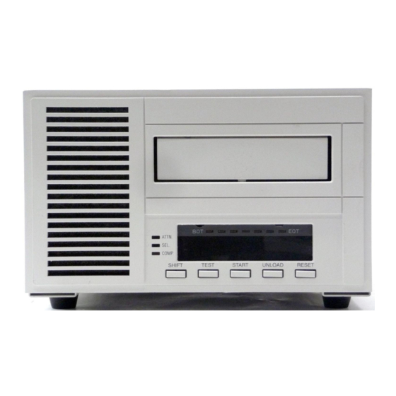
3-4 FLUSH-MOUNTED AUTOMATIC CARTRIDGE LOADER CONTROLS AND INDICA- TORS (OPTIONAL EQUIPMENT) M2488 CONTROLS AND INDICATORS The following paragraphs illustrate and describe front, rear and bottom of the M2488 tape drive. 3-2.1 M2488 Front Panel Controls and Indicators The M2488 front panel is illustrated in Figure 3-1 and described in Table 3-1. -
Page 44: Table 3-1. M2488 Front Panel Controls And Indicators
CONTROLS AND INDICATORS M2488 USER’S GUIDE Table 3-1. M2488 Front Panel Controls and Indicators FIGURE AND CONTROLS AND DESCRIPTION INDEX NO. INDICATORS ATTN LED When a mount/demount message is received from the host system, the ATTN LED blinks to prompt the operator to mount the cartridge. -
Page 45: 3-2.2 M2488 Rear Panel Controls
M2488 USER’S GUIDE CONTROLS AND INDICATORS 3-2.2 M2488 Rear Panel Controls The rear panel is illustrated in Figure 3-2 and described in Table 3-2. Figure 3-2. M2488 Rear Panel Controls Table 3-2. M2488 Rear Panel Controls FIGURE AND CONTROLS AND DESCRIPTION INDEX NO. -
Page 46: 3-2.3 M2488 Bottom Panel Controls
M2488 USER’S GUIDE 3-2.3 M2488 Bottom Panel Controls The bottom panel is illustrated in Figure 3-3 and described in Table 3-3. FRONT PANEL Figure 3-3. M2488 Bottom Panel Controls Table 3-3. M2488 Bottom Panel Controls FIGURE AND CONTROLS AND DESCRIPTION INDEX NO. -
Page 47: Automatic Cartridge Loader Controls And Indicators (Optional Equipment)
M2488 USER’S GUIDE CONTROLS AND INDICATORS AUTOMATIC CARTRIDGE LOADER CONTROLS AND INDICATORS (OPTIONAL EQUIPMENT) Figure 3-4 through Figure 3-6 and Table 3-4 through Table 3-6 illustrate and describe the controls and indicators on the Automatic Cartridge Loader (ACL). 3-3.1 ACL Front Panel Controls and Indicators Figure 3-4 and Table 3-4 illustrate and describe the front panel of the ACL. -
Page 48: 3-3.2 Acl Rear Panel Cables
CONTROLS AND INDICATORS M2488 USER’S GUIDE Table 3-4. ACL Front Panel Controls and Indicators (Continued) FIGURE AND CONTROLS AND DESCRIPTION INDEX NO. INDICATORS Message Display Displays the background, host, fixed, not-ready, check or configuration messages with eight alphanumeric characters, including symbols. -
Page 49: 3-3.3 Acl Top Panel Controls
M2488 USER’S GUIDE CONTROLS AND INDICATORS Table 3-5. ACL Rear Panel Cables FIGURE AND CONTROLS AND DESCRIPTION INDEX NO. INDICATORS Display Cable CNJ41 Control Cable CNJ28 3-3.3 ACL Top Panel Controls Figure 3-6 and Table 3-6 illustrate and describe the top panel of the ACL. -
Page 50: Flush-Mounted Automatic Cartridge Loader Controls And Indicators (Optional Equipment)
CONTROLS AND INDICATORS M2488 USER’S GUIDE FLUSH-MOUNTED AUTOMATIC CARTRIDGE LOADER CONTROLS AND INDICATORS (OPTIONAL EQUIPMENT) The Flush-mounted Automatic Cartridge Loader (FACL) is illustrated and described in the following paragraphs. 3-4.1 FACL Front Panel Controls and Indicators Figure 3-7 and Table 3-7 illustrate and describe the FACL front panel. -
Page 51: Table 3-7. Facl Front Panel Controls And Indicators
M2488 USER’S GUIDE CONTROLS AND INDICATORS Table 3-7. FACL Front Panel Controls and Indicators FIGURE AND CONTROLS AND DESCRIPTION INDEX NO. INDICATORS Message Display Displays the background, host, fixed, not-ready, check or con- figuration messages with eight alphanumeric characters, includ- ing symbols. -
Page 52: 3-4.2 Facl Rear Panel Controls And Cables
CONTROLS AND INDICATORS M2488 USER’S GUIDE 3-4.2 FACL Rear Panel Controls and Cables Figure 3-8 and Table 3-8 illustrate and describe the FACL rear panel. Figure 3-8. FACL Rear Panel Controls and Cables Table 3-8. FACL Rear Panel Controls and Cables... -
Page 53: Configuration
This procedure describes the steps required to access and configure the user settable options. All dis- plays refer to the Operator Panel display on the M2488 tape drive or the medium changer. The menu structure is shown below with the SETTING menu shaded: Table 4-1. -
Page 54: Table 4-2. Settable Options Description
OPTION SETTINGS DESCRIPTION SETTINGS 70: S.TAR TARGID: 0 The SCSI target ID assigned to the M2488 system. 71: S.LUN LUN: 0 The logical unit number assigned to the tape drive. 72: S.LNG ENGLISH Select the language of the fixed display messages. - Page 55 M2488 USER’S GUIDE CONFIGURATION Table 4-2. Settable Options Description (Continued) DEFAULT OPTION SETTINGS DESCRIPTION SETTINGS If NO, the drive’s Target ID is not displayed when no cartridge is 74: S. N: NO loaded. If YES, the drive’s Target ID is displayed when no cartridge is dis- played.
-
Page 56: Table 4-3. S.ft1 Bit Description
CONFIGURATION M2488 USER’S GUIDE Table 4-3. S.FT1 Bit Description VALUE DESCRIPTION Disable internal Retry Buffer retries. Enable internal Retry Buffer retries. Disable all host data phase retry. (Disallows DISCONNECT or RESTORE POINTERS during data phase.) Enable all host data phase retry. -
Page 57: Table 4-4. S.ft2 Bit Description
Support ANSI SCSI-3 Write Buffer modes 6 and 7. Reference the Write Buffer com- mand description in the M2488 for a description of Write Buffer modes 6 and 7. Write Buffer modes 6 and 7 are reserved (per ANSI SCSI-2). - Page 58 ANSI SCSI-3 Density Code 28h (36-track) is supported in the Mode Sense/Select Block Descriptor. For more information, refer to the Density Code 28h information and the Mode Sense/Mode Select commands in the M2488 Product Guide. b) ANSI SCSI-3 REPORT DENSITY SUPPORT command is supported.
-
Page 59: Table 4-7. S.ft5 Bit Description
M2488 USER’S GUIDE CONFIGURATION Table 4-7. S.FT5 Bit Description VALUE DESCRIPTION Reserved The EOM bit is treated in non-ANSI compliant mode. EOM is on in unsolicited REQUEST SENSE data when the MTU is at PBOT or LBOT as well as for the conditions described for a value of 0. -
Page 60: 4-2.1 Setting Target Id
CONFIGURATION M2488 USER’S GUIDE 4-2.1 Setting Target ID ** NOTE ** Remove medium changer magazine (if mounted) prior to performing this procedure. The following procedure describes the steps required to set the Target ID. Step 1. Press and hold both the TEST and UNLOAD keys, wait for OFFLINE to be displayed then release both keys. -
Page 61: Loading New Firmware
CONFIGURATION LOADING NEW FIRMWARE The M2488 tape drive contains a substantial amount of firmware (software) used to control the tape drive hardware. The firmware is stored in non-volatile memory within the tape drive. From time to time new firmware will become available for the M2488 tape drive. This new firmware will be provided either on a code image tape cartridge or as a binary code image file. -
Page 62: 4-3.2 Copying From A Binary Code Image File
CONFIGURATION M2488 USER’S GUIDE Code Load Procedure Using Code Image Tape Cartridge STEP ACTION Power-up tape drive, wait for initialization to complete. TEST UNLOAD OFFLINE Press and hold both the keys, wait for to be displayed then DIAGMODE release both keys. -
Page 63: Drive Information
M2488 USER’S GUIDE CONFIGURATION DRIVE INFORMATION Use the Inquiry menu to display or modify selected information about the M2488 configuration. An explanation of this menu is given in Table 4-9. Table 4-9. Operator Panel Top Level Menus - Information (Inquiry) -
Page 64: Table 4-10. Information Description
CONFIGURATION M2488 USER’S GUIDE Step 2. Press the START push-button until INQUIRY is displayed. The information available is described in Table 4-10. Step 3. Press the TEST pushbutton. The first item, REV LEVL, is displayed. Press TEST to view the vendor information or Step 4. -
Page 65: Mode
Section 4-2 ↓ START Copy new firmware from a code User’s Guide LOADCODE image tape cartridge into non- Section 4-3 volatile memory of M2488. ↓ START View M2488 Information User’s Guide INQUIRY Section 4-4 ↓ START Display or change selected Tape User’s Guide... -
Page 66: Table 4-15. Information Description
If Y, the setting data is written to nonvolatile memory. If N, the setting data is not written to nonvolatile memory. * Refer to the M2488 Product Guide, CG00000-0115xx, Chapter 5 for Mode Page 00 information. 4-14 CG00000-011403 REV. A... -
Page 67: Operating Procedures
INTRODUCTION This chapter provides information on the following subject areas: 5-2 TAPE CARTRIDGE FUNCTIONS 5-3 POWER ON SEQUENCE 5-4 M2488 TAPE DRIVE OPERATION 5-5 MEDIUM CHANGER MAGAZINE PROCEDURES 5-6 MEDIUM CHANGER OPERATING MODES 5-7 OPERATOR PANEL MESSAGES 5-8 MEDIUM CHANGER MESSAGES... -
Page 68: 5-2.3 Tape Cartridge Handling Instructions
8. Remove the cartridge from the drive when temperatures exceed 32° C for more than 12 hours. This will prevent adhesion problems between the tape and head. POWER ON SEQUENCE This procedure provides instructions for power-on of the M2488 tape drive with or without an attached medium changer. STEP ACTION On the rear panel, turn the power switch to the on (I) position. -
Page 69: 5-4.2 Tape Rewind
RESET START 5-4.3 Unload a Tape Cartridge from the M2488 Tape Drive Unloading may be done by either of these methods. 1. The host system sends an UNLOAD command to the drive. Remove the ejected cartridge. . NT RDYU is displayed. Then press 2. -
Page 70: 5-5.2 Unload Tape Cartridges From An Acl Magazine
OPERATING PROCEDURES M2488 USER’S GUIDE 5-5.2 Unload Tape Cartridges from an ACL Magazine The procedure is the same for both the 5 and 10-cartridge magazine STEP ACTION Remove magazine from the ACL. Release cartridge lock. If only one cartridge is to be unloaded, press the cartridge lock bar. If several cartridges are to be unloaded, press the unlock button. -
Page 71: 5-5.4 Unload Tape Cartridges From A Facl Magazine
M2488 USER’S GUIDE OPERATING PROCEDURES 5-5.4 Unload Tape Cartridges from a FACL Magazine STEP ACTION Remove magazine from the FACL. * Release cartridge lock. If only one cartridge is to be unloaded, press the cartridge lock bar. If several cartridges are to be unloaded, press the unlock button. -
Page 72: 5-6.4 Hand Operation Method
OPERATING PROCEDURES M2488 USER’S GUIDE 5-6.4 Hand Operation Method This refers to using the medium-changer without a magazine. A cartridge is placed into the tape drive and the cartridge is then automatically loaded. (The medium-changer mode seen at the SCSI inter- face, System or Auto, is not changed when the hand operation method is used.) -
Page 73: 5-7.5 Check Messages
M2488 USER’S GUIDE OPERATING PROCEDURES 5-7.5 Check Messages This type of message is displayed when a drive error is detected and requires operator intervention. The messages either contain CHK with a hexadecimal error code or indicates that the operator has made an error. -
Page 74: Acl Operating Instructions
OPERATING PROCEDURES M2488 USER’S GUIDE ACL OPERATING INSTRUCTIONS The ACL and the ACL with magazine are shown in Figure 5-4 and Figure 5-5 respectively. Figure 5-4. ACL Figure 5-5. ACL with Magazine 5-9.1 Select the ACL Mode After selecting the mode with this procedure, only use the procedures for that mode. -
Page 75: 5-9.3 Eject The Acl Magazine
M2488 USER’S GUIDE OPERATING PROCEDURES 5-9.3 Eject the ACL Magazine STEP ACTION NT RDYU NT RDYF Press RESET. The MAGAZINE START LED turns off and is dis- played. If a cartridge is loaded, press UNLOAD. The cartridge is returned to the magazine. -
Page 76: Facl Operating Instructions
OPERATING PROCEDURES M2488 USER’S GUIDE 5-10 FACL OPERATING INSTRUCTIONS The FACL is shown in Figure 5-6. Its operation is presented in the following paragraphs. lock tab Figure 5-6. FACL 5-10.1 Open and Close FACL Door To open the spring-loaded door, press PUSH. If the door does not open, press down on the lock tab (side panel) and open the door. -
Page 77: 5-10.4 Eject The Facl Magazine
M2488 USER’S GUIDE OPERATING PROCEDURES 5-10.4 Eject the FACL Magazine Refer to Figure 5-7. STEP ACTION AUTOLOAD OPERATION INTERRUPTED Press RESET, is displayed. Press RESET. Open the door (see paragraph 5-10.1) and press PUSH on the magazine mounting tray. The mount- ing tray moves forward. -
Page 78: 5-10.5 Facl Auto Mode Operation
OPERATING PROCEDURES M2488 USER’S GUIDE 5-10.5 FACL Auto Mode Operation STEP ACTION Press START to load the magazine. The first cartridge is loaded and the tape is positioned at BOT. The drive enters the ready state. When the LOAD UNLOAD command is issued , the tape cartridge is ejected and stored in the mag- azine. -
Page 79: Maintenance And Servicing
If the exterior is dirty, a soft damp cloth with mild detergent may be used for cleaning. 6-2.2 Head Cleaning Procedure This procedure is used to perform normal head cleaning on the M2488 with a cleaning cartridge. STEP ACTION With power applied, insert the cleaning cartridge into the tape drive. -
Page 80: 6-2.3 Air Filter Procedure
MAINTENANCE AND SERVICING M2488 USER’S GUIDE 6-2.3 Air Filter Procedure Inspect the air filter. If dirty, use the remove and replace instructions which follow. 6-2.3.1 Air Filter Removal See Figure 6-1. STEP ACTION Insert a screwdriver into the bottom left of the front panel under the air filter. -
Page 81: Performance Verification
MAINTENANCE AND SERVICING PERFORMANCE VERIFICATION The M2488 performs a selftest upon power on. During the selftest, SELFTEST will be displayed. Upon successful completion of the selftest, the tape drive will return to normal operation with an . If a malfunction occurs, an error code is displayed. Refer to the error code description. -
Page 82: Cartridge Recovery With An Acl
A description of each check code is contained in the M2488 PRODUCT GUIDE, Appendix E. The operator should press the RESET key to eject the cartridge and magazine after recording the check code and associated text. -
Page 83: 6-5.2 Cartridge Recovery With Mount Arm Obstruction
M2488 USER’S GUIDE MAINTENANCE AND SERVICING Complete the steps of the procedure in the order presented. While in the Test Mode, the START and UNLOAD pushbuttons enable the various electromechanical assemblies to move vertically or hori- zontally. STEP ACTION Power off the tape drive. - Page 84 MAINTENANCE AND SERVICING M2488 USER’S GUIDE CG00000-011403 REV. A April 1997...
-
Page 85: Parts List
PARTS LIST CHAPTER 7 PARTS LIST INTRODUCTION Chapter 7 provides parts information on the M2488 Cartridge Tape Drive and optional equipment as described in the following paragraphs: 7-2 M2488 MODELS AND OPTIONS M2488 MODELS AND OPTIONS Table 7-1 describes the M2488 Cartridge Tape Drive models available. The Description column describes all equipment that is included in that model/part number. - Page 86 Flush-mount Automatic Cartridge Loader Cartridge Magazine 7 CA01951-0241 FACL 7-cartridge Magazine M2483A21 Rack Mounting B03B-5530-H021A M2488, with or without ACL, rack-mount tray M2483A22 Front Panel B03B-5530-H022A Front Fitting Panel for tray with 1 drive in right side M2483A23 Front Panel B03B-5530-H023A...
-
Page 87: Glossary
M2488 USER’S GUIDE GLOSSARY APPENDIX G GLOSSARY This glossary defines all acronyms associated with the M2488 tape drive. ACRONYM DEFINITION A RMS Amperes Root-Mean-Square Alternating Current Acknowledge Automatic Cartridge Loader Asynchronous Event Notification AENC Asynchronous Event Notification Capability American National Standard Institute... - Page 88 GLOSSARY M2488 USER’S GUIDE ACRONYM DEFINITION Change Active Format Change Active Partition Command Descriptor Block Compression Engine Check command Command Queuing CmdQ Compress COMP Connector Jack Connector Plug Change Partition or Control Processor Cyclic Redundancy Check Read Data ECC Summary Register (2/7)
- Page 89 M2488 USER’S GUIDE GLOSSARY ACRONYM DEFINITION Device Offline DevOfL Density ID Direct Memory Access Disable Queuing DQUE Dynamic Random Access Memory DRAM Drive Error DRV ERR Disable Save Data Set Ready Drive Tape Controller DTDC Data Transfer Disconnect Control Disable Transfer on Error...
- Page 90 GLOSSARY M2488 USER’S GUIDE ACRONYM DEFINITION Error Recovery Procedure Action ERPA Enable Threshold Comparison Error Track Pointers Group A ETPA ETPB Error Track Pointers Group B EVPD Enable Vital Product Data FACL Flush-mounted Automatic Cartridge Loader Formatter Data Transfer Control...
- Page 91 M2488 USER’S GUIDE GLOSSARY ACRONYM DEFINITION Incorrect Length Indicator Immediate Immed Import/Export ImpExp Interrupt Enable INTEN Interface Personality Module IRCM Interrupt Request Controller mask International Standards Organization kilobyte kilogram pounds lbs. Light Emitting Diode Logical End-of-Tape LEOT Last In, First Out...
- Page 92 GLOSSARY M2488 USER’S GUIDE ACRONYM DEFINITION megabytes per second MB/s medium changer Medium Changer Logical address megahertz millimeter milliseconds Most Significant Byte Message MTBF Mean-Time-Between-Failures Magnetic Tape Controller Mean-Time-To-Repair MTTR Magnetic Tape Unit nanoseconds NVRAM Nonvolatile Random Access Memory Operation Code...
- Page 93 M2488 USER’S GUIDE GLOSSARY ACRONYM DEFINITION Product ID Parameters Savable Power Supply Unit Random Access Memory Read Block Error register RBID Read Block ID Recover Buffer Order read Read Circuit Control Register Read data Error Register Read Logic (Printed Circuit Board)
- Page 94 GLOSSARY M2488 USER’S GUIDE ACRONYM DEFINITION Select Synchronize at Early Warning SFTRE Soft Reset Scatter/Gather logic SCSI Interface Controller Suppress Incorrect Length Indication SILI Sense Key Specific Valid SKSV SNDA Stop On consecutive Filemarks SOCF Save Pages SCSI Protocol Controller...
- Page 95 M2488 USER’S GUIDE GLOSSARY ACRONYM DEFINITION Volts AC Variable Frequency Oscillator Control register Vital Product Data WBus wide bus Write Circuit Control register Wide Data Transfer Request WDTR Write Error Length register Write Error Summary register Write Protected Write Write Residual Byte...
- Page 96 GLOSSARY M2488 USER’S GUIDE G-10 CG00000-011403 REV. A April 1997...
- Page 97 ACL Rear Panel UG 3-6 ACL Top Panel UG 3-7 FACL Front Panel UG 3-8 FACL Rear Panel UG 3-10 M2488 Bottom Panel UG 3-4 M2488 Front Panel UG 3-1 M2488 Rear Panel UG 3-3 DATA COMPATIBILITY UG 1-3 DATA INTEGRITY UG 1-3...
- Page 98 INDEX M2488 USER’S GUIDE ENVIRONMENTAL INFORMATION UG 1-8 Non-Operating UG 1-8 Operating UG 1-8 ERROR RECOVERY UG 6-3 CHK XX UG 6-3 NVRAM Initialization UG 6-3 OZONE UG 6-3 FACL OPERATING INSTRUCTIONS UG 5-10 Eject the FACL Magazine UG 5-11...
- Page 99 PERFORMANCE VERIFICATION UG 6-3 POWER AND UTILITY INFORMATION UG 1-7 POWER ON SEQUENCE UG 5-2 PREPARATION FOR USE UG 2-14 PREPARING THE M2488 AND ITS OPTIONAL EQUIPMENT UG 2-1 PREVENTIVE MAINTENANCE UG 6-1 Air Filter UG 6-2 Equipment Cleaning UG 6-1...
- Page 100 INDEX M2488 USER’S GUIDE SAFETY AND EMI COMPLIANCE UG 1-10 SCSI Connectors UG 2-8 Setting Target ID UG 4-8 STORAGE PROCEDURES UG 1-9 Tape Cartridge UG 5-1 File Protection UG 5-1 Handling UG 5-2 Handling Instructions UG 5-2 Labeling UG 5-1...
- Page 101 COMMENT FORM We would appreciate your comments and suggestions regarding this manual. Manual Code C144-E018-03EN Manual Name M2488 CARTRIDGE TAPE DRIVE USER’S GUIDE Please mark each item: E (Excellent), G (Good), F (Fair), P (Poor) General appearance Illustrations Technical level...
Need help?
Do you have a question about the m2488 and is the answer not in the manual?
Questions and answers