Table of Contents
Advertisement
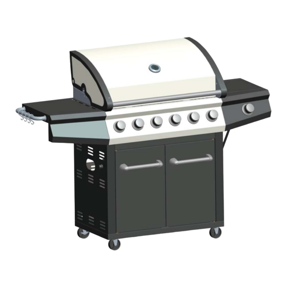
6 + 1 BURNER GAS GRILL
DANGER
If you smell gas:
1. Shut off gas to the appliance.
2. Extinguish any open flame.
3. Open Lid.
4. If odor continues, keep away from the
appliance and immediately call your gas
supplier or your fire department.
Consumer: Retain this manual for future reference.
Installer: Leave this manual with consumer.
Questions, problems, missing / replacement parts? Before returning to your retailer,
call our customer service department at 1-866-814-0585, 8 a.m.-8 p.m., EST,
Monday-Friday.
USER MANUAL
MODEL NO.: SRGG61202
SKU NO.: 259-3066
FOR OUTDOOR USE ONLY
WARNING
1. Do not store or use gasoline or other
flammable liquids or vapors in the
vicinity of this or any other appliance.
2. An LP cylinder not connected for use
shall not be stored in the vicinity of this
or any other appliance.
3194320
Advertisement
Table of Contents

Subscribe to Our Youtube Channel
Related Manuals for Master cook SRGG61202


Summary of Contents for Master cook SRGG61202
- Page 1 6 + 1 BURNER GAS GRILL USER MANUAL MODEL NO.: SRGG61202 SKU NO.: 259-3066 3194320 DANGER WARNING If you smell gas: 1. Do not store or use gasoline or other 1. Shut off gas to the appliance. flammable liquids or vapors in the 2.
-
Page 2: Table Of Contents
TABLE OF CONTENTS SECTION ONE SECTION FOUR Safety Instructions………………………… 3 Operating Instructions………………..… Placement of the Grill……………………...6 Lighting Instructions…………………….. SECTION TWO SECTION FIVE Exploded View…………………………...… Using the Side Burner……………...…… Part List ..…...……………………………… Grilling guide……………...……..... Tools required & Hardware ……………… Care & Maintenance ………………….… Cleaning burners ………………….….. -
Page 3: Safety Instructions
SAFETY INSTRUCTIONS RECOGNIZED SAFETY SYMBOLS, WORDS AND LABELS DO NOT LEAVE THE GRILL UNATTENDED WARNING WHILE COOKING. Do not try lighting this appliance without first reading the “LIGHTING INSTRUCTIONS” section of this manual. WARNING: Always keep your face and body as far away from the burner as possible when lighting. - Page 4 SAFETY INSTRUCTIONS CHILDREN SHOULD NOT BE LEFT ALONE OR TESTED ACCORDANCE WITH Z21.58-2007 / CSA 1.6- 2007 & ANS Z21.58a- UNATTENDED IN AN AREA WHERE THE GRILL IS BEING USED. NEVER ALLOW THEM TO SIT, STAND 1.6b-2012 STANDARD OUTDOOR OR PLAY ON OR AROUND THE GRILL AT ANY TIME. COOKING GAS APPLIANCES.
- Page 5 SAFETY INSTRUCTIONS Keeping outdoor cooking gas appliance area clear and When using the grill, do not touch the grill rack, free from combustible materials, gasoline and other flam- burner grate or immediate surroundings as these mable vapors and liquids. areas become extremely hot and could cause burns.
-
Page 6: Placement Of The Grill
PLACEMENT OF THE GRILL MINIMUM CLEARANCE: LOCATION 2 feet Clearance from both sides of combustible When determining a suitable location take into material, and 3 feet Clearance from the back. account concerns such as exposure to wind, proximity to traffic paths and keeping any gas supply lines as short as possible. -
Page 7: Exploded View
EXPLODED VIEW... -
Page 8: Part List
PART LIST Part # Description Part # Description Hood assembly Left door assembly Warming rack Cabinet back panel Cooking grid Right door assembly Main burner Cabinet right panel assembly Flame tamer Door handle Grease tray Bottom panel Left side shelf assembly Unlocking caster Body assembly Locking caster... -
Page 9: Tools Required & Hardware
TOOLS REQUIRED (Not included) Phillips Head Screwdriver Adjustable Wrench HARDWARE Hardware # Description Picture M6 x 10 bolt D8 washer M4 x 10 bolt M8 nut M5 x 12 bolt M6 x 12 bolt M4X10 cylinder head screw M8 x 45 bolt M6 x 12 thumbscrew... -
Page 10: Assembly Instructions
ASSEMBLY INSTRUCTIONS STEP 1 Turn over the bottom panel (27), install two locking casters (29) and two unlocking casters (28) with sixteen M6 x 10 bolts (AA) onto bottom panel (27); Install weight block (31) on bottom panel (27) with two D8 washers (BB), two M8 nuts (DD) and two M8 x 45 bolts (HH). - Page 11 ASSEMBLY INSTRUCTIONS STEP 3 Install integrated ignition (20) into mounting hole of cabinet left panel assembly (21), then fix the cabinet left panel assembly (21) onto bottom panel (27) with two M6 x 12 bolts (FF). Hardware Used M6 x 12 bolt 2pcs STEP 4 Install cabinet back panel (23) to bottom panel (27) with two M6 x 12 bolts(FF), locking panel assembly...
- Page 12 ASSEMBLY INSTRUCTIONS STEP 5 Note: When installing the handle on the front door, to avoid the bolts accidentally drop inside the door, please make sure to insert the hollow tube (35) into the hole first, put the bolt through the door panel, and then screw tightly to install the handle on the door.
- Page 13 ASSEMBLY INSTRUCTIONS STEP 7 Install grill body assembly (1 & 8) to cabinet assembly with four M6 x 12 bolts (FF). Note: It should be done with 2 people for safety and accuracy. Hardware Used M6 x 12 bolt 4pcs STEP 8 Attach the handle with hook (36) to the left side shelf assembly (7) with two M6 x 12 thumbscrews (II).
- Page 14 ASSEMBLY INSTRUCTIONS STEP 9 Hang right side shelf assembly (12) on four pre-installed M5 x 16 bolts, tighten it. Lock front panel of right side shelf assembly (12) to main control panel with two M5 x 12 bolts (EE). Hardware Used M5 x 12 bolt 2pcs STEP 10...
- Page 15 ASSEMBLY INSTRUCTIONS STEP 11 Unscrew the pre-installed nut from 1/4" side burner gas tube(11). Attach the 1/4" side burner gas tube (11) to side burner inlet. Use 2 wrenches to tighten. One wrench to hold and immobilize the nut at burner inlet, while tightening the gas tube nut (see below). STEP 12 Place grease tray (6) into grill body, tighten it with two M5 x 12 bolts (EE).
- Page 16 ASSEMBLY INSTRUCTIONS STEP 13 Put grease cup (18) into grease cup hanger (17). Hang the grease cup tray assembly(17&18) under grease tray (6). STEP 14 Place six flame tamers (5), two cooking grids (3) and one warming rack (2) into grill body. Place side burner rack (10) into right side burner shelf assembly (12).
- Page 17 ASSEMBLY INSTRUCTIONS STEP 15 Connect six red burner lighter wires with six 2.8 x 0.5 normal terminals. Connect one white switch terminal’s wire to 4.8 x 0.8 switch terminal. Connect one black earthling wire with 4.8 x 0.8 earthing terminal. Note: The earthing wire and igniter switch wire must be inserted into the positions as figure shown.
-
Page 18: Gas Cylinder Installation Instruction
GAS CYLINDER INSTALLATION INSTRUCTIONS STEP 1 Place gas cylinder (not included) into the hole at cylinder bottom panel(27) Screw the cylinder locking bolt (33) to secure the gas cylinder. Gas cylinder (1pc) STEP 2 1 Check to ensure that the valve of gas cylinder is securely turned off prior to making the connection If not, turn the valve clockwise to turn it off. -
Page 19: Gas Hook-Up
GAS HOOK-UP Only the pressure regulator and hose assembly supplied Main Manifold operating pressure: 11” water column (W.C.)/ with the grill should be used. Any replacement pressure regulator and hose assembly must be specified by the P Gas Cylinder must be fitted with Overfill Prevention grill manufacturer. - Page 20 GAS HOOK-UP QCC-1 QUICK CLOSING COUPLING This appliance is designed to be used with an LP gas To disconnect LP gas cylinder: cylinder equipped with the QCC-1 Type 1 Quick Closing 1. Turn the burner valves off. Coupling system which incorporates new safety features required by the American National Standard Institute 2.
-
Page 21: Leak Testing
LEAK TESTING GAS FLOW CHECK GENERAL Each grill burner is tested and adjusted at the factory prior Although all gas connections on the grill are leak to shipment; however, variations in the local gas supply tested at the factory prior to shipment, a complete gas may make it necessary to adjust the burners, the flames tightness check must be performed at the installation of the burners should be visually checked. -
Page 22: Installer Final Check
INSTALLER FINAL CHECK OPERATING INSTRUCTIONS Specified clearance maintained 2 feet from USING THE GRILL sides of combustibles, and 3 feet from the back. Grilling requires high heat for searing and proper All internal packaging removed. browning. Most foods are cooked at the “MAX” heat Knobs turn freely. -
Page 23: Lighting Instructions
LIGHTING INSTRUCTIONS WARNING: IMPORTANT! 2 in. 1 in. 1 inch BEFORE LIGHTING… Inspect the gas supply hose prior to turning the gas 0 in. “ON”. If it is evident there is excessive abrasion or wear, or the hose is cut, it must be replaced prior to Burner flames should be blue and stable with no the grill being put into operation. - Page 24 LIGHTING INSTRUCTIONS Keep a spray bottle of soapy water near the gas supply valve and check the connections before each use. Do not attempt to light the grill if odor of gas is present. Call for customer service.
-
Page 25: Using The Side Burner
USING THE SIDE BURNER WARNING: IMPORTANT! MATCH LIGHTING THE SIDE BURNER 1. Open the lid to the side burner before lighting. 2. Turn the burner control knob to "OFF". USING THE SIDE BURNER 3. Strike and carefully place a match approximately 1/2" Inspect the gas supply hose prior to turning the gas (1 to 2 cm) from the burner. -
Page 26: Grilling Guide
GRILLING GUIDE Outdoor grilling is really quite simple. You'll succeed with DIRECT COOKING burgers, dogs, or steaks usually on your very first try. With experience, you will learn how to work with your Direct cooking involves grilling your meat directly over grill, creating more imaginative meals all the time. -
Page 27: Care & Maintenance
CARE & MAINTENANCE BURNERS CAUTION: Ensure the gas supply is off and the knobs are in the All cleaning and maintenance should be done when grill “OFF” position. Make sure the grill is cool. Clean the is cool and with the gas supply turned off at the propane exterior of the burner with a wire brass brush. -
Page 28: Cleaning Burners
CLEANING BURNERS BURNERS & VENTURI TUBES KEEP VENTURI TUBES CLEAN. INSECT WARNING!! Your grill might still light but... Spiders and insects can nest in the burners of this and any other grill, and cause the gas to flow improperly. Backed up gas might also ignite and cause a fire around the venturi tubes at the control panel or the side burner. -
Page 29: How To Replace Main Burner
Ignition hole (upwards) M5x10 bolt. M5 Nut Step 1 Place the main burner (4) onto grill body and cart assembly (8) and make sure the ignition hole face upward and nozzle insert into the main burner tube. Step 2 Fix one main burner (4) to the grill body and cart assembly (8) with one M5 x 10 bolt and one M5 nut. -
Page 30: Trouble Shooting
TROUBLE SHOOTING BEFORE CALLING FOR SERVICE If the grill does not function properly, use the following checklist before contacting your dealer for service. You may save the cost of a service call. PROBLEM SOLUTION When I light the grill, it does -- Make sure you have turned on the gas. -
Page 31: Limited Warranty
ONE-YEAR LIMITED WARRANTY Shinerich Industrial Ltd. warrants your gas grill to be free from manufacturer’s defects in workmanship or material under normal operating conditions for one (1) year from the original date of purchase. This warranty applies if the item is available to the original purchaser only. This warranty applies only to products sold at retail.
Need help?
Do you have a question about the SRGG61202 and is the answer not in the manual?
Questions and answers
I have a Natural gas Shinerich BBQ model SRGG61202N someone has stolen all the nozzle out of it and I’m looking for new ones to replace them, I have no information on what size they are or wear to get them from, any help would be greatly appreciated.