Woodward 2301A Installation And Operation Manual
Speed control
Hide thumbs
Also See for 2301A:
- Installation and operation manual (52 pages) ,
- Quick start manual (18 pages) ,
- Installation and operation manual (40 pages)
Table of Contents
Advertisement
Advertisement
Table of Contents

Related Manuals for Woodward 2301A


Summary of Contents for Woodward 2301A
- Page 1 Installation and Operation Manual 2301A Speed Control Manual 82020 (Revision C)
- Page 2 Woodward Governor Company reserves the right to update any portion of this publication at any time. Information provided by Woodward Governor Company is believed to be correct and reliable. However, no responsibility is assumed by Woodward Governor Company unless otherwise expressly undertaken.
-
Page 3: Table Of Contents
Manual 82020 2301A Speed Control Contents ..........LECTROSTATIC ISCHARGE WARENESS 1. G ............1 HAPTER ENERAL NFORMATION Description......................1 Applications ......................1 References ......................2 Declaration of Incorporation ...................2 2. I ................3 HAPTER NSTALLATION Introduction......................3 Unpacking.......................3 Selection of Speed Range..................3 Power Requirements ....................4 Location Considerations..................4... - Page 4 PCB from the control cabinet, place it in the antistatic protective bag. CAUTION—ELECTROSTATIC DISCHARGE To prevent damage to electronic components caused by improper handling, read and observe the precautions in Woodward manual 82715, Guide for Handling and Protection of Electronic Controls, Printed Circuit Boards, and Modules. Woodward...
-
Page 5: Chapter 1. General Information
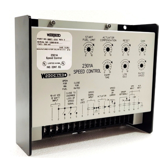
Chapter 1. General Information Description The 2301A Speed Control controls the speed or load of diesel or gas engines, or steam or gas turbines. These power sources are referred to as "prime movers" throughout this manual. The control is housed in a sheet-metal chassis and consists of a single printed circuit board. -
Page 6: References
However, changes must be made to the printed circuit board should a control need to operate the opposite type of actuator. Contact Woodward should it be necessary to change the type of 2301A Speed Control. Changing the supply voltage rating requires exchanging the unit for the properly rated control. -
Page 7: Chapter 2. Installation
2301A Speed Control Chapter 2. Installation Introduction This chapter contains general installation instructions for the 2301A Speed Control. Power requirements, environmental precautions, and location considerations are included to determine the best location for the control. Additional information includes unpacking instructions, electrical connections, and an installation check-out procedure. -
Page 8: Power Requirements
DO NOT power low-voltage versions of the control from high-voltage sources with resistors and zener diodes in series with the control power input. The 2301A control contains a switching power supply which requires a current surge to start properly. -
Page 9: Shielded Wiring
The other end of the shields must be left open and insulated from any other conductor. Do not run shielded signal wires with other wires carrying large currents. See Woodward application note 50532, EMI Control for Electronic Governing Systems, for more information. -
Page 10: External Adjustments
537 or equivalent) to provide about ±5% speed adjustment. Terminals 11 and 12 must be jumpered if the speed trim potentiometer or digital reference unit is not used. The 2301A Speed Control will have a jumper installed in the factory and this must be removed if a speed-trim device is used. - Page 11 Some 2301As may be used to operate prime movers in tandem by wiring the two actuators in series as shown in detail A of the wiring diagram. Tandem operation with a single 2301A control requires that the two engines provide identical power response to identical current signals to each of the actuators.
-
Page 12: Installation Check-Out Procedure
Terminals 17 (–) and 15 (+) are used for auxiliary input from a load sensor. Use of the load sensor and parallel lines allow the 2301A Speed Control to be used in isochronous load-sharing circuits. If the load sensor is not used, droop must be used to share load. -
Page 13: Figure 2-3. Outline Drawing Of 2301A Speed Control
Manual 82020 2301A Speed Control Figure 2-3. Outline Drawing of 2301A Speed Control Woodward... -
Page 14: Figure 2-4. Low Voltage Plant Wiring Diagram
2301A Speed Control Manual 82020 Figure 2-4. Low Voltage Plant Wiring Diagram Figure 2-5. High Voltage Plant Wiring Diagram Woodward... -
Page 15: Chapter 3. Operation And Adjustment
Manual 82020 2301A Speed Control Chapter 3. Operation and Adjustment Initial Pre-Start Settings WARNING—OVERSPEED Overspeed with resultant equipment damage, personal injury, or death is possible when setting up a control system. Read this entire procedure before starting the prime mover for the first time. - Page 16 2301A Speed Control Manual 82020 Close the Close for Rated contact. If the external droop feature is being used it should already be set at isochronous, fully ccw (be careful not to overtorque the pot). NOTE This is for initial prime mover start-up only. For normal start-up, the Close for Rated contact should be open if the prime mover is to start at idle.
-
Page 17: Adjust For Stable Operation
Manual 82020 2301A Speed Control Adjust for Stable Operation If prime-mover operation is stable, go to the "Speed Setting Adjustment" procedure. If the prime mover is hunting at a rapid rate, slowly decrease the gain (turn the potentiometer counterclockwise) until performance is stable. Adjusting the gain may cause a momentary speed change which can be minimized by turning the gain potentiometer slowly. -
Page 18: Actuator Compensation Adjustment
2301A Speed Control Manual 82020 Figure 3-1 illustrates prime mover starts with the RAMP TIME potentiometer fully counterclockwise (no ramp—be careful not to overtorque the pot), step loadings at four different RESET potentiometer settings, and stable, steady-state running conditions. These are typical performance curves on a naturally aspirated (non-turbocharged) diesel engine. -
Page 19: Figure 3-1. Diesel Engine Performance Curve
Manual 82020 2301A Speed Control Figure 3-1. Diesel Engine Performance Curve Woodward... -
Page 20: Start Fuel Limit Adjustment
2301A Speed Control Manual 82020 Start Fuel Limit Adjustment NOTE Start-fuel limit is not recommended for use with reverse-acting controls. With loss of speed signal, the reverse acting control will position the actuator at the start-fuel level if the failed-speed-signal override is activated. -
Page 21: Figure 3-2. Droop Adjustment
Manual 82020 2301A Speed Control Too little droop will cause instability, similar to that experienced with improperly adjusted GAIN and RESET. Units running against an isolated bus often need droop set to a particular level, to prevent excessive off speed when load changes. Droop is usually expressed as... -
Page 22: Figure 3-3. Droop Base Load With 5% Droop
2301A Speed Control Manual 82020 Figure 3-3. Droop Base Load with 5% Droop Synchronize the generator with the bus and close the tie-breaker. Return the RATED SPEED potentiometer to the mark made in step 2. Load the generator by turning the droop potentiometer counterclockwise until full load is achieved. -
Page 23: Chapter 4. Description Of Operation
Description of Operation Introduction The 2301A Speed Control monitors prime-mover speed and maintains it at the correct operating level. With the addition of a load sensor the system will share the load with other generators when two or more systems are running in parallel. -
Page 24: Auxiliary Inputs
2301A Speed Control Manual 82020 The speed-signal voltage is compared to the reference voltage at the summing point. If the speed-signal voltage is lower or higher than the reference voltage, a signal is sent by the control amplifier calling for an increase or decrease in speed. - Page 25 Reverse Acting Controls The reverse-acting 2301A Speed Control and its actuator are designed so that zero voltage to the actuator corresponds to maximum fuel to the prime mover. The actuator usually used with a reverse-acting control has a mechanical governing mechanism included (see Figure 4-3).
-
Page 26: Figure 4-3. Reverse Acting System
2301A Speed Control Manual 82020 Figure 4-3. Reverse Acting System Woodward... -
Page 27: Chapter 5. Troubleshooting
Both high-voltage and low- voltage models of 2301A speed controls are available. The low- voltage model will be damaged if connected to a high-voltage supply. The high-voltage model will not operate with a low-voltage supply. - Page 28 If the control does not cut back the actuator voltage when the speed setting is completely ccw the 2301A control may be faulty, or may have the wrong speed range. If the voltage is cut back, (increased on reverse acting controls) look for a problem in the linkage or actuator.
- Page 29 (diesel) or low-idle set screw (gas engine), or the LOW IDLE SPEED setting should be raised. If this does not correct the problem, the 2301A control may be faulty. LOW IDLE SPEED potentiometer. If adjustment of the LOW IDLE SPEED potentiometer causes erratic behavior, replace the control.
- Page 30 2301A Speed Control Manual 82020 Symptom Cause Remedy Prime Mover will not Prime mover not receiving fuel as Check actuator linkage to fuel-controlling stabilize. called for by the actuator. mechanism for lost motion, binding, or excessive loading. Check for a steady fuel pressure of proper value.
-
Page 31: Chapter 6. Service Options
Product Service Options The following factory options are available for servicing Woodward equipment, based on the standard Woodward Product and Service Warranty (5-01-1205) that is in effect at the time the product is purchased from Woodward or the service is performed: •... -
Page 32: Returning Equipment For Repair
Returning Equipment for Repair If a control (or any part of an electronic control) is to be returned to Woodward for repair, please contact Woodward in advance to obtain a Return Authorization Number. When shipping the item(s), attach a tag with the following information: •... -
Page 33: Replacement Parts
To expedite the repair process, contact Woodward in advance to obtain a Return Authorization Number, and arrange for issue of a purchase order for the item(s) to be repaired. No work can be started until a purchase order is received. -
Page 34: Engineering Services
2301A Speed Control Manual 82020 Engineering Services Woodward Industrial Controls Engineering Services offers the following after- sales support for Woodward products. For these services, you can contact us by telephone, by email, or through the Woodward website. • Technical Support •... -
Page 35: Technical Assistance
Type of Fuel (gas, gaseous, steam, etc) Rating Application Control/Governor Information Please list all Woodward governors, actuators, and electronic controls in your system: Woodward Part Number and Revision Letter Control Description or Governor Type Serial Number Woodward Part Number and Revision Letter... - Page 36 Phone +1 (970) 482-5811 • Fax +1 (970) 498-3058 Email and Website—www.woodward.com Woodward has company-owned plants, subsidiaries, and branches, as well as authorized distributors and other authorized service and sales facilities throughout the world. Complete address / phone / fax / email information for all locations is available on our website.
Need help?
Do you have a question about the 2301A and is the answer not in the manual?
Questions and answers