Woodward 2301A Installation And Operation Manual
Speed control with ma speed setting input
Hide thumbs
Also See for 2301A:
- Installation and operation manual (52 pages) ,
- Quick start manual (18 pages) ,
- Installation and operation manual (48 pages)

Subscribe to Our Youtube Channel
Related Manuals for Woodward 2301A


Summary of Contents for Woodward 2301A
- Page 1 Installation and Operation Manual 2301A Speed Control with mA Speed Setting Input Manual 02302 (Revision B)
- Page 2 Woodward Governor Company reserves the right to update any portion of this publication at any time. Information provided by Woodward Governor Company is believed to be correct and reliable. However, no responsibility is assumed by Woodward Governor Company unless otherwise expressly undertaken.
-
Page 3: Table Of Contents
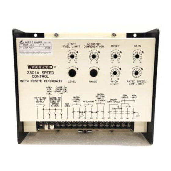
Manual 02302 2301A Speed Control with mA Speed Setting Input Contents ..........LECTROSTATIC ISCHARGE WARENESS 1. G ............1 HAPTER ENERAL NFORMATION Description......................1 Applications ......................2 References ......................3 2. I ................4 HAPTER NSTALLATION Introduction......................4 Unpacking.......................4 Selection of Speed Range..................4 Power Requirements ....................5 Location Considerations..................5... - Page 4 Figure 1-1. 2301A Speed Control................1 Figure 2-1. Speed Range Switch ................4 Figure 2-2. Preparation of Shielded Cables ............6 Figure 2-3. Outline Drawing of Full Authority 2301A Speed Control....10 Figure 2-4. Plant Wiring Diagram .................11 Figure 3-1. Speed Setting Setpoints ..............13 Figure 3-2.
-
Page 5: Electrostatic Discharge Awareness
PCB from the control cabinet, place it in the antistatic protective bag. CAUTION—ELECTROSTATIC DISCHARGE To prevent damage to electronic components caused by improper handling, read and observe the precautions in Woodward manual 82715, Guide for Handling and Protection of Electronic Controls, Printed Circuit Boards, and Modules. Woodward... - Page 6 2301A Speed Control with mA Speed Setting Input Manual 02302 Woodward...
-
Page 7: Chapter 1. General Information
General Information Description The 2301A Full Authority Speed Control controls the speed or load of diesel or gas engines, or steam or gas turbines according to the demand of a process or a computer control signal of 4–20 mA or 1–5 Vdc. -
Page 8: Applications
4–20 mA or a 1–5 Vdc signal indicating the demand of the process, or with a computer circuit which indicates the amount of power or speed needed according to the program logic. The unit offers the features of a 2301A speed control operating with a signal converter. Combining the features of a signal converter with the speed control improves the efficiency and convenience of the control system. -
Page 9: References
However, changes must be made to the printed circuit board should a control need to operate the opposite type of actuator. Contact Woodward should it be necessary to change the type of control. Changing the supply voltage rating requires exchanging the unit for the properly rated control. -
Page 10: Chapter 2. Installation
Chapter 2. Installation Introduction This chapter contains general installation instructions for the 2301A Full Authority Speed Control. Power requirements, environmental precautions, and location considerations are included to determine the best location for the control. Additional information includes unpacking instructions, electrical connections, and an installation check-out procedure. -
Page 11: Power Requirements
Manual 02302 2301A Speed Control with mA Speed Setting Input Power Requirements High and low voltage models of 2301A Full Authority Speed Controls are available. Low voltage models require a supply of 10 to 40 Vdc, 12 W. High Voltage models require a supply of 88 to 120 Vac or 90 to 150 Vdc., 12 W. -
Page 12: External Adjustments
2301A Speed Control with mA Speed Setting Input Manual 02302 Where shielded cable is required, cut the cable to the desired length and prepare the cable as instructed below and shown in Figure 2-2. 1. Strip outer insulation from both ends, exposing the braided or spiral wrapped shield. -
Page 13: Switch Options
Failed Speed Signal Override Circuits in the 2301A Speed Control constantly monitor the signal from the MPU. Should this signal be below a minimum threshold the control sends a minimum fuel signal to the actuator. - Page 14 Terminals 17 (–) and 15 (+) are used for auxiliary input from a load sensor. Use of the load sensor and parallel lines allow the 2301A Speed Control to be used in isochronous load-sharing circuits. If the load sensor is not used, droop must be used to share load.
-
Page 15: Installation Checkout Procedure
Manual 02302 2301A Speed Control with mA Speed Setting Input Installation Checkout Procedure When the installation is completed perform the following check-out procedure before beginning the start-up adjustments in Chapter 3. Visual Inspection: Check the linkage between the actuator and the prime mover for looseness or binding. -
Page 16: Figure 2-3. Outline Drawing Of Full Authority 2301A Speed Control
2301A Speed Control with mA Speed Setting Input Manual 02302 LOW VOLTAGE MODEL HIGH VOLTAGE MODEL Figure 2-3. Outline Drawing of Full Authority 2301A Speed Control Woodward... -
Page 17: Figure 2-4. Plant Wiring Diagram
Manual 02302 2301A Speed Control with mA Speed Setting Input Figure 2-4. Plant Wiring Diagram Woodward... -
Page 18: Chapter 3. Operation And Adjustment
2301A Speed Control with mA Speed Setting Input Manual 02302 Chapter 3. Operation and Adjustment Introduction This chapter contains information on control calibration. It includes initial pre-start up and start up settings and adjustments. WARNING—OVERSPEED Overspeed with resultant equipment damage, personal injury, or death is possible when setting up a control system. -
Page 19: Tailoring The Speed Setting Input
Tailoring the Speed Setting Input The 2301A control can extend the range of the control signal by a 3:1 ratio. (A signal of 8 to 15 mA [2 to 4 V] can be expanded to cover the full 4–20 mA [1–5 volt] range.) This expansion of range allows full speed control over a more limited... -
Page 20: Start-Up Adjustments
2301A Speed Control with mA Speed Setting Input Manual 02302 6. Adjust the Level pot until the signal at terminals 9 and 10 just starts to drop. 7. Increase the control signal to the maximum signal that can be expected (no more than 20 mA or 5 Vdc). -
Page 21: Adjust For Stable Operation
2000 to 6000 Hz speed range (2000 Hz x .05 = 100 Hz). 10. When the above test is completed, close the "Open for Minimum Fuel" contacts. This will put the 2301A in the "run" mode. The "Override Failed Speed Signal" and "Override Start Fuel Limit" contacts should be open during normal operation. -
Page 22: Actuator Compensation Adjustment
2301A Speed Control with mA Speed Setting Input Manual 02302 Increasing the setting of the GAIN potentiometer provides faster transient response (decreases the magnitude of the speed change from a sudden change in load). To achieve optimum response, slowly increase the GAIN (turn the potentiometer clockwise) until the actuator becomes slightly unstable, then slowly turn the GAIN back counterclockwise as necessary to stabilize the actuator. -
Page 23: Figure 3-2. Diesel Engine Performance Curve
Manual 02302 2301A Speed Control with mA Speed Setting Input Figure 3-2. Diesel Engine Performance Curve Woodward... -
Page 24: Start Fuel Limit Adjustment
2301A Speed Control with mA Speed Setting Input Manual 02302 Start Fuel Limit Adjustment NOTE Start-fuel limit is not recommended for use with reverse-acting controls. With loss of speed signal, the reverse acting control will position the actuator at the start-fuel level if the failed-speed-signal override is activated. -
Page 25: Figure 3-3. Droop Adjustment
Manual 02302 2301A Speed Control with mA Speed Setting Input Too little droop will cause instability, similar to that experienced with improperly adjusted GAIN and RESET. Units running against an isolated bus often need droop set to a particular level, to prevent excessive off speed when load changes. -
Page 26: Figure 3-4. Droop Base Load With 5% Droop
2301A Speed Control with mA Speed Setting Input Manual 02302 Figure 3-4. Droop Base Load with 5% Droop 4. Synchronize the generator with the bus and close the tie-breaker. 5. Return the SPEED SETTING INPUT to the input recorded in step 2. -
Page 27: Chapter 4. Description Of Operation
Description of Operation Introduction The 2301A Speed Control monitors prime-mover speed and maintains it at the operating level determined by the speed setting input or by the low or high limit setting. With the addition of a load sensor the system will share the load with other generators when two or more systems are running in parallel. -
Page 28: Auxiliary Inputs
2301A Speed Control with mA Speed Setting Input Manual 02302 The speed-signal voltage is compared to the reference voltage at the summing point. If the speed-signal voltage is lower or higher than the reference voltage, a signal is sent by the control amplifier calling for an increase or decrease in speed. -
Page 29: Actuator Circuit Protection
Manual 02302 2301A Speed Control with mA Speed Setting Input • The START FUEL LIMIT potentiometer provides a means of limiting the fuel-rack position when starting diesel engines. Adjustment of the potentiometer sets the maximum actuator position from no speed until the speed reaches the current speed-reference setting. -
Page 30: Reverse Acting Controls
The actuator usually used with a reverse-acting control has a mechanical governing mechanism included. The speed setting of this mechanical governor is slightly higher than the speed setting of the 2301A. Should the electronics fail, the actuator will try to go to maximum fuel but will be stopped... -
Page 31: Chapter 5. Troubleshooting
The wrong voltage can damage the control. When replacing a control, check the power supply, battery, etc., for the correct voltage as indicated on the name tag on the control. Both high-voltage and low-voltage models of 2301A speed controls are available. The low-voltage model will be damaged if connected to a high-voltage supply. - Page 32 2301A Speed Control with mA Speed Setting Input Manual 02302 Symptom Cause Remedy Prime mover will not start. No actuator voltage at terminals 9 Stop cranking. Check for shorted or Actuator not moving to start- and 10 while cranking. grounded actuator leads by removing fuel position.
- Page 33 Manual 02302 2301A Speed Control with mA Speed Setting Input Symptom Cause Remedy Prime mover overspeeds RATED SPEED/LOW LIMIT setting Set RATED SPEED\LOW LIMIT as only on starts. too high. described in Chapter 3. Amplifier adjustment. 2301A may be adjusted for sluggish operation, causing overspeed on start.
- Page 34 2301A Speed Control with mA Speed Setting Input Manual 02302 Symptom Cause Remedy Low speed is not regulated NOTE: On carbureted prime movers, The Low Limit setting may be below the by LOW LIMIT the minimum fuel stop rpm setting min-fuel position of the actuator or prime- potentiometer.
-
Page 35: Chapter 6. Service Options
Product Service Options The following factory options are available for servicing Woodward equipment, based on the standard Woodward Product and Service Warranty (5-01-1205) that is in effect at the time the product is purchased from Woodward or the service is performed: •... -
Page 36: Returning Equipment For Repair
Returning Equipment for Repair If a control (or any part of an electronic control) is to be returned to Woodward for repair, please contact Woodward in advance to obtain a Return Authorization Number. When shipping the item(s), attach a tag with the following information: •... -
Page 37: Replacement Parts
To expedite the repair process, contact Woodward in advance to obtain a Return Authorization Number, and arrange for issue of a purchase order for the item(s) to be repaired. No work can be started until a purchase order is received. -
Page 38: Engineering Services
2301A Speed Control with mA Speed Setting Input Manual 02302 Engineering Services Woodward Industrial Controls Engineering Services offers the following after- sales support for Woodward products. For these services, you can contact us by telephone, by email, or through the Woodward website. • Technical Support •... -
Page 39: Technical Assistance
Type of Fuel (gas, gaseous, steam, etc) Rating Application Control/Governor Information Please list all Woodward governors, actuators, and electronic controls in your system: Woodward Part Number and Revision Letter Control Description or Governor Type Serial Number Woodward Part Number and Revision Letter... - Page 40 Phone +1 (970) 482-5811 • Fax +1 (970) 498-3058 Email and Website—www.woodward.com Woodward has company-owned plants, subsidiaries, and branches, as well as authorized distributors and other authorized service and sales facilities throughout the world. Complete address / phone / fax / email information for all locations is available on our website.
Need help?
Do you have a question about the 2301A and is the answer not in the manual?
Questions and answers