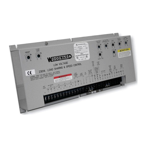
Woodward 2301A Quick Start Manual
Systems for split shaft gas turbines and engine/torque converter applications
Hide thumbs
Also See for 2301A:
- Installation and operation manual (52 pages) ,
- Installation and operation manual (47 pages) ,
- Installation and operation manual (36 pages)
Subscribe to Our Youtube Channel
Summary of Contents for Woodward 2301A
- Page 1 2301A Systems for Split Shaft Gas Turbines and Engine/Torque Converter Applications Application Note 50536...
- Page 2 Woodward Governor Company reserves the right to update any portion of this publication at any time. Information provided by Woodward Governor Company is believed to be correct and reliable. However, no responsibility is assumed by Woodward Governor Company unless otherwise expressly undertaken.
-
Page 3: Table Of Contents
Application Note 50536 2301A Split Shaft Applications Contents ..........LECTROSTATIC ISCHARGE WARENESS 1. G ............1 HAPTER ENERAL NFORMATION Introduction......................1 Selection of Controls ....................2 Power Generation....................2 Reference Publications ..................2 2. I ................4 HAPTER NSTALLATION Introduction......................4 Unpacking.......................4 Selection of Speed Range..................4 Location Considerations..................5... -
Page 4: Electrostatic Discharge Awareness
PCB from the control cabinet, place it in the antistatic protective bag. CAUTION—ELECTROSTATIC DISCHARGE To prevent damage to electronic components caused by improper handling, read and observe the precautions in Woodward manual 82715, Guide for Handling and Protection of Electronic Controls, Printed Circuit Boards, and Modules. Woodward... -
Page 5: Chapter 1. General Information
Chapter 1. General Information Introduction Special 2301A controls are used to provide load sharing and speed control for installations with engines driving loads isolated through torque converters or for split shaft gas turbines. These systems use magnetic pickups (MPUs) on both the engine or gas compressor side of the unit and the power turbine or driven load (tailshaft) side. -
Page 6: Selection Of Controls
The N1 gas turbine or compressor side of the unit is then controlled with the 2301A speed control. A 9905-181 speed control is used for the N1 gas turbine and a 9905-182 is used for the N2 power turbine. -
Page 7: Figure 1-1. Block Diagram Of Speed Control Application
Application Note 50536 2301A Split Shaft Applications Figure 1-1. Block Diagram of Speed Control Application Figure 1-2. Block Diagram of Load Sharing and Speed Control Application Woodward... -
Page 8: Chapter 2. Installation
Chapter 2. Installation Introduction This chapter contains general installation instructions for 2301A split shaft or tailshaft controls. Power requirements, environmental precautions, and location considerations are included to determine the best location for the controls. Additional information includes unpacking instructions, electrical connections, and an installation check-out procedure. -
Page 9: Location Considerations
1. Strip outer insulation from both ends, exposing the braided or spiral wrapped shield. Do not cut the shield on the control end. Cut off the shield on the end away from the 2301A control. 2. Use a sharp, pointed tool to carefully spread the strands of the shield. -
Page 10: Installation Of Controls
Application Note 50536 Installations with severe electromagnetic interference (EMI) may require shielded wire run in conduit, double shielded wire, or other precautions. Contact Woodward or your authorized Distributor for additional information. Figure 2-2. Preparation of Shielded Cables Installation of Controls The two controls used for split shaft or tailshaft governing are normally installed on the same control panel. -
Page 11: External Adjustments
1657-537 or equivalent) to provide about ±5% speed adjustment. Terminals 11 and 12 must be jumpered if the speed trim potentiometer or digital reference unit is not used. The 2301A Speed Control has a jumper installed at the factory which must be removed if a speed-trim device is used. -
Page 12: Idle/Rated Ramp Contact
2301A Split Shaft Applications Application Note 50536 Before start-up of the prime mover, the speed signal is non-existent, activating the failed-speed-signal circuit. On units with cranking motors, the cranking speed is usually sufficient to provide a speed signal, so an override contact is not needed for starting. -
Page 13: Speed Sensor
8 and 7 of the particular governor. No polarity is observed. Use shielded wire and connect the shield only at the 2301A control. The shield must have continuity the entire distance to the MPU. Insulate the shield from all other conductors and from the MPU. -
Page 14: Dynamic Adjustment
2301A Split Shaft Applications Application Note 50536 Visual Inspection: Check the linkage between the actuator and the prime mover for looseness or binding. Refer to the appropriate actuator manual, and Manual 25070, Electronic Control Installation Guide, for additional information on linkage. -
Page 15: Figure 2-3. Plant Wiring Diagram, Split Shaft Speed Control
Application Note 50536 2301A Split Shaft Applications Figure 2-3. Plant Wiring Diagram, Split Shaft Speed Control Woodward... - Page 16 2301A Split Shaft Applications Application Note 50536 Figure 2-4. Plant Wiring Diagram, Split Shaft Load Sharing and Speed Control Woodward...
- Page 18 Phone +1 (970) 482-5811 • Fax +1 (970) 498-3058 Email and Website—www.woodward.com Woodward has company-owned plants, subsidiaries, and branches, as well as authorized distributors and other authorized service and sales facilities throughout the world. Complete address / phone / fax / email information for all locations is available on our website.


Need help?
Do you have a question about the 2301A and is the answer not in the manual?
Questions and answers