Sign In
Upload
Manuals
Brands
Woodward Manuals
Controller
2301A
Woodward 2301A Electronic Load Sharing Manuals
Manuals and User Guides for Woodward 2301A Electronic Load Sharing. We have
6
Woodward 2301A Electronic Load Sharing manuals available for free PDF download: Installation And Operation Manual, Quick Start Manual
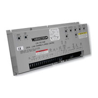
Woodward 2301A Installation And Operation Manual (52 pages)
Electronic Load Sharing and Speed Control 9905/9907 Series UL Listed E97763
Brand:
Woodward
| Category:
Control Unit
| Size: 0.9 MB
Table of Contents
Table of Contents
3
Electrostatic Discharge Awareness
5
Chapter 1. General Information
7
Description
7
Applications
7
References
8
2301A Load Sharing and Speed Control Models, 9905/9907 Series
9
Figure 1-1. 2301A Control Outline Drawing
10
Figure 1-2A. Plant Wiring Diagram (Low-Voltage Supply)
11
Figure 1-2B. Plant Wiring Diagram (High-Voltage Supply)
12
Chapter 2. Installation
13
Unpacking
13
Power Requirements
13
Location Considerations
13
Electrical Connections
13
Shielded Wiring
14
Setting Speed Range
14
Figure 2-1. Preparation and Installation of Shielded Cables
14
Potential Transformer Connections
15
Current Transformer Connections
15
Figure 2-2. Switch S1
15
Droop Contact (Isoch-Droop) and Load Sharing Lines
16
Figure 2-3. Droop Contact and Circuit Breaker Auxiliary Contact
16
Power Supply
17
Minimum Fuel Contact
17
Failed Speed Signal Override
17
Idle/Rated Ramp Contact
18
Actuator Output
18
External Speed Trim
18
Speed and Phase Matching (SPM) Synchronizer
18
Speed Sensor
18
Installation Check-Out Procedure
19
Chapter 3. Operation and Adjustment
20
Initial Pre-Start Settings
20
Start-Up Adjustments
20
Adjust for Stable Operation
22
Speed Setting Adjustment
22
Dynamic Adjustment
22
Actuator Compensation Adjustment
23
Low Idle Speed Adjustment
23
Ramp Time Adjustment
23
Figure 3-1. Diesel Engine Performance Curves
24
Start Fuel Limit Adjustment
25
Speed Sensor Check
25
Current Transformer (CT) Phasing Check
25
Phase Correction Procedure
26
Figure 3-2. Temporary Wiring for Transformer Phase Correction
27
Load Gain Adjustment
29
Droop Adjustment
30
Figure 3-3. Droop Adjustment
30
Figure 3-4. 3% Droop at 60 Hz
31
Chapter 4. Description of Operation
32
Introduction
32
Speed Control
32
Figure 4-1. Speed Control System
32
Figure 4-2. Speed Control Adjustments
33
Terminals for External Devices
34
Paralleling
34
Figure 4-3. Terminal Connections
35
Figure 4-4. Paralleling System
36
Figure 4-5. Paralleling Adjustments
36
Chapter 5. Troubleshooting
37
Troubleshooting Procedure
37
Chapter 6. Service Options
44
Product Service Options
44
Returning Equipment for Repair
45
Replacement Parts
46
How to Contact Woodward
46
Engineering Services
47
Technical Assistance
48
2301A Load Sharing and Speed Control
50
Declarations
51
Advertisement
Woodward 2301A Installation And Operation Manual (47 pages)
Load Sharing & Speed Control with Dual Dynamics
Brand:
Woodward
| Category:
Control Unit
| Size: 1.26 MB
Table of Contents
Table of Contents
3
Warnings and Notices
5
Battery Charging
6
Electrostatic Discharge Awareness
6
Chapter 1. General Information
7
Description
7
Dual Dynamics
7
System Accommodating Features
8
References
9
Chapter 2. Installation
10
Unpacking
10
Selection of Speed Range
10
Power Requirements
10
Figure 2-1. Speed Range Switch
10
Location Considerations
11
Electrical Connections
11
Shielded Wiring
11
Power Sensing and Load Sharing Connections
12
Figure 2-2. Preparation of Shielded Cables
12
Power Supply
13
External Adjustments
14
Switch Options
14
Speed Sensor
15
Dual Dynamic Contact
15
Start Fuel Limit Disable Contact
16
Installation Checkout Procedure
16
Figure 2-3. Plant Wiring Diagram
17
Figure 2-4. Plant Wiring Diagram and Optional Connections
18
Figure 2-5. Outline Drawing of 2301A Speed Control with Dual Dynamics
19
Chapter 3. Operation and Adjustment
20
Initial Pre-Start Settings
20
Start-Up Adjustments
21
Adjust for Stable Operation
22
Speed Setting Adjustment
22
Dynamic Adjustment
22
Actuator Compensation Adjustment
23
Low Idle Speed Adjustment
23
Accel Ramp Time Adjustment
24
Decel Ramp Time Adjustment
24
Start Fuel Limit Adjustment
24
Figure 3-1. Diesel Engine Performance Curves
25
Speed Sensor Check
26
Current Transformer (CT) Phasing Check
26
Phase Correction Procedure
27
Figure 3-2. Temporary Wiring for Transformer Phase Correction
28
Load Gain Adjustment
30
Droop Adjustment
30
Setting Droop and Load Gain, Using an Infinite Bus for Load
31
Figure 3-3. Droop Adjustment
31
Figure 3-4. Droop Base Load with 5% Droop
32
Chapter 4. Description of Operation
33
Introduction
33
Dual Dynamics
33
Figure 4-1. Second Dynamics Adjustments
33
Speed Control
34
Figure 4-2. Speed Control System
34
Figure 4-3. Speed Control Adjustments
35
Terminals for External Devices
36
Paralleling
37
Figure 4-4. Reverse Acting System
37
Figure 4-5. Paralleling System
37
Figure 4-6. Terminal Connections
38
Power Supply
39
Figure 4-7. Paralleling Adjustments
39
Chapter 5. Troubleshooting
40
Chapter 6. Product Support and Service Options
43
Product Support Options
43
Product Service Options
43
Returning Equipment for Repair
44
Replacement Parts
44
Engineering Services
45
Contacting Woodward's Support Organization
45
Technical Assistance
46
Woodward 2301A Installation And Operation Manual (48 pages)
Load Sharing and Speed Control
Brand:
Woodward
| Category:
Controller
| Size: 1.83 MB
Table of Contents
Table of Contents
3
Chapter 1. General Information
5
Description
5
Applications
6
Figure 1-1. 2301A Load Sharing and Speed Control
7
Figure 1-2. Plant Wiring Diagram (9900-430)
8
Figure 1-3. Plant Wiring Diagram (9900-431)
9
Figure 1-4. Plant Wiring Diagram (9900-432)
10
Figure 1-5. Plant Wiring Diagram (9900-433)
11
Chapter 2. Installation
12
Unpacking
12
Power Requirements
12
Location Considerations
12
Electrical Connections
12
Setting Speed Range
13
Potential Transformer Connections
13
Current Transformer Connections
14
Droop Contact (Isoch/Droop) and Load Sharing Lines
14
Power Supply
14
Minimum Fuel Contact
15
Failed Speed Signal Override
15
Idle/Rated Ramp Contact
15
Actuator Output
15
External Speed Trim
16
Speed and Phase Matching (SPM) Synchronizer
16
Speed Sensor
16
Installation Checkout Procedure
16
Chapter 3. Operation and Adjustment
18
Initial Pre-Start Settings
18
Start-Up Adjustments
18
Adjust for Stable Operation
19
Figure 3-1. Diesel Engine Performance Curves
21
Speed Sensor Check
23
Current Transformer (CT) Phasing Check
23
Figure 3-2. Temporary Wiring for Transformer Phase Correction
25
Load Gain Adjustment
27
Droop Adjustment
27
Figure 3-3. Droop Adjustment
28
Chapter 4. Description of Operation
30
General
30
Figure 4-1. Speed Control System
30
Terminals for External Devices
31
Paralleling
32
Figure 4-2. Terminal Connections
32
Figure 4-3. Paralleling System
33
Chapter 5. Troubleshooting
34
Troubleshooting Procedure
34
Chapter 6. Service Options
40
Product Service Options
40
Returning Equipment for Repair
41
Replacement Parts
42
How to Contact Woodward
42
Engineering Services
43
Technical Assistance
44
2301A Control Specifications
47
Advertisement
Woodward 2301A Installation And Operation Manual (40 pages)
Speed Control with mA Speed Setting Input
Brand:
Woodward
| Category:
Controller
| Size: 0.43 MB
Table of Contents
Table of Contents
3
Electrostatic Discharge Awareness
5
Chapter 1. General Information
7
Description
7
Figure 1-1. 2301A Speed Control
7
Applications
8
References
9
Chapter 2. Installation
10
Introduction
10
Unpacking
10
Selection of Speed Range
10
Figure 2-1. Speed Range Switch
10
Power Requirements
11
Location Considerations
11
Electrical Connections
11
Shielded Wiring
11
External Adjustments
12
Figure 2-2. Preparation of Shielded Cables
12
Switch Options
13
Installation Checkout Procedure
15
Figure 2-3. Outline Drawing of Full Authority 2301A Speed Control
16
Figure 2-4. Plant Wiring Diagram
17
Chapter 3. Operation and Adjustment
18
Introduction
18
Initial Pre-Start Settings
18
Tailoring the Speed Setting Input
19
Figure 3-1. Speed Setting Setpoints
19
Start-Up Adjustments
20
Adjust for Stable Operation
21
Dynamic Adjustment
21
Actuator Compensation Adjustment
22
Figure 3-2. Diesel Engine Performance Curve
23
Start Fuel Limit Adjustment
24
Speed Sensor Check
24
Droop Adjustment
24
Figure 3-3. Droop Adjustment
25
Figure 3-4. Droop Base Load with 5% Droop
26
Chapter 4. Description of Operation
27
Introduction
27
Speed Control
27
Figure 4-1. Speed Control System
27
Auxiliary Inputs
28
Actuator Circuit Protection
29
Figure 4-2. Speed Control Adjustments
29
Reverse Acting Controls
30
Chapter 5. Troubleshooting
31
Chapter 6. Service Options
35
Product Service Options
35
Returning Equipment for Repair
36
Replacement Parts
37
How to Contact Woodward
37
Engineering Services
38
Technical Assistance
39
Woodward 2301A Installation And Operation Manual (36 pages)
Speed Control
Brand:
Woodward
| Category:
Controller
| Size: 0.92 MB
Table of Contents
Table of Contents
3
Chapter 1. General Information
5
Description
5
Applications
5
References
6
Declaration of Incorporation
6
Chapter 2. Installation
7
Introduction
7
Unpacking
7
Selection of Speed Range
7
Figure 2-1. Speed Range Switch
7
Power Requirements
8
Location Considerations
8
Electrical Connections
8
Shielded Wiring
9
Figure 2-2. Preparation of Shielded Cables
9
External Adjustments
10
Switch Options
10
Installation Check-Out Procedure
12
Figure 2-3. Outline Drawing of 2301A Speed Control
13
Figure 2-4. Low Voltage Plant Wiring Diagram
14
Figure 2-5. High Voltage Plant Wiring Diagram
14
Chapter 3. Operation and Adjustment
15
Initial Pre-Start Settings
15
Start-Up Adjustments
15
Adjust for Stable Operation
17
Speed Setting Adjustment
17
Dynamic Adjustment
17
Actuator Compensation Adjustment
18
Low Idle Speed Adjustment
18
Ramp Time Adjustment
18
Figure 3-1. Diesel Engine Performance Curve
19
Start Fuel Limit Adjustment
20
Speed Sensor Check
20
Droop Adjustment
20
Figure 3-2. Droop Adjustment
21
Figure 3-3. Droop Base Load with 5% Droop
22
Chapter 4. Description of Operation
23
Introduction
23
Speed Control
23
Figure 4-1. Speed Control System
23
Auxiliary Inputs
24
Figure 4-2. Speed Control Adjustments
24
Figure 4-3. Reverse Acting System
26
Chapter 5. Troubleshooting
27
Chapter 6. Service Options
31
Product Service Options
31
Returning Equipment for Repair
32
Replacement Parts
33
How to Contact Woodward
33
Engineering Services
34
Technical Assistance
35
Woodward 2301A Quick Start Manual (18 pages)
Systems for Split Shaft Gas Turbines and Engine/Torque Converter Applications
Brand:
Woodward
| Category:
Relays
| Size: 0.46 MB
Table of Contents
Table of Contents
3
Electrostatic Discharge Awareness
4
Chapter 1. General Information
5
Introduction
5
Selection of Controls
6
Power Generation
6
Reference Publications
6
Figure 1-1. Block Diagram of Speed Control Application
7
Figure 1-2. Block Diagram of Load Sharing and Speed Control Application
7
Chapter 2. Installation
8
Introduction
8
Unpacking
8
Selection of Speed Range
8
Figure 2-1. Speed Range Switch
8
Location Considerations
9
Electrical Connections
9
Shielded Wiring
9
Installation of Controls
10
Power Supply
10
Figure 2-2. Preparation of Shielded Cables
10
External Adjustments
11
Speed Trim
11
Droop Potentiometer
11
Switch Options
11
Minimum Fuel Contact
11
Failed Speed Signal Override
11
Idle/Rated Ramp Contact
12
Acceleration Ramp
12
Actuator Output
12
Speed Sensor
13
Frequency and Phase Matching with an SPM-A Synchronizer
13
Auxiliary Input
13
Installation Check-Out Procedure
13
Dynamic Adjustment
14
Figure 2-3. Plant Wiring Diagram, Split Shaft Speed Control
15
Advertisement
Related Products
Woodward 2301E
Woodward PGA-EG 200
Woodward 2301D
Woodward 2301D-EC
Woodward 2301
Woodward 2301E-HT
Woodward 2370ES
Woodward 2301E-ST
Woodward 2300E
Woodward ProTech 203
Woodward Categories
Controller
Control Unit
Relays
Control Systems
Industrial Equipment
More Woodward Manuals
Login
Sign In
OR
Sign in with Facebook
Sign in with Google
Upload manual
Upload from disk
Upload from URL