Table of Contents
Advertisement
S S u u n n S S t t a a r r C C O O . . , , L L T T D D . .
R
USER ' ' S MANUAL
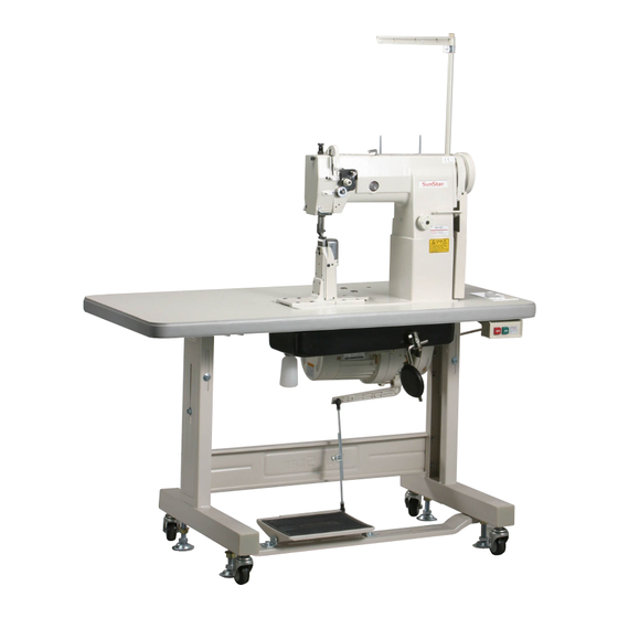
KM-857,867 Series
High post, 1,2 needle, drop
feed, needle feed, sewing
machine.
1) FOR AT MOST USE WITH EASINESS,
PLEASE CERTAINLY READ THIS MANUAL
BEFORE STARTING USE.
2) KEEP THIS MANUAL IN SAFE PLACE
FOR REFERENCE WHEN THE MACHINE
BREAKS DOWN.
M M M M E E - - 0 0 9 9 0 0 9 9 2 2 9 9
Advertisement
Table of Contents

Related Manuals for SunStar KM-857 Series


Summary of Contents for SunStar KM-857 Series
- Page 1 USER ’ ’ S MANUAL KM-857,867 Series High post, 1,2 needle, drop feed, needle feed, sewing machine. 1) FOR AT MOST USE WITH EASINESS, PLEASE CERTAINLY READ THIS MANUAL BEFORE STARTING USE. 2) KEEP THIS MANUAL IN SAFE PLACE FOR REFERENCE WHEN THE MACHINE BREAKS DOWN.
- Page 2 1. Thank you for purchasing our product. Based on the rich expertise and experience accumulated in industrial sewing machine production, SUNSTAR will manufacture industrial sewing machines, which deliver more diverse functions, high performance, powerful operation, enhanced durability, and more sophisticated design to meet a number of user’s needs.
-
Page 3: Table Of Contents
Table of Contents Safety rules for machines ..........4 1.Specifications 1) Machine types..................8 2) Specifications of the machine ............8 3) Specifications of servo motor controller...........8 (trimming type: KM-857-7, KM-867-7) 4) Specifications of clutch motor (non-trimming type: KM-857, KM-867)..........9 5) Peripheral automation devices (optional: trimming type)....9 2. -
Page 4: Safety Rules For Machines
Safety Rules for Machines Safety labels in the manual are categorized into danger, warning and caution. Failure to follow the safety rules may result in physical injuries or mechanical damages. The safety labels and symbols are defined as follows. [The meaning of the safety labels] Danger Instructions here shall be observed strictly. - Page 5 1-3) Troubleshooting If in need of troubleshooting, call a trained A/S engineer who has been educated by sunstar. ⓐ Before cleaning and repair, be sure to turn off the power supply. And wait for about 4 minutes untill the machine discharges completely.
- Page 6 1-4) Machine KM-857/867 series are manufactured for industry use to sew textiles and other similar Operation material. In case of running the machine, users should observe the following things. ⓐ Before operating the machine, read the manual and understand fully the details about its operation.
- Page 7 1-6) Position of “Caution” is adhered to the machine for safety. Caution Mark In case of starting to run the machine, read the directions of “Caution” carefully. [Position of Caution Mark] CAUTION 경 고 Do not operate without finger guard and safety devices.
-
Page 8: Specifications
Specifications 1) Machine Types Model No. Model Name KM-857 High post type 1 needle, drop feed, needle feed sewing machine (standard hook) KM-857-7 High post type 1 needle, drop feed, needle feed sewing machine with automatic trimmer (standard hook) KM-867 High post type 2 needle, drop feed, needle feed sewing machine (standard hook) KM-867-7 High post type 2 needle, drop feed, needle feed sewing machine with automatic trimmer... -
Page 9: (Trimming Type: Km-857-7, Km-867-7) 4) Specifications Of Clutch Motor (Non-Trimming Type: Km-857, Km-867)
4) Specifications of clutch motor (non-trimming type: KM-857, KM-867) MODEL VOLT WATT HERTZ HEC-1701 1 phase 220V 250W 50/60 Hz HEC-1703 3 phase 220V/380V 250W 50/60 Hz HEC-1705 3 phase 220V 400W 50/60 Hz HEC-1706 1 phase 220V 400W 50/60 Hz 5) Peripheral automation devices (optional: trimming type) Optional Device Model... -
Page 10: Installation
Installation Warning ▶Installation of the machine should be performed by a trained engineer. ▶Any electrical wiring must be performed by a qualified technician or agent. ▶The machine weighs over 53kg. At least 2 persons should carry out the installing work. ▶Plug in after the installation is complete. -
Page 11: Installation Of Oil Fan
3) Installation of oil fan ※Insert the projecting part of the oil fan ② into the respective machine holes on the lower side of the Nail table ①, and then push securely to the right. Fix the oil fan to the four fixing spots ③ using 4 nails. (see figure 3) ③... - Page 12 (2) As in figure 5, make sure to supply oil into the oil holes marked in red and into each friction part, before moving the sewing machine. [Figure 5] (3) Supply level adjustment of oil supply terminal The amount of oil supplied from the arm’s oil tank to the front and middle bushing of the lower shaft and the front busing of the horizontal push stick can be adjusted using the adjustment screw ②...
-
Page 13: Adjustment Of Belt Tension
5) Adjustment of belt tension Once the motor is installed, when the fixing nuts ①,② are fully unfastened on both sides, tension is created to the belt ④ ④ due to the weight of the motor ③. At this moment, fasten the fixing nut ①... -
Page 14: Installation Of Thread Stand
8) Installation of thread stand As seen in figure 11, fix the thread stand ① to the table using the washer and nut on the right. ① [Figure 11] 9) Synchronizer assembling and its control method (automatic trimming type) ④ ②... -
Page 15: Reverse Button Function (Automatic Trimming Type)
(2) Film adjustment of synchronizer A. For new model type (see figures 14, 15) Manually turn the pulley so that the needle bar is placed where it starts rising from the lowest point. Unfasten the film fixing screw ① in figure 15, and for “DOWN” film A, align the film adjustment base line with the sensor adjustment base line, as can be seen in ⓚ. -
Page 16: Adjustment Of The Machine
Adjustment of the machine Caution ▶In case of setting the needle, be sure to switch off the power supply. If the user steps on the pedal by mistake, the machine will start automatically, and this might lead to physical injuries. ▶When using the clutch motor, remember that the motor revolves for a while even after switching off the power supply due to inertia. -
Page 17: Winding Lower Thread
3) Winding lower thread (1) Winding the lower thread ② A) Insert the thread into the hole ①, and put it around the ① ⑤ back of tension adjustment plate ② to the front side. ⑧ B) Bring the thread towards the bobbin ③, and wind it ⑥... -
Page 18: Inserting Bobbin
5) Inserting bobbin Stop the needle ① at the highest position. Following the figure 22, insert the bobbin (where the thread is rolled onto) or the bobbin case ② into the hook ③. After laying down the bobbin holder ④, close the slide plates on the right and left ⑤. ②... -
Page 19: Adjusting Thread Tension
7) Adjusting thread tension The result of the needlework depends on the sewing conditions such as the sewing material, used thread and stitch length. So please adjust as fit. - Good sewing - Strong upper thread tension with weak lower thread tension. - Weak upper thread tension with strong lower thread tension. - Page 20 (3) Adjusting the tension of thread take up lever spring A) Adjusting the thread take up stroke As in figure 26, loosen the stopper clamp screw ①, and turn the thread take up lever spring stopper ② clockwise to make the stroke smaller and counterclockwise to make it bigger. The thread take up stroke is normally 5~10mm. B) Adjusting the thread take up tension As in figure 26, loosen the screw ③...
-
Page 21: Adjusting Height And Pressure Of The Presser Foot
(5) Adjusting the auxiliary thread tension control assembly (automatic trimming type) Short As in figure 28, when the auxiliary thread tension Long adjustment nut ① is turned clockwise, the length of the ① thread after trimming gets short. The other way makes the thread long. -
Page 22: Adjusting Needle And Feed Dog Timing
9) Adjusting needle and feed dog timing (1) After removing the needle, lay down the machine on its back and remove the timing belt ①. (2) Turn the pulley② to align the highest position ③ of the pulley’s thread take up lever with the position ④ of the arm. Then rotate the timing pulley ⑤... -
Page 23: Adjusting Needle And Hook Timing
11) Adjusting needle and hook timing (1) Fixing the height of the needle bar ※Turn the pulley to place the needle bar in the lowest position. Loosen the needle bar holding screw ①, adjust so that the needle bar carved sign ⓐ meets the end of the frame ⓑ like in figure 32, then tighten the screw. Lowest point of the needle bar when using DPx5 needle. -
Page 24: Clearance Adjustment Between Upper Side Of Hook Stopper And Upper Side Of Needle Plate Groove
(3) Adjusting the distance between the needle and the hook edge Raise the needle from its lowest point so that the hook edge meets the needle center. Like in figure 34, when the lower part of the needle meets the balance point of the hook’s needle guide plate ① (adjust the needle guide form), adjust the distance between the hook edge and the inner side of the needle groove to 0.05~0.1mm. -
Page 25: Replacing Feed Dog
14) Replacing feed dog (1) For KM-857 series, refer to figure 38 to replace the feed dog. [Figure 38] (2) Feed dog replacement method for KM-867 series is very simple, as they have adopted the ‘quick change’ type structure. Please refer to the following explanation and figure 39. -
Page 26: Adjustment Of Safety Device
15) Adjustment of safety device When there is overload in the machine during the operation, the safety device pulley ① and the lower shaft ② get separated, thereby not passing the driving power of the upper shaft to the lower shaft②. Hence major parts are protected from damage. In this case, the power switch needs to be turned off, and the cause of the overload needs to be removed. - Page 27 B) Adjusting the stopper pin holder (See figure 42) ② ⑦ Complementary straight line Trimming finishing point ⑧ ① ⑥ ⑩ ⑨ ④ ① ⑤ Movable knife operation starting point ③ [Trimming Cam Lead] (※The present stop position of the cam: roller is inside the complementary straight line with the cam lead, right before it exits having finished trimming action) [Figure 42]...
- Page 28 C) Fixing the position of the trimmer solenoid (see figure 43) a) When the whole trimmer shake linkage① is in up position, that is, when it has come back to its original position after finishing trimming, the distance④ between the lower part of the roller② and the equal point of the trimming cam ③ is about 0.8~1mm.
- Page 29 (3) Adjusting movable knife and fixed blade(See figure 45) A) Adjusting the position of movable knife and hook a) As in picture unfasten the movable knife fixing ① ③ screw ③ to adjust the movable knife so that the edge of the movable knife ① sits at the very center ⑥...
- Page 30 C) Final fixing of movable knife’s initial position (see figure 47) ② ① ⑤ ③ ⑥ ⑨ ⑫ ⑥ ⑩ ⑪ ⑧ ④ ⑦ [Figure 47] ※The standard initial assembling position of the movable knife ① is where the movable knife-edge protrudes about 0.5~1 mm ③...
- Page 31 D) Adjusting lower thread holder When the movable knife ① returns to its initial position after completing its trimming action ① ② ③ (arrow ), like in figure 48, adjust the lower ① thread holder by loosening the fixing screw ③ to ③...
-
Page 32: Replacing Movable Knife And Fixed Blade
17) Replacing movable knife and fixed blade (1) Open the hook cover (2) Loosen the screw ①, and remove the fixed blade holder ⑤ cover②. ⑥ (3) Loosen the screw ③, and disassemble the washer④ and the fixed blade⑤. ④ ⑦... - Page 33 ⑥ ⑦ ① ⑧ [Figure 53] (6) When the wiper ① is in stand-by position, the distance between the wiper edge ① and the presser bar ⑥ equal point should be about 3 mm. To do so, loosen the clamp screw⑧ and vertically adjust the stopper ⑦. ※Depending on the thread type, there are cases where the thread cannot be routed to the wiper edge.
-
Page 34: Replacing Gauge Set For Needle Width
19) Replacing gauge set for needle width (1) Disassembling order [Caution] Turn off the power switch. 1. Open the hook cover. 2. Remove the needle 3. Disassemble the needle holder (※ Turn it towards the arrowed direction for removal: KM-867 series) 4. -
Page 35: Cause Of Trouble And Troubleshooting
Cause of trouble and troubleshooting 1) Machine troubleshooting Symptom Checkpoints Root cause Corrective action Direction and height Needle is inserted into wrong Reinsert the needle correctly and of needle position push in to its highest level. Needle Needle is bent Change the needle Feed dog timing Bad timing of feed dog... - Page 36 Symptom Checkpoints Root cause Corrective action Remaining upper The length of the remaining upper Increase the adjustment volume of thread length after thread is too short the upper thread on the control box trimming After trimming, lower thread holder Adjust the location and tension of Lower thread holder does not hold the lower thread the lower thread holder.
Need help?
Do you have a question about the KM-857 Series and is the answer not in the manual?
Questions and answers