Table of Contents
Advertisement
Available languages
Available languages
Quick Links
Advertisement
Table of Contents

Related Manuals for Griven AL2500


Summary of Contents for Griven AL2500
- Page 1 GoboLED 80 AL2500 Manuale di istruzioni Instructions manual...
-
Page 2: Table Of Contents
INDICE 1.0 Introduzione ..............4 1.1 Informazioni di sicurezza . - Page 3 INDEX 1.0 Introduction ..........................20 1.1 Safety information..............................20 1.1.1 Protecting against electric shock ........................20 1.1.2 Installation ..............................20 1.1.3 Protection against burns and fire .........................20 1.1.4 Weather protection............................20 1.1.5 Forced ventilation............................20 1.2 Warranty conditions...............................20 1.3 Compliance ................................20 2.0 Size ...............................21 3.0 Components of the unit......................21 4.0 Quick turn on..........................22 5.0 Packaging and transport ......................23 5.1 Packaging ................................23...
-
Page 4: Introduzione
• GRIVEN Srl garantisce la buona qualità e realizzazione dei propri prodotti e si impegna a riparare o sostituire a propria discrezione, nel più breve tempo possibile, qualsiasi parte che – durante il periodo di garanzia – mostri difetti di costruzione, assemblaggio o materiale. -
Page 5: Dimensioni
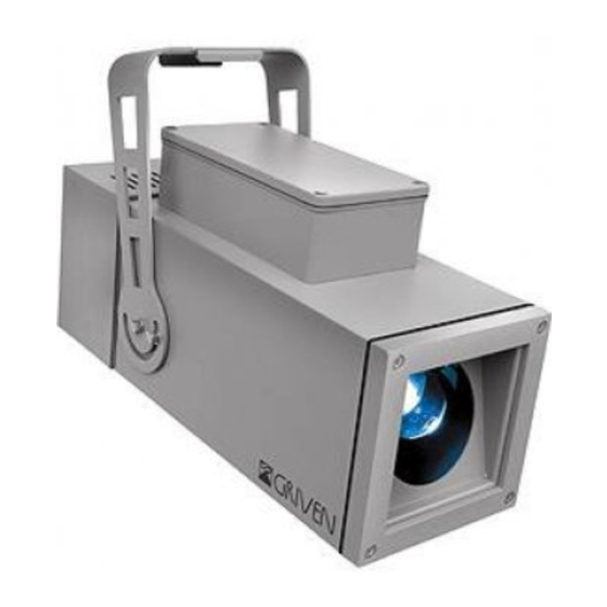
2.0 Dimensioni 164mm 152mm 273mm 10.8" 6.5" 6" 425.3mm 16.7" 3.0 Componenti del proiettore Descrizione componenti: A. Corpo proiettore B. Gruppo ottica C. Gruppo schede D. Forcella E. Gruppo ventola Italiano... -
Page 6: Avviamento Rapido
4.0 Avviamento rapido In questo capitolo troverete elencate brevemente le operazione necessarie per utilizzare immediatamente il proiettore. Queste istruzioni sono indispensabili per la connessione e l’alimentazione dell’apparecchio, ma non descrivono in modo completo le sue funzionalità. Vi invitiamo quindi a leggere anche gli altri capitoli di questo manuale, in modo da apprendere tutte le informazioni relative al proiettore. -
Page 7: Imballo E Trasporto
1 manuale di istruzioni Attenzione! • La responsabilità di Griven S.r.l. cessa all’atto della consegna del materiale al vettore: reclami per eventuali danni dovuti al trasporto dovranno essere indirizzati direttamente al corriere. • Si accettano reclami entro e non oltre i 7 giorni dal ricevimento della merce. -
Page 8: Installazione
6.0 Installazione 6.1 Fissaggio Il proiettore può essere utilizzato sia appoggiato a terra che fissato ad una struttura e può funzionare in qualsiasi posizione. Utilizzare i fori “4” Ø10.5 (0.4”) per fissare l’apparecchiatura. 6.2 Orientamento del fascio di luce A. Allentate le viti laterali “5”. B. -
Page 9: Collegamento Della Tensione Di Alimentazione
6.3 Collegamento della tensione di alimentazione Il proiettore può funzionare con tensioni da 90 a 250Vac e con frequenze di 50 e 60Hz. Non è necessario nessun tipo di intervento. Il proiettore si regola automaticamente in base alla tensione e fre- quenza rilevata. -
Page 10: Collegamento Del Segnale Dmx
C. Richiudete il proiettore riavvitando le viti “L” rimosse in prece- denza. 6.4 Collegamento del segnale DMX Il segnale DMX deve essere collegato utilizzando un cavo schermato progettato per congegni RS-485. Il proiettore è dotato di morsetti interni per la connesione del cavo di segnale DMX, come indicato nelle figure seguenti. -
Page 11: Installazione Del Gobo
Attenzione! La schermatura ed i conduttori non devono fare alcun tipo di contatto tra loro o con la custodia metallica dei connettori. Il pin numero 1 e la custodia non devono essere collegate alla massa elettrica dell’apparecchio. Nell’ultima apparecchiatura della linea DMX inserite una resistenza da 120 Ω collegata ai pin Data- e Data+. C. -
Page 12: Zoom E Messa A Fuoco
C. Insertite il gobo nella sede “13”. D. Bloccate il gobo utilizzando la molla “14”. E. Richiudete il proiettore riavvitando le viti “11” rimosse in precedenza. 6.6 Zoom e messa a fuoco A. Svitate le viti “11” e rimuovete il coperchio inferiore. Italiano... - Page 13 B. Regolate l’angolo di proiezione spostando le lenti e blocca- tele poi avvitando i relativi pomoli “12”. C. Richiudete il proiettore riavvitando le viti “11” rimosse in precedenza. Goboled 80 può proiettare immagini con un angolo da 17° a 28° di apertura. Italiano...
-
Page 14: Utilizzo Del Proiettore
7.0 Utilizzo del proiettore 7.1 Impostazione modo di funzionamento Mediante il pannello dip-switch è possibile selezionare uno dei seguenti modi di funzionamento: • Con controllo DMX512 Il proiettore viene controllato tramite segnale DMX512. • In modalità MASTER-SLAVE o AUTOMATICA I proiettori funzionano in modo indipendente senza bisogno di centraline di controllo (vedi capitolo 8.0 Funzionamento Master-Slave e Automatico). -
Page 15: Funzioni Dmx
7.3 Funzioni DMX Canale Funzione Valore Descrizione 0-31 Nessun effetto 32-55 Rotazione oraria velocità 1 56-79 Rotazione oraria velocità 2 80-103 Rotazione oraria velocità 3 104-127 Rotazione oraria velocità 4 Rotazione Gobo 128-151 Rotazione antioraria velocità 4 152-175 Rotazione antioraria velocità 3 176-199 Rotazione antioraria velocità... -
Page 16: Configurazione Master
8.1 Configurazione MASTER Per eseguire un programma preimpostato è sufficiente portare il dip-switch Master su ON e scegliere il tipo di programma da eseguire. Nelle figure seguenti sono riportati alcuni esempi di configurazione di proiettori MASTER. Proiettore Master (Master = ON) con programma 1°... -
Page 17: Configurazione Automatico
11.0 Parti di ricambio Tutti i componenti del proiettore sono disponibili come parti di ricambio presso i rivenditori Griven. Le viste esplose, lo schema elettrico e il diagramma elettronico sono disponibili su richiesta. Per facilitare il lavoro del centro di assistenza ricordate di specificare il numero di serie ed il modello del proiettore di cui avete richiesto i ricambi. -
Page 18: Ricerca Dei Guasti
12.0 Ricerca dei guasti Problema Possibile causa Provvedimento Apparecchiatura non Controllate che i cavi di alimentazione siano collegati e alimentata. che ci sia tensione. Il proiettore non si accende. Scheda guasta. Verificare il funzionamento della scheda di controllo. Collegamento cavi Ispezionare connessioni e cavi. -
Page 19: Specifiche Tecniche
14.0 Specifiche tecniche Caratteristiche meccaniche Altezza ................280.5mm (11”) Larghezza . -
Page 20: Introduction
• The guarantee excludes all consumables. • The customer will take care of the return of the faulty parts to GRIVEN srl of Italy, at his own charge and risk. • The parts which have been repaired or replaced are sent by GRIVEN srl of Italy ex-factory. -
Page 21: Components Of The Unit
2.0 Size 164mm 152mm 273mm 10.8" 6.5" 6" 425.3mm 16.7" 3.0 Components of the unit Components description: A. Body B. Optic group C. PCB group D. Bracket E. Fan group English... -
Page 22: Quick Turn On
4.0 Quick turn on In this chapter brief essential instructions for an immediate use of the unit are listed. These instructions are neces- sary to connect and power up the unit, but they will not describe in complete details the functions of the unit it- self. -
Page 23: Packaging And Transport
• Griven S.r.l. will accept claims for broken or missing goods only within seven days of receipt of the goods. • Returns of equipment will not be accepted without prior authorization granted by Griven S.r.l. and if not duly ac- companied by relevant shipping documents. -
Page 24: Fixing
6.0 Installation 6.1 Fixing The unit can be used both rested on floor and fixed onto a structure. The unit can operate in any position. Use the holes “4” Ø10.5 (0.4”) in the bracket to fix the unit. 6.2 Adjusting light beam direction A. -
Page 25: Connection To Mains Power
6.3 Connection to mains power The unit can operate with voltage from 90 to 250Vac and with frequency of 50 and 60Hz. It is not necessary to effect any setup procedures. The fixture will automatically adjust its operation to suit any fre- quency or voltage within this range. -
Page 26: Connection To Dmx Signal
C. Close the unit again by tighten the screw “6” previously re- moved. 6.4 Connection to DMX signal The DMX signal is to be connected by using a shielded cable designed for devices RS-485. The unit is fitted with internal pins for the connection of the of the DMX signal cable, as shown in the following pictures. -
Page 27: Gobo Installation
Warning! All data wires must be isolated one from another, from the shield and from the metal housing of the connectors. Pin number 1 of the housing is not to be connected to the electric ground of the unit. Insert a 120 Ω resistor connected to Data+ and Data- in the last unit. C. - Page 28 C. Insert the gobo in the gear “13”. D. Block the gobo by using the spring “14”. E. Close the unit again by tighten the screw “11” previously re- moved. 6.6 Focus and zoom A. Untighten the screw “11” and remove the lower cover. English...
- Page 29 B. Move the lenses on order to adjust the beam angle and then tighten the knob “12”. C. Close the unit again by tighten the screw “11” previously removed. Goboled 80 produces an manually adjustable beam between 17° and 28°. English...
-
Page 30: Setting Operating Mode
7.0 Use of the unit 7.1 Setting operating mode By the dip-switch set it is possible to select one of the following operating modes: • using DMX512 signal control mode Each fixture is controlled from DMX512 signal control. • MASTER-SLAVE or AUTOMATIC mode The projector operates independently, without DMX512 signal control. -
Page 31: Dmx Functions
7.3 DMX functions Channel Function Value Description 0-31 No effect 32-55 Clockwise rotation speed 1 56-79 Clockwise rotation speed 2 80-103 Clockwise rotation speed 3 104-127 Clockwise rotation speed 4 Gobo rotation 128-151 Counterclockwise rotation speed 4 152-175 Counterclockwise rotation speed 3 176-199 Counterclockwise rotation speed 2 200-223... -
Page 32: Master Configuration
8.1 MASTER configuration To execute a preset programme set the dip-switch Master to ON and choose the type of programme to be executed. The following pictures show some examples of MASTER units configuration. Unit set as Master (Master = ON) program 1 running (dip-switch 1 = ON) 1 2 3 4 5 6 7 8 9 10 11 12 Unit set as Master (Master = ON) -
Page 33: Maintenance
• Check that the unit is not damaged mechanically. Replace those components which have got deteriorated. 11.0 Spare parts All components of the unit are available as spare parts at Griven dealers. Exploded views, wiring diagrams, electronic layouts and advertising brochures are available on request. -
Page 34: Troubleshooting
12.0 Troubleshooting Inconvenience Possibile Cause Action Check that the power supply cable is connected and the Unit not powered up. unit is powered. The fixture will not turn Out of order PCB Check the PCB functions. Incorrect DMX cable Check connections and wires. Rectify inefficient connec- connection. -
Page 35: Technical Specifications
14.0 Technical specifications Mechanical features Height ................280.5mm (11”) Width . - Page 36 Via Bulgaria, 16 - 46042 CASTEL GOFFREDO (MN) - Italy Telefono 0376/779483 - Fax 0376/779682 - 0376/779552 http://www.griven.com/ e-mail griven@griven.com http://www.griven.it/ e-mail griven@griven.it User’s manual rel. 1.01...
Need help?
Do you have a question about the AL2500 and is the answer not in the manual?
Questions and answers