Table of Contents
Advertisement
Quick Links
Advertisement
Table of Contents

Related Manuals for Riva RC4100-IN


Summary of Contents for Riva RC4100-IN
-
Page 1: Installation Guide
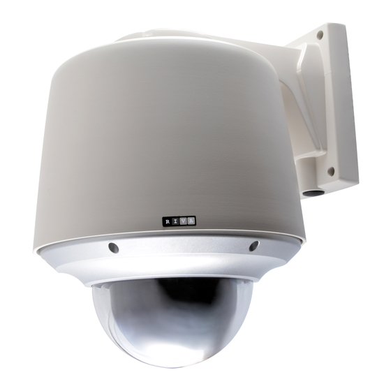
RC4100-IN/ RC4100-OUT Installation Guide (RC4100-Out is an Outdoor PTZ Camera, Adding an Outdoor Housing to Indoor PTZ RC4100-IN) IMPORTANT! The explanation and specification at this manual are mainly on the basis of RC4100-2212-36 which uses Sony 36X Optical Zoom module. -
Page 2: Information To User
INFORMATION TO USER CAUTION RISK OF ELECTRIC SHOCK, DO NOT OPEN CAUTION: TO REDUCE THE RISK OF ELECTRIC SHOCK, DO NOT REMOVE COVER (OR BACK). NO USER SERVICEABLE PARTS INSIDE. REFER SERVICING TO QUALIFIED SEERIVCE PERSONEL. This symbol is intended to alert the user to the presence of un- insulated “dangerous voltage”... -
Page 3: Table Of Contents
Table of Contents 1. FEATURES…………………………………………………………………………7 2. PACKAGE CONTENTS ………………………………………………………….8 3. PART NAMES…………………………………………………………………….9 4. INSTALLATION…………………………………………………………………..12 4.1. Setting the Image Attribute ............13 4.2.Operating the OSD Menu ............... 13 5. CONNECTIONS………………………………………………………………….14 5.1.Connectors ................. 14 CONFIGURATION………………………………………………………………..20 6.1.Set up network environment ............20 6.2.View video on web page ..............20 6.2.1. - Page 4 APPENDIX (C): ACCESSORIES…………………………………………………...29 Outdoor part ..................29 Assembling outdoor housing ..............30 APPENDIX (D): HEXADECIMAL-DECIMAL CONVERSION TABLE…………..33 REVISION HISTORY…………………………………………………………………34 www.rivatech.de...
-
Page 5: Features
1.FEATURES Camera Indoor / Outdoor PTZ Dome IP Camera IP66 vandal proof (supported only with Outdoor Housing) Sony 1/4” Exview HAD CCD x36 Optical Zoom, x12 Digital Zoom True Day & Night (IR Cut Filter) +DSS Streaming ... -
Page 6: Package Contents
2. PACKAGE CONTENTS Unpack carefully and handle the equipment with care. The packaging contains: Camera Ceiling Mount Bracket Ceiling Cover Screws Wrench Terminal block (2Pin, 3Pin , 5Pin ,6Pin) Safety Wire Cable Ties Quick Installation Guide The above contents are subject to change without prior notice. Note www.rivatech.de... -
Page 7: Part Names
3.PART NAMES Bubble Lock Screw Dip Switch Camera Lens Lock Holder Ceiling Mount Bracket for indoor www.rivatech.de... - Page 8 ALARM ⑥ ⑤ GND 1 4 GND ④ ⑦ LINE OUT ① VIDEO MIC/ LINE IN 100 BaseT ⑨ ② RS 485 AC24V ⑧ ③ * Models herein and their appearance are subject to change without any prior notice. www.rivatech.de...
- Page 9 1 LAN Connector (Ethernet) This is a RJ45 LAN connector for 10/100 Base-T Ethernet. LED1 LED2 This LED lights up as orange and turns green when the encoder is powered on. LED operation setting: For the factory default setting, LED 2 blinks for the heartbeat and LED 1 turns on for 4.5.11.
-
Page 10: Installation
4.INSTALLATION 147.0 mm SAFETY WIRE SCREW(Ø4.0) COVER HOLE CELING BRACKET LOCK HOLDER 1 SAFETY WIRE HOLE MOUNTING HOLE Before you install the camera, you should set the DIP switches to configure the camera ID, communication protocol. Please refer to the page15. DIP Switch 1. -
Page 11: Setting The Image Attribute
LOCK HOLDER.1 SCREW (M3.0) 10° LOCK HOLDER.2 6. Make the wires go through the square hole. 7. Insert mount holder and twist the camera counterclockwise. COVER 8. Fix the camera by driving a screw on lock holder1 and 2. COVER HOLE 9. -
Page 12: Connections
5.CONNECTIONS 5.1.Connectors IR SENSOR or DOOR SENSOR AUX 1 SIGNAL AUX 2 TERMINAL BLOCK (FEMALE) LINE OUT LAN CABLE 100 BaseT MIC/ LINE IN MONITOR RS 485 LINE OUT MIC IN RS-485 Serial Device AC24V ADAPTOR AC220/110V Power Connection Please, check the voltage and current capacity of rated power carefully. Rated power is indicated in the back of main unit. - Page 13 Connect to the audio input device such as a Mic and the audio output device such as the amplifier speaker. Do not connect the speaker without amplifier. Caution Sensor (DI) connection The camera provides 4 channel D/I. It can be connected to a relay type sensor as the following figures.
- Page 14 Internal Device Relay Type DIP Switch Before you install the camera, you should set the DIP switches to configure the camera ID, communication protocol. www.rivatech.de...
- Page 15 Opening dome cover 2 mm UNLOCK 1 2 3 4 5 6 1 2 3 4 5 6 Unlock the screw Rotate the cover to remove DIP1 - Camera ID DIP 2 - RS485, PTZ protocol, Baud rate Placing dome cover Place dome cover and rotate to tighten Lock the screw www.rivatech.de...
- Page 16 Camera ID Setup ID number of camera is set using binary number. The example is shown bellow. DIP1 ID Value Default ex) ID=10 The range of ID is 1~255. Do not use 0 as camera ID. Factory default of Camera ID is If you want to control a certain camera, you must match the camera ID with Cam ID setting of DVR or Controller.
- Page 17 Pin3 Pin4 Protocol Pelco-D or Pelco-P Not used Maxpro Pin7 Pin8 BAUD RATE Not Used 2400bps (Pelco-D) 4800bps (Pelco-P) 9600bps (Maxpro) If you want to control using DVR or P/T controller, their protocol must be identical to camera. Otherwise, you cannot control the camera. If you changed camera protocol by changing DIP S/W, the change will be effective after you reboot the camera.
-
Page 18: Configuration
6.CONFIGURATION 6.1.Set up network environment The default IP address of your IP device is 192.168.XXX.XXX. You can find the available IP address from the MAC address of your device. Please make sure the device and your PC are on the same network segment before running the installation. If the network segment between your PC and the device is different, change your PC’s settings as below. - Page 19 To use the IPAdminTool and view the live video on a web page: 1. Start IPAdminTool. Names and info of currently activated IP devices appear as a list. 2. Right-click on the desired device and select Web view. 3. Click pop-up blocked and install the ActiveX setup.exe by clicking the Run or Save button.
-
Page 20: View Video Using Ip Address
6.2.2. View video using IP address View the live video on a web page using your IP device and its IP address. To have the correct IP address ready and use it on a web page: 1. Convert a MAC address to an IP address or check the IP address on the Appendix (D): Hexadecimal-Decimal Conversion Table IPAdminTool. -
Page 21: Appendix (A): Specifications
APPENDIX (A): SPECIFICATIONS Summary The explanation and specification at this manual are mainly on the basis of the specific camera model, which uses Sony 36X Optical Zoom module. Camera Module Sony 1/4” Exview HAD Samsung 1/4" Interline Transfer CCD Image Sensor Effective Pixels NTSC 768(H) * 494(V) 380K / PAL 752(H) * 582(V) 440K TV System... - Page 22 Manual 0.5°~ 100 or 200°/sec (64step) Speed Preset Max 300°/sec , Min 10°/sec Tilt Rotation -2°~ 90° Angle Manual 0.5°~ 45°/sec (64step) Tilt Speed Preset Max 250°/sec , Min 200°/sec System 0.024° Accuracy Dome Horizontal Angle of View 57.8° (Wide end) to 1.7° (Tele end) (Approx.) 165 positions with 16 character labels / Preset...
-
Page 23: Electrical Characteristics
Network 10/100 Base-T DI / DO 4 / 2 CH RS-485 Supported SD Memory Supported (microSD type) Card Slot TCP/IP, UDP/IP, HTTP, RTSP, RTCP, RTP/UDP, RTP/TCP, Protocol SNTP, mDNS, UPnP, SMTP, SOCK, IGMP, DHCP, FTP, DDNS, SSL v2/v3, IEEE 802.1X, SSH, SNMP v2/v3 Mechanical Motor Type Stepping motor... -
Page 24: Environment Condition
Environment Condition Fan / Heater Supported via Outdoor Housing Operating -10 ℃ ~ 50 ℃ (14 ℉ ~ 122 ℉) (Dome) Temperature -40 ℃ ~ 50 ℃ (-40 ℉ ~ 122 ℉) (with Outdoor Housing) Storage Temperature -20 °C ~ 60 °C (-4°F ~ 140 °F) Operating Humidity Up to 85% RH (Non-condensing) Certification... -
Page 25: Appendix (B): Dimensions
APPENDIX (B): DIMENSIONS Dome (Unit: mm) www.rivatech.de... -
Page 26: Outdoor Housing
Outdoor Housing (Unit: mm) www.rivatech.de... -
Page 27: Appendix (C): Accessories
APPENDIX (C): ACCESSORIES Outdoor part Sun Visor Housing Circuit Board Cover Mount Bracket www.rivatech.de... -
Page 28: Assembling Outdoor Housing
Assembling outdoor housing Attach the mount bracket to the dome camera. Find more explanation at NOTE A below. Cover Open the dome cover to remove the bubble. Find more explanation at NOTE B below. Twist the bubble counterclockwise and remove it from the dome cover. - Page 29 Dome Camera with Mount Bracket NOTE A. Before you assemble the dome camera and its outdoor housing, you should attach the mount bracket to the dome camera. For the detailed information, please refer to the 4.INSTALLATION NOTE B. when you remove the bubble, you should open the dome cover first.
- Page 30 There is a bimetal implemented in the outdoor housing for controlling the fan and heater. Refer to its specification below for more details. Bimetal for Heater Activation 35°C-OFF / 45°C-ON 15°C-OFF / 5°C-ON Part Number Package DIP Type DIP Type Maker Korea Bitec Korea Bitec...
-
Page 31: Appendix (D): Hexadecimal-Decimal Conversion Table
APPENDIX (D): HEXADECIMAL- DECIMAL CONVERSION TABLE Refer to the following table when you convert the MAC address of your device to IP address. Hex Dec Hex Dec Hex Dec Hex Dec Hex Dec Hex Dec Hex Dec B9 185 6F 111 94 148 DE 222 70 112... -
Page 32: Revision History
REVISION HISTORY MAN# DATE(M/D/Y) Comments 01A.00 15/07/2009 Created. 01A.01 08/24/2009 Added the requirement of VCA : MSXML4.0 01A.02 09/25/2009 Added Operation the OSD menu Added Setting the Image Attribute 01A.03 09/29/2009 Changed the VCA specification 01A.04 10/15/2009 Added the Cross Reference 01A.05 11/16/2009 Added the assembling Outdoor housing 01A.06...
Need help?
Do you have a question about the RC4100-IN and is the answer not in the manual?
Questions and answers