Table of Contents
Advertisement
Quick Links
Advertisement
Table of Contents

Related Manuals for ACME LED-ST50


Summary of Contents for ACME LED-ST50
-
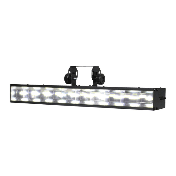
Page 1: User Manual
LED-ST50 User Manual Please read the instruction carefully before use... -
Page 2: Table Of Contents
CONTENTS 1. Safety Instructions ....................2 2. Technical Specifications ..................4 3. How To Set The Unit ....................5 3.1 Control panel ....................5 3.2 Main Function ....................6 4. How To Control The Unit ..................11 4.1 Master/Slave Built In Preprogrammed Function ..........11 4.2 Easy Controller .................... -
Page 3: Safety Instructions
1. Safety Instructions Please read carefully the instruction, which includes important information about the installation, usage and maintenance. WARNING Please keep this User Guide for future consultation. If you sell the unit to another user, be sure that they also receive this instruction booklet. ... - Page 4 Warning: To prevent or reduce the risk of electrical shock or fire, do not expose the unit to rain or moisture. DO NOT open the unit within five minutes after switching off. The housing, the lenses, or the ultraviolet filter must be replaced if they are visibly damaged. Caution: There are no user serviceable parts inside the unit.
-
Page 5: Technical Specifications
2. Technical Specifications 4 DMX Channel Modes: 1/2/10/12 Channels 3 operation modes: DMX512, Master/Slave and Sound Active. Variable strobe speed and intensity can be adjustable by knobs. Great built-in lighting shows under Master/Slave mode triggered by music. Optional CA-8 for instant lighting shows. Smooth 0~100% dimming and variable strobe speeds. -
Page 6: How To Set The Unit
3. How To Set The Unit 3.1 Control panel 1. FUSE(T 2A): Protect the unit from the damage of the over current. 2. POWER IN: Connect to power supply. 3. POWER OUT: Connect to supply power for the next unit. 4. -
Page 7: Main Function
16. ONLY FOR REMOTE CONTROL: Connecting with CA-8 to control the unit for Stand by, Function and Mode function. 17. DMX INPUT: For DMX512 link, use 3-pin XLR cable to link the unit together. 18. DMX OUTPUT: For DMX512 link, use 3-pin XLR plug cable to link the next unit. 3.2 Main Function To select any of the given functions, press the MENU button up to when the required one is showing on the display. - Page 9 DMX 512 ADDRESS To select the , press the ENTER button to show the DMX ADDRESS on the display. Use the DOWN/UP button to adjust the address from 1 to 512. Once the address has been selected, press the ENTER button to setup, to go back to the functions without any changes press the MENU button again.
- Page 10 MANUAL MODE To select the , press the ENTER button to show the MANUAL MODE on the display. Use the DOWN/UP button to select the (Dimmer) or (Strobe). Once the mode has been selected, press the ENTER button, and use the DOWN and UP button to adjust the value (0-255). Once selected, press the ENTER button to setup, to go back to the functions without any changes press the MENU button again.
- Page 11 DISPLAY INVERSE To select the , press the ENTER button to show the DISPLAY on the display. Use the DOWN/UP button to select the (normal) or (inversion), press ENTER button to setup. Back to the functions without any change press MENU button. AUTO TEST To select the , press the ENTER button to show the TEST on the display and the unit will run...
-
Page 12: How To Control The Unit
4. How To Control The Unit You can operate the unit in three ways: 1. Master/slave built-in preprogram function 2. Easy controller 3. Universal DMX controller No need to turn the unit off when you change the DMX address, as new DMX address setting will be effect at once. -
Page 13: Dmx Controller
first unit will control all the other units for Stand by, Function and Mode selection. Blackout Blackout the unit Synchronous Strobe by auto Select Show 1 – 12 Function Synchronous Strobe by sound Manual mode (press and hold the button) Sound Show Mode... -
Page 14: Dmx 512 Configuration
5. DMX 512 Configuration 1/2 Channels Mode:... - Page 15 10 Channels Mode: 12 Channels Mode:...
-
Page 16: Dmx512 Connection
6. DMX512 Connection 1. If you using a controller with 5 pins DMX output, you need to use a 5 to 3 pin adapter-cable. 2. At last unit, the DMX cable has to be terminated with a terminator. Solder a 120 ohm 1/4W resistor between pin 2(DMX-) and pin 3(DMX+) into a 3-pin XLR-plug and plug it in the DMX-output of the last unit. -
Page 17: Troubleshooting
7. Troubleshooting Following are a few common problems that may occur during operation. Here are some suggestions for easy troubleshooting: A. The unit does not work, no light and the fan does not work 1. Check the connection of power and main fuse. 2. -
Page 18: Fixture Cleaning
8.Fixture Cleaning The cleaning of optical lenses or mirrors must be carried out periodically to optimize light output. Cleaning frequency depends on the environment in which the fixture operates: damp, smoky or particularly dirty surrounding can cause greater accumulation of dirt on the unit’s optics. ... -
Page 19: Declaration Of Conformity
Declaration of Conformity We declare that our products (lighting equipments) comply with the following specification and bears CE mark in accordance with the provision of the Electromagnetic Compatibility (EMC) Directive 89/336/EEC. EN55103-1: 2009 ; EN55103-2: 2009; EN62471: 2008; EN61000-3-2: 2006 + A1:2009 + A2:2009; EN61000-3-3: 2008. &... - Page 20 Innovation, Quality, Performance...
Need help?
Do you have a question about the LED-ST50 and is the answer not in the manual?
Questions and answers