Dell Latitude 12 Rugged Extreme 7214 Owner's Manual
Hide thumbs
Also See for Latitude 12 Rugged Extreme 7214:
- Getting started manual (111 pages) ,
- Getting started manual (25 pages) ,
- Getting started manual (24 pages)

Related Manuals for Dell Latitude 12 Rugged Extreme 7214


Summary of Contents for Dell Latitude 12 Rugged Extreme 7214
- Page 1 Dell Latitude 12 Rugged Extreme – 7214 Owner's Manual Regulatory Model: P18T Regulatory Type: P18T002...
- Page 2 © 2016 Dell Inc. All rights reserved. This product is protected by U.S. and international copyright and intellectual property laws. Dell and the Dell logo are trademarks of Dell Inc. in the United States and/or other jurisdictions. All other marks and names mentioned herein may be trademarks of their respective companies.
-
Page 3: Table Of Contents
Contents 1 Working on your computer................8 ....................8 Before working inside your computer ........................9 Turning off your computer ..................9 Turning off your computer — Windows 10 ..................9 Turning off your computer — Windows 8 ..................10 Turning off your computer — Windows 7 ....................10 After working inside your computer ...................... - Page 4 ....................27 Removing the power button board ......................28 Installing the power button board ......................28 Removing the docking board ....................... 29 Installing the docking board ..................... 29 Removing the antenna routing bracket ....................30 Installing the antenna routing bracket ........................30 Removing the WLAN card ........................
- Page 5 ............................55 Processors ..................55 Identifying processors in Windows 10 ....................55 Identifying processors in Windows 8 ....................56 Identifying processors in Windows 7 ................56 Verifying the processor usage in Task Manager ..............57 Verifying the processor usage in Resource Monitor ............................... 58 Chipsets ....................
- Page 6 5 System Setup....................... 70 ............................70 Boot Sequence ........................... 70 Navigation keys ........................71 System Setup overview ........................71 General screen options ..................72 System Configuration screen options ........................74 Video screen options .........................75 Security screen options ......................77 Secure Boot screen options ......................77 Performance screen options ....................
- Page 7 8 General troubleshooting...................93 9 Contacting Dell....................95...
-
Page 8: Working On Your Computer
Damage due to servicing that is not authorized by Dell is not covered by your warranty. Read and follow the safety instructions that came with the product. -
Page 9: Turning Off Your Computer
If the computer is connected to a docking device (docked), undock it. CAUTION: To disconnect a network cable, first unplug the cable from your computer and then unplug the cable from the network device. Disconnect all network cables from the computer. Disconnect your computer and all attached devices from their electrical outlets. -
Page 10: Turning Off Your Computer - Windows 7
CAUTION: To avoid damage to the computer, use only the battery designed for this particular Dell computer. Do not use batteries designed for other Dell computers. Connect any external devices, such as a port replicator or media base, and replace any cards, such as an ExpressCard. -
Page 12: System Overview
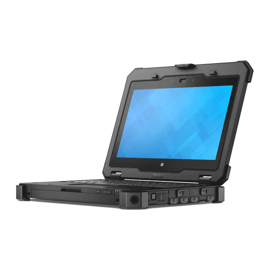
System overview System top view Figure 1. System top view display latch keyboard contactless smart card reader handle touchpad... -
Page 13: System Front View
System front view Figure 2. System front view microphone camera (optional) microphone rotatable outdoor readable display/ touchscreen flip hinge wireless status light hard drive activity light battery status light power status light volume buttons screen rotate button... -
Page 14: System Back View
System back view Figure 3. System back view security cable slot network port USB 2.0 port serial port VGA port power connector... -
Page 15: System Base View
System base view Figure 4. System base view back camera camera flash radio frequency pass-through connectors service tag docking device connector battery... -
Page 16: System Side View
System side view Figure 5. System side view — right power button fingerprint reader hard drive memory card reader/ Express card reader (optional) secure card reader Figure 6. System side view — left audio port SIM card slot HDMI port USB 3.0 port with PowerShare stylus QuadCool sealed thermal chamber... - Page 17 WARNING: Do not block, push objects into, or allow dust to accumulate in the air vents. Do not store your Dell computer in a low-airflow environment, such as a closed briefcase, while it is running. Restricting the airflow can damage the computer. The computer turns on the fan when the computer gets hot.
-
Page 18: Removing And Installing Components
Removing and installing components This section provides detailed information on how to remove or install the components from your computer. Recommended tools The procedures in this document require the following tools: • Small flat blade screwdriver • Phillips #0 screwdriver •... -
Page 19: Installing The Stylus And Tether
WARNING: Using an incompatible battery may increase the risk of fire or explosion. Replace the battery only with a compatible battery purchased from Dell. The battery is designed to work with your Dell computer. Do not use a battery from other computers with your computer. -
Page 20: Removing The Base Cover
Removing the base cover Follow the procedures in Before Working Inside Your Computer. Remove battery. To remove the base cover: a. Remove the screws that secure the base cover [1]. b. Lift the base cover to remove it from the computer chassis [2]. Installing the base cover Place the base cover on the base of the computer. -
Page 21: Installing The Keyboard And Keyboard Door
To remove the keyboard door: a. Remove the screws that secure the keyboard door [1]. b. Lift the keyboard door [2]. c. Remove the tape that secures the keyboard cables [3]. d. Disconnect the keyboard cables from the system board connector by pressing the locking tab and lifting the connector [4, 5]. -
Page 22: Removing The Hard Drive
Tighten the screws that secure the keyboard door to the computer chassis. Align the keyboard into its slot on the computer. Tighten the screws that secure the keyboard to the computer. Install the battery Follow the procedures in After Working Inside Your computer. -
Page 23: Installing The System Fan
a. Disconnect the system fan cable from the system board [1]. b. Remove the screws that secure the system fan to the computer chassis [2]. c. Lift and remove the system fan from the computer chassis [3]. Installing the system fan Align the system fan in its position in the chassis. -
Page 24: Installing The Mems Board
Installing the MEMS board Place the MEMS board in the slot. Tighten the screws that secure the MEMS board. Connect the cable to the MEMS board. Install: base cover battery Follow the procedures in After Working Inside Your computer. Removing the USH board Follow the procedures in Before Working Inside Your Computer. -
Page 25: Installing The Ush Board
Installing the USH board Connect the smart card cable to the USH board at the bottom of the board. Flip the USH board to replace it to its original position. Tighten the screws that secure the USH board. Connect the cables to the USH board. Install: base cover battery... -
Page 26: Installing The Global Positioning System (Gps) Module
Installing the Global Positioning System (GPS) module Insert the GPS module into its slot and press the latch to secure it. Connect the cable to the connector on the GPS module. Connect the antenna cable to the GPS module Affix the tape that secures the antenna cable. Connect the USH cable to the connector on the GPS module. -
Page 27: Installing The Fingerprint Reader
Installing the fingerprint reader Insert the fingerprint reader board into the slot on the computer. Connect the fingerprint reader board cable to the connector. Secure the cover to fingerprint reader board by using the screws. Install the: battery Follow the procedure in After working inside your computer. -
Page 28: Installing The Power Button Board
Installing the power button board Align the power button board with the connector on the system board. Tighten the screws that secure the power button board. Connect the cable to the power button board. Place the cover. Tighten the screws that secure the cover. Install the: battery Follow the procedure in... -
Page 29: Installing The Docking Board
Installing the docking board Connect the docking board connector cable to the system board. Flip the docking board and place it on the slot. Tighten the screws that secure the docking board. Connect the antenna cables to the docking board. Install: base cover battery... -
Page 30: Installing The Antenna Routing Bracket
Installing the antenna routing bracket Place the antenna routing bracket in the slot on the computer chassis. Tighten the screws that secure the cable holder. Route the antenna cables into the routing channels. Connect all the wireless antenna cables to the connectors. Affix the tape that secures the wireless antenna cables. -
Page 31: Installing The Wlan Card
Installing the WLAN card Insert the WLAN card in the slot. Tighten the screw that secures the WLAN card. Connect the antenna cables to the WLAN card. Install: antenna routing bracket base cover battery Follow the procedures in After Working Inside Your Computer. -
Page 32: Installing The Wwan Card
Installing the WWAN card Slide the WWAN card into its connector on the system board. Press the card and tighten the screw that secures the WWAN card. Connect the antenna cables to the WWAN card, as per the colors on the connectors. Affix the tape that secures the antenna cables. -
Page 33: Installing The Heatsink
To remove heatsink: a. Loosen the screws that secure the heatsink to the system board in the sequence shown [1, 2, 3, NOTE: The screws are retained by the heatsink and should not be fully removed. b. Lift and remove the heatsink assembly from the computer chassis [5]. Installing the heatsink Clean the old thermal grease and re-apply the grease at the base of the heatsink. -
Page 34: Removing The Coin Cell Battery
Affix the tape that secures the heatsink assembly. Route the antenna cable and connect it to the connector on the WLAN card. Affix the tape that secures antenna cable. Install: docking board base cover battery Follow the procedures in After Working Inside Your Computer. -
Page 35: Removing The Memory Module
Removing the memory module Follow the procedures in Before Working Inside Your Computer. Remove: battery base cover docking board To remove the memory module shield: a. Lift the metal tabs to remove the memory module shield [1]. b. Lift and remove the memory module shield [2]. To remove the memory module: a. -
Page 36: Installing The Memory Module
Installing the memory module Insert the memory module into the memory socket. Press the memory module down until it clicks into place. Place the memory module shield. Install: docking board base cover battery Follow the procedures in After Working Inside Your computer. -
Page 37: Installing The Sim Board
Installing the SIM board Insert the SIM board into the slot on the computer. Install the screws that secure the SIM board. Connect the SIM board connector cable to the SIM board. Install the: heatsink docking board base cover battery Follow the procedure in After working inside your computer. -
Page 38: Installing The Battery Cable
Installing the battery cable Connect the battery cable to the connector on the system board. Install the: base cover battery Follow the procedure in After working inside your computer. Removing the battery connector Follow the procedure in Before Working Inside Your Computer. -
Page 39: Installing The Battery Connector
Installing the battery connector Insert the battery connector board on the computer. Secure the battery connector to the computer by using the screws. Install the: card bracket hard drive MEMS board USH board GPS module hard drive battery cable base cover battery Follow the procedure in After working inside your... -
Page 40: Installing The Display Cable
b. Remove the screws that secure the eDP connector [2]. c. Lift and remove the bracket from the connector [3]. d. Disconnect the eDP cable [4]. Installing the display cable Install the eDP connector and place the bracket in its slot. Tighten the screws that secure the eDP connector to the system board. -
Page 41: Installing The Display Assembly
WLAN card WWAN card heatsink display cable To remove the hinges: a. Remove the screws that secure the display hinge cover [1]. b. Lift and remove the display hinge cover [2]. c. Lift and pull the rubber gasket to release the cables routed through the gasket [3]. d. -
Page 42: Removing The Card Bracket
Install: display cable heatsink WWAN card WLAN card antenna bracket docking board base cover battery Follow the procedures in After Working Inside Your computer. Removing the card bracket Follow the procedures in Before Working Inside Your Computer. Remove: battery base cover docking board GPS module USH board... -
Page 43: Installing The Card Bracket
c. Flip the card bracket [3]. To remove the card bracket: a. Disconnect the cable from the connector [1]. b. Lift and remove the card bracket from the computer chassis [2]. Installing the card bracket Place the card bracket in the slot on the computer chassis. Connect the cable to the connector on the card bracket. -
Page 44: Removing The System Board
Connect the cables to the system board. Connect the battery cable to the battery board connector on the system board. Install: battery cable WWAN card WLAN card antenna routing bracket hard drive MEMS board USH board GPS module docking board base cover battery Follow the procedures in... - Page 45 Disconnect the following cables from the system board: a. LED cable [1] b. coin cell battery cable [2] c. speaker cable [3] d. power connector cable [4] e. touch pad cable [5] To remove the system board: a. Remove the screws that secure the DisplayPort to the computer chassis [1]. b.
-
Page 46: Installing The System Board
Installing the system board Place the system board to align with the connectors. Tighten the screws that secure the system board to the computer chassis. Tighten the screws that secure the video connector latch door. Close the video connector latch door. Flip the computer chassis and connect the ribbon cables to the system board. -
Page 47: Removing The Keyboard Control Board
USH board dock board base cover battery Follow the procedures in After Working Inside Your computer. Removing the keyboard control board Follow the procedure in Before Working Inside Your Computer. Remove the: battery base cover keyboard hard drive docking board memory module heatsink ExpressCard... -
Page 48: Installing The Keyboard Control Board
Installing the keyboard control board Align the keyboard control board with the slot on the computer. Tighten the screws that secure the keyboard control board to the computer chassis. Install the: system board SIM board WWAN card WLAN card antenna routing bracket card bracket GPS module ExpressCard... -
Page 49: Installing The Power Connector
battery base cover docking board GPS module USH board MEMS board hard drive card bracket memory module antenna routing bracket WLAN card WWAN card heatsink battery cable battery connector SIM Board system board To remove the power connector: a. Remove the power connector cable from the adhesive [1]. b. -
Page 50: Removing The Speaker
battery cable heatsink WWAN card WLAN card antenna routing bracket memory card bracket hard drive MEMS board USH board GPS module docking board base cover battery Follow the procedures in After Working Inside Your computer. Removing the speaker Follow the procedures in Before Working Inside Your Computer. -
Page 51: Installing The Speaker
Installing the speaker Place the speaker in the slot on the computer chassis. Tighten the screws that secure the speaker. Connect the speaker cable to the system board. Install: system board SIM board heatsink WWAN card WLAN card antenna routing bracket memory card bracket battery connector... -
Page 52: Installing The Handle
battery base cover docking board GPS module USH board MEMS board hard drive battery cable battery connector card bracket memory module antenna routing bracket WLAN card WWAN card heatsink SIM Board system board To remove the handle: a. Peel the tape that secures the cables [1]. b. -
Page 53: Removing The Expresscard Module
WWAN card WLAN card antenna routing bracket memory module card bracket battery connector battery cable hard drive MEMS board USH board GPS module docking board base cover battery Follow the procedure in After working inside your computer. Removing the ExpressCard module NOTE: The ExpressCard module is on the card bracket. -
Page 54: Installing The Expresscard Module
Installing the ExpressCard module Insert the ExpressCard board into the slot. Install the screws that secure the ExpressCard board. Install the: card bracket hard drive MEMS board USH board GPS module hard drive antenna routing bracket WWAN card WLAN card battery cable base cover battery... -
Page 55: Technology And Components
Technology and components Processors This laptop is shipped with the following Intel 6th generation processors: • Intel Core i3 series • Intel Core i5 series • Intel Core i7 series NOTE: The clock speed and performance varies depending on the workload and other variables. Identifying processors in Windows 10 Tap Search the Web and Windows. -
Page 56: Identifying Processors In Windows 7
The basic information of the processor is displayed. Identifying processors in Windows 7 Click Start → Control Panel → Device Manager. Select Processor. The basic information of the processor is displayed. Verifying the processor usage in Task Manager Press and hold the taskbar. Select Start Task Manager. -
Page 57: Verifying The Processor Usage In Resource Monitor
The processor performance details are displayed. Verifying the processor usage in Resource Monitor Press and hold the taskbar. Select Start Task Manager. The Windows Task Manager window is displayed. Click the Performance tab in the Windows Task Manager window. The processor performance details are displayed. Click Open Resource Monitor. -
Page 58: Chipsets
Downloading the chipset driver Turn on the laptop. Go to Dell.com/support. Click Product Support, enter the Service Tag of your laptop, and then click Submit. NOTE: If you do not have the Service Tag, use the autodetect feature or manually browse for your laptop model. -
Page 59: Identifying Chipset In Device Manager On Windows 7
Identifying chipset in Device Manager on Windows 7 Click Start → Control Panel → Device Manager. Expand System Devices and search for the chipset. Intel chipset drivers Verify if the Intel chipset drivers are already installed in the laptop. -
Page 60: Intel Hd Graphics 520
Table 1. Intel chipset drivers Before installation After installation Intel HD Graphics 520 This laptop is shipped with the Intel HD Graphics 520 graphics chipset. Intel HD Graphics drivers Verify if the Intel HD Graphics drivers are already installed in the laptop. Table 2. -
Page 61: Rotating The Display
Downloading drivers Turn on the laptop. Go to Dell.com/support. Click Product Support, enter the Service Tag of your laptop, and then click Submit. NOTE: If you do not have the Service Tag, use the auto detect feature or manually browse for your laptop model. -
Page 62: Changing The Screen Resolution
Click Download File to download the graphic driver for your laptop. After the download is complete, navigate to the folder where you saved the graphic driver file. Double-click the graphic driver file icon and follow the instructions on the screen. Changing the screen resolution Press and hold the desktop screen and select Display Settings. -
Page 63: Adjusting Brightness In Windows 7
Adjusting brightness in Windows 7 To enable or disable automatic screen brightness adjustment: Click Start → Control Panel → Display. Use the Adjust brightness slider to enable or disable automatic-brightness adjustment. NOTE: You can also use the Brightness level slider to adjust the brightness manually. Cleaning the display Check for any smudges or areas that has to be cleaned. -
Page 64: Hard Drive Options
Select Use your finger as an input device to enable the touch screen. Clear the box to disable the touch screen. Hard drive options This laptop supports M.2 SATA drive and M.2 NVMe drive. Identifying the hard drive in Windows 10 Tap or click All Settings on the Windows 10 Charms Bar. -
Page 65: Identifying The Hard Drive In Windows 7
Entering BIOS setup Turn on or restart your laptop. When the Dell logo appears, perform one of the following actions to enter the BIOS setup program: • With keyboard — Tap F2 until the Entering BIOS setup message appears. To enter the Boot selection menu, tap F12. -
Page 66: Camera Features
Camera features This laptop comes with front-facing camera with the image resolution of 1280 x 720 (maximum). This laptop also has a back-facing camera. Identifying the camera in Device Manager on Windows 10 In the Search box, type device manager, and tap to start it. Under Device Manager, expand Imaging devices. -
Page 67: Starting The Camera
Starting the camera To start the camera, open an application that uses the camera. For instance, if you tap the Dell webcam central software or the Skype software that is shipped with the laptop, the camera turns on. Similarly, if... -
Page 68: Memory Features
Verifying system memory in setup Turn on or restart your laptop. Perform one of the following actions after the Dell logo is displayed: • With keyboard — Tap F2 until the Entering BIOS setup message appears. To enter the Boot selection menu, tap F12. -
Page 69: Testing Memory Using Epsa
With keyboard — Press F2. • Without keyboard — Press and hold the Volume Up button when the Dell logo is displayed on the screen. When the F12 boot selection menu is displayed, select Diagnostics from the boot menu, and press Enter. -
Page 70: System Setup
Boot Sequence allows you to bypass the System Setup‐defined boot device order and boot directly to a specific device (for example: optical drive or hard drive). During the Power-on Self Test (POST), when the Dell logo appears, you can: •... -
Page 71: System Setup Overview
Keys Navigation Down arrow Moves to the next field. Enter Selects a value in the selected field (if applicable) or follow the link in the field. Spacebar Expands or collapses a drop‐down list, if applicable. Moves to the next focus area. NOTE: For the standard graphics browser only. -
Page 72: System Configuration Screen Options
Option Description Battery Displays the battery status and the type of AC adapter connected to the computer. Information Boot Sequence Boot Sequence Allows you to change the order in which the computer attempts to find an operating system. The options are: •... - Page 73 Option Description SATA Operation You can configure the internal SATA hard drive controller. The options are: • Disabled • AHCI • RAID On. This option is enabled by default. Drives You can configure the SATA drives on board. All drives are enabled by default. The options are: •...
-
Page 74: Video Screen Options
Option Description • Bright Keyboard The Keyboard Backlight with AC option does not affect the main keyboard Backlight Timeout illumination feature. Keyboard Illumination continues to support the various on AC illumination levels. The options are: • 5 seconds • 10 seconds. This option is selected by default. •... -
Page 75: Security Screen Options
NOTE: The video setting will be visible only when a video card is installed into the system. Security screen options Option Description Admin Password Allows you to set, change, or delete the administrator (admin) password. NOTE: You must set the admin password before you set the system or hard drive password. - Page 76 Option Description Non-Admin Setup Allows you to determine whether changes to the setup options are allowed when Changes an administrator password is set. If disabled the setup options are locked by the admin password. UEFI Capsule This option controls whether the system allows BIOS updates via UEFI capsule Firmware Updates update packages.
-
Page 77: Secure Boot Screen Options
Option Description Default Setting: Enable Admin Setup Lockout is not selected. Secure Boot screen options Option Description Secure Boot This option enables or disables the Secure Boot feature. Enable • Disabled • Enabled Default setting: Enabled. Expert Key Allows you to manipulate the security key databases only if the system is in Custom Management Mode. -
Page 78: Power Management Screen Options
Option Description Intel SpeedStep Allows you to enable or disable the Intel SpeedStep mode of the processor. • Enable Intel SpeedStep Default setting: The option is enabled. C-States Control Allows you to enable or disable the additional processor sleep states. •... - Page 79 You can select the charging mode for the battery. The options are: Charge • Adaptive. This option is set by default. Configuration • Standard — Fully charges your battery at a standard rate. • ExpressCharge — The battery charges over a shorter period of time using Dell’s fast charging technology.
-
Page 80: Post Behavior Screen Options
Option Description • Primarily AC use • Custom If Custom charge is selected, you can also configure Custom Charge Start and Custom Charge Stop. NOTE: All charging mode may not be available for all the batteries. To enable this option, disable the Advanced Battery Charge Configuration option. POST Behavior screen options Option Description... -
Page 81: Virtualization Support Screen Options
Option Description • Lock Mode Enable/Secondary MEBx Hotkey Allows you to specify whether the MEBx Hotkey function should enable, during the system boot. Default Setting: Enable MEBx Hotkey Fastboot Allows you to speed up the boot process by bypassing some of the compatibility steps. -
Page 82: System Log Screen Options
For laptops, ensure that your computer battery is fully charged and connected to a power outlet Restart the computer. Go to Dell.com/support. Enter the Service Tag or Express Service Code and click Submit. NOTE: To locate the Service Tag, click Where is my Service Tag? NOTE: If you cannot find your Service Tag, click Detect My Product. -
Page 83: Assigning A System Password And Setup Password
Password type Description Setup password Password that you must enter to access and make changes to the BIOS settings of your computer. CAUTION: The password features provide a basic level of security for the data on your computer. CAUTION: Anyone can access the data stored on your computer if it is not locked and left unattended. - Page 84 The System Security screen is displayed. In the System Security screen, verify that Password Status is Unlocked. Select System Password, alter or delete the existing system password and press Enter or Tab. Select Setup Password, alter or delete the existing setup password and press Enter or Tab. NOTE: If you change the System and/or Setup password, re-enter the new password when promoted.
-
Page 85: Diagnostics
Diagnostics If you experience a problem with your computer, run the ePSA diagnostics before contacting Dell for technical assistance. The purpose of running diagnostics is to test your computer's hardware without requiring additional equipment or risking data loss. If you are unable to fix the problem yourself, service and support personnel can use the diagnostics results to help you solve the problem. - Page 86 Alternately blinking An unauthenticated or unsupported non-Dell AC adapter is attached to your amber light and laptop. green light Alternately blinking Temporary battery failure with AC adapter present. amber light with steady green light Constantly blinking Fatal battery failure with AC adapter present.
-
Page 87: Technical Specifications
Technical specifications NOTE: Offerings may vary by region. For more information regarding the configuration of your computer in: • Windows 10, click or tap Start → Settings → System → About. • Windows 8.1 and Windows 8, from the charms sidebar, click or tap Settings → Change PC settings. -
Page 88: Battery Specifications
Feature Specification Minimum memory 4 GB Maximum memory 32 GB Battery specifications Feature Specification Type 4-cell smart lithium ion Depth 72.6 mm (2.85 inches) Height 16.6 mm (0.65 inches) Width 215 mm (8.46 inches) Weight 318 g (0.70 lb) Voltage 14.8 V DC Life span 300 discharge per charge cycles... -
Page 89: Video Specifications
Feature Specification Interface (external) microphone in/stereo headphones/external speakers connector Speakers one mono speaker Internal speaker 2 W (RMS) amplifier Volume controls Volume up/Volume down buttons CAUTION: Adjustment of volume control, as well as the equalizer in the operating system and/or equalizer software, to other settings than the center position may increase the earphones and/or headphones output and cause hearing damage or loss. -
Page 90: Display Specifications
Feature Specification • one USB 3.0 port and memory card reader/PC card reader/ExpressCard reader (optional) SIM card slot one micro-SIM slot with security feature Display specifications Feature Specification Type WLED display Size 11.6 inches Height 190.00 mm (7.48 inches) Width 323.5 mm (12.59 inches) Diagonal 375.2 mm (14.77 inches) -
Page 91: Adapter Specifications
Feature Specification • 84 keys: UK English, French Canadian Quebec, German, French, Spanish (Latin America), Nordic, Arabic, Canada Bilingual • 85 keys: Brazilian Portuguese • 87 keys: Japanese Layout QWERTY/AZERTY/Kanji Adapter specifications Feature Specification Type 65 W Input voltage 100–240 V AC Input current 1.7 A (maximum) -
Page 92: Specifications
Feature Specifications Temperature — –51°C to 71°C (–60°F to 160°F) storage Relative humidity 10% to 90% (noncondensing) (maximum) — operating Relative humidity 0% to 95% (noncondensing) (maximum) — storage Altitude –15.24 m to 4572 m (–50 ft to 15,000 ft) (maximum) —... -
Page 93: General Troubleshooting
General troubleshooting Table 4. General Troubleshooting Issue Suggested Troubleshooting Steps Battery Charging The battery should be charged while the system is off for faster charge time. Users may notice longer charge times when the system is turned on and running graphics-intensive applications. - Page 94 If the LCD has color problems, run the ePSA diagnostics. If the LCD has burned-out pixels, verify that the LCD is still within LCD standard guidelines. For Dell internal users only, click here. BIOS If users have problems while using the notebook, the problems may be related to BIOS settings configured incorrectly in BIOS/System Setup.
-
Page 95: Contacting Dell
Dell product catalog. Dell provides several online and telephone-based support and service options. Availability varies by country and product, and some services may not be available in your area. To contact Dell for sales, technical support, or customer service issues: Go to Dell.com/support.
Need help?
Do you have a question about the Latitude 12 Rugged Extreme 7214 and is the answer not in the manual?
Questions and answers