Patton electronics SmartNode 4400 Getting Started Manual
Ipchannel bank
Hide thumbs
Also See for SmartNode 4400:
- Quick start manual (13 pages) ,
- Getting started manual (71 pages) ,
- Quick start manual (12 pages)
Table of Contents
Advertisement
Quick Links
Download this manual
See also:
Getting Started Manual
For Quick
Start Installation
SmartNode 4400
IpChannel Bank
Getting Started Guide
Important
This is a Class A device and is intended for use in a light industrial environment. It is not intended nor approved for use in an industrial
or residential environment.
Sales Office:
+1 (301) 975-1000
Technical Support:
+1 (301) 975-1007
E-mail: support@patton.com
WWW: www.patton.com
Part Number: 07MSN4400-GS, Rev. D
Revised: December 9, 2011
Advertisement
Table of Contents

Related Manuals for Patton electronics SmartNode 4400


Summary of Contents for Patton electronics SmartNode 4400
-
Page 1: Getting Started Guide
For Quick Start Installation SmartNode 4400 IpChannel Bank Getting Started Guide Important This is a Class A device and is intended for use in a light industrial environment. It is not intended nor approved for use in an industrial or residential environment. - Page 2 Important Information To use virtual private network (VPN) and/or AES/DES/3DES encryption capabilities with the SmartNode 4400, you may need to purchase additional licenses, hardware, software, network connection, and/or service. Contact sales@patton.com or +1 (301) 975-1000 for assistance.
-
Page 3: Table Of Contents
Summary Table of Contents General information ... 14 Applications overview... 20 Hardware installation... 23 Getting started with the SmartNode 4400 Contacting Patton for assistance Compliance information ... 47 Specifications ... 49 Port pin-outs ... 55 Factory Configuration ... 61 End user license agreement ... -
Page 4: Table Of Contents
Typographical conventions used in this General conventions ...13 General information ... 14 SmartNode 4400 Series overview...15 SmartNode 4400 Series detailed SmartNode 4400 Series front panel SmartNode 4400 Series rear panels Reset button behavior Applications overview... 20 Introduction ...21 SmartNode 4400 Series applications...21... - Page 5 SmartNode 4400 Series Getting Started Guide Connecting cables ...28 Connecting the FXS ports Connecting the Ethernet ports Connecting the 10/100Base-T Ethernet ports to an Ethernet switch or hub Connecting a 10/100Base-T Ethernet port to an Ethernet-capable workstation Connecting the EIA-561 RS-232 configuration port (DCE configured) Connecting power ...30...
- Page 6 SmartNode 4400 Series Getting Started Guide Voice connectivity - FXS ...50 Ethernet interface ...50 Console port...50 FXS ports ...50 PPP and Frame-Relay support ...50 Voice processing (signaling dependent) Fax and modem support...51 Voice signaling ...51 Voice routing-session router ...52 services...52 Management ...52...
-
Page 7: List Of Figures
SmartNode 4400 rear panels ........ -
Page 8: List Of Tables
List of Tables General conventions ..............13 Front panel LEDs . -
Page 9: About This Guide
About this guide This guide describes the SmartNode 4400 Series IpChannel Bank hardware, installation and basic configura- tion. For detailed software configuration information refer to the SmartWare Software Configuration Guide and the available Configuration Notes. Audience This guide is intended for the following users: •... -
Page 10: Precautions
SmartNode 4400 Series Getting Started Guide Precautions Notes, cautions, and warnings, which have the following meanings, are used throughout this guide to help you become aware of potential problems. sonal injury. are intended to prevent situations that could result in property damage or impaired functioning. -
Page 11: Safety When Working With Electricity
SmartNode 4400 Series Getting Started Guide Safety when working with electricity • Do not open the device when the power cord is connected. For systems without a power switch and without an external power adapter, line volt- ages are present within the device when the power cord is connected. -
Page 12: Preventing Electrostatic Discharge Damage
SmartNode 4400 Series Getting Started Guide Preventing Electrostatic Discharge Damage When starting to install interface cards place the interface card on its shielded plastic bag if you lay it on your bench. Electrostatic Discharge (ESD) can damage equipment and impair electrical circuitry. It occurs when electronic printed circuit cards are improperly handled and can result in complete or intermittent failures. -
Page 13: Typographical Conventions Used In This Document
SmartNode 4400 Series Getting Started Guide Typographical conventions used in this document This section describes the typographical conventions and terms used in this guide. General conventions The procedures described in this manual use the following text conventions: Convention Indicates a cross-reference hyperlink that points to a figure, graphic, table, or sec- Garamond blue type tion heading. -
Page 14: General Information
Chapter 1 General information Chapter contents SmartNode 4400 Series overview...15 SmartNode 4400 Series detailed SmartNode 4400 Series front panel SmartNode 4400 Series rear panels Reset button behavior description...16 ...17 ...18 ...19... -
Page 15: Smartnode 4400 Series Overview
Refer to appendix B, “Specifications” The SmartNode 4400 Series comes equipped with two 10/100Base-T Ethernet ports and from 12 to 32 FXS ports. This provides voice-over-IP (VoIP) and Internet telephony integrated with routed serial-WAN access. The SN4400 IpChannel Bank supports Frame-Relay and PPP networking with VPN and firewall functions and provides extensive quality of service (QoS) features for best-possible voice quality over any broadband IP network. -
Page 16: Smartnode 4400 Series Detailed Description
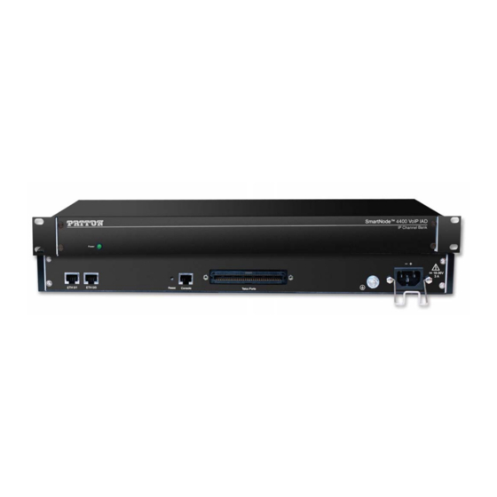
SmartNode 4400 Series detailed description The SmartNode 4400 Series IpChannel Bank provides VoIP calling from 12 to 32 analog phone lines. Inte- grated within the IpChannel Bank are 2 Ethernet ports, one for LAN, the other for WAN connectivity. The front panel contains LED indicators for system status-at-a-glance, and the rear panel provides connectivity for the FXS analog ports, the ENET ports, a WAN port, and an RS-232 control port. -
Page 17: Smartnode 4400 Series Front Panel
SmartNode 4400 Series Getting Started Guide 1 • General information SmartNode 4400 Series front panel The front panel LEDs display the status of the power, system, VOIP channels, Ethernet ports, and call load. The front panel includes the following LEDs. -
Page 18: Smartnode 4400 Series Rear Panels
SmartNode 4400 Series Getting Started Guide SmartNode 4400 Series rear panels The SmartNode 4400 rear panel ports are shown in ETH 0/1 ETH 0/1 ETH 0/0 ETH 0/0 ETH 0/1 ETH 0/1 ETH 0/0 ETH 0/0 Port ETH 0/0 (WAN Ethernet 0/0 port) 10/100Base-Tx full-/half-duplex, RJ-45, auto detection and auto-... -
Page 19: Reset Button Behavior
SmartNode 4400 Series Getting Started Guide Reset button behavior For those SmartNode devices that have a Reset button on the rear panel, its behavior is as follows: • To restart the unit with the current startup configuration—Press for less than 1 second and release the Reset button. -
Page 20: Applications Overview
Chapter 2 Applications overview Chapter contents Introduction ...21 SmartNode 4400 Series applications...21 Enterprise FXS concentration and extension over IP and T1/E1 Bulk analog line extensions Legacy MTU/MDU migration to VoIP based networks ...22 ...22 ...21... -
Page 21: Introduction
The following sections show two typical converged voice-and-data applications. Like all members of the SmartNode family of VoIP solutions, the SmartNode 4400 Series supports all indus- try-standard VoIP signaling protocols, including SIP, H.323, T.38 fax-relay, plus fax- and modem-bypass. The... -
Page 22: Bulk Analog Line Extensions
SmartNode 4400 Series Getting Started Guide 2 • Applications overview Bulk analog line extensions The SN4400 FXS models used in combination enable enterprises to extend up to 32 analog phone lines over any IP link – be it the public Internet, a leased line or a WiMax link. 600kBit/s bandwidth are enough for 32 simulta- neous voice or fax conversations, using G.723 compressed voice transmission. -
Page 23: Hardware Installation
Connecting cables ...28 Connecting the FXS ports Connecting the Ethernet ports Connecting the 10/100Base-T Ethernet ports to an Ethernet switch or Connecting a 10/100Base-T Ethernet port to an Ethernet-capable workstation Connecting the EIA-561 RS-232 configuration port (DCE configured) Connecting power ...30... -
Page 24: Introduction
SmartNode 4400 Series Getting Started Guide Introduction This chapter contains information for planning the installation of the SmartNode 4400 IpChannel Bank with the following installation procedures: • Section “Unpacking the Model SN4400 series IpChannel Bank” ping box • Section “IpChannel Bank chassis installation”... -
Page 25: Installation Checklist
The installation checklist (see table Make a copy of this checklist and mark the entries as you complete each task. For each SmartNode 4400, include a copy of the completed checklist in your site log. This installation checklist is also available in appen- dix F, “Installation checklist”... -
Page 26: Network Information
Draw a network overview diagram that displays all neighboring IP nodes, connected elements and telephony components. IP related information Before you can set up the basic IP connectivity for your SmartNode 4400 series you should have the following information (see table •... -
Page 27: Location And Mounting Requirements
Location and mounting requirements The SmartNode 4400 is intended to be placed on a desktop or similar sturdy, flat surface that offers easy access to the cables or be installed in a standard 19-inch rack chassis. Allow sufficient space at the rear of the chassis for cable connections. -
Page 28: Connecting Cables
SmartNode 4400 Series Getting Started Guide 2. If you are installing the IpChannel Bank in a 19-inch rack, go to step 4. Otherwise, place the IpChannel Bank at the desired location. 3. Go to section “Connecting cables” 4. Install the rack mounting ears onto the IpChannel Bank using the mounting hardware provided. -
Page 29: Connecting The 10/100Base-T Ethernet Ports To An Ethernet Switch Or Hub
Connecting the 10/100Base-T Ethernet ports to an Ethernet switch or hub. The 10/100Base-T Ethernet port is designed to connect to an Ethernet switch or hub with a straight-through or cross-over Ethernet cable. The Ethernet RJ-45 pin and signal definitions for the SN4400 or for a NIC card in a workstation/PC are... -
Page 30: Connecting The Eia-561 Rs-232 Configuration Port (Dce Configured)
SmartNode 4400 Series Getting Started Guide Connecting the EIA-561 RS-232 configuration port (DCE configured) Install the supplied RJ-45-to-RJ-45 cable with the DB9-RJ45 adapter between the SN4400 IpChannel Bank RS-232 console port (figure 10) and an open serial port on your computer. If you need to assemble your own... -
Page 31: Installing The Power Cables-Ac Units
SmartNode 4400 Series Getting Started Guide Figure 11. IEC-320 connector and grounding stud locations 2. Install the grounding wire between the grounding stud (see Mains Voltage: Do not open the case the when the power cord is attached. Line voltages are present within the power supply when the power cords are connected. -
Page 32: Installing The Power Cables-Dc Units
10 feet (3 meters) of the device, shall be easily accessible, and pro- tected by a circuit breaker. Installing the IpChannel Bank Power cable retainer clip Grounding stud on page 44 to find out how to replace it with “Getting started with the SmartNode 4400 Series” 3 • Hardware installation... -
Page 33: Dc Connector, -Dc And +Dc Input View
6. Verify that the green POWER LED is lit. Hardware installation is complete. Refer to chapter 4, page 34. Installing the IpChannel Bank 3 • Hardware installation figure - DC input + DC input Grounding stud “Getting started with the SmartNode 4400 Series” 13). -
Page 34: Getting Started With The Smartnode 4400 Series
Chapter 4 Getting started with the SmartNode 4400 Series Chapter contents Introduction ...35 1. Configure IP address ...36 Factory-default IP settings Connect to the RS-232 console port Login ...38 Changing the WAN IP address 2. Connecting the SmartNode to the network 3. -
Page 35: Introduction
2. Connecting the SmartNode to the network (see page 36 for details). PC or workstation or Telnet Figure 15. Connecting the SmartNode to the network Introduction 4 • Getting started with the SmartNode 4400 Series on page 23. figure 14). Refer to section rt s lc o... -
Page 36: Configure Ip Address
39. Otherwise, refer to the following sections to change the addresses and network masks. 1. Configure IP address 4 • Getting started with the SmartNode 4400 Series figure 16). Refer to section “2. Connecting the SmartNode to the net- Figure 16. -
Page 37: Connect To The Rs-232 Console Port
No parity • 8 bit • 1 stop bit • No flow control 1. Configure IP address 4 • Getting started with the SmartNode 4400 Series 0 -2 0 -6 rt s lc o o le Console port 0 /0... -
Page 38: Login
172.16.1.99(if-ip)[eth0]#copy running-config startup-config 172.16.1.99(if-ip)[eth0]# The SmartNode can now be connected to your network. 1. Configure IP address 4 • Getting started with the SmartNode 4400 Series and leave the password empty. Press the <Enter> key after the... -
Page 39: Connecting The Smartnode To The Network
In general, the SmartNode will connect to the network via the ETH 0/0 (WAN) port. This enables the SmartNode to offer routing services to the PC hosts on the ETH 0/1 (LAN) port. The SmartNode 4400 Series is equipped with Auto-MDI-X Ethernet ports, so you can use straight-through or crossover cables for host or... -
Page 40: Bootloader
SmartNode via one of the Ethernet interfaces, or open a CLI session via the console port (if available on the SmartNode). The following prompt will be displayed: RedBoot> Type help to display an overview of the available commands. Bootloader 4 • Getting started with the SmartNode 4400 Series... -
Page 41: Start-Up With Factory Configuration
RedBoot> fis delete -n 1 RedBoot> fis create RedBoot> fis list -l Bootloader 4 • Getting started with the SmartNode 4400 Series Purpose Copies the SmartWare application image from the persistent memory (flash:) to the volatile memory (RAM) from where it will be executed. - Page 42 1693438 0x01800100 0x01800100 RedBoot> go Starting 'SmartWare R2.10 BUILD28015' at 0x01800100 via 0x01800100 Bootloader 4 • Getting started with the SmartNode 4400 Series Starts the application image that was down- loaded into the volatile memory (RAM). State Description Version valid SmartWare R2.10 BUILD28015...
-
Page 43: Load A New Application Image (Smartware) Via The Serial Link
On the CD you will also find a freeware TFTP server, which is also available from the www.solarwinds.net web site. Additional information 4 • Getting started with the SmartNode 4400 Series Purpose Downloads an application image into the volatile memory (RAM) from where the SmartNode could directly execute it. -
Page 44: Contacting Patton For Assistance
Chapter 5 Contacting Patton for assistance Chapter contents Introduction ...45 Contact information...45 Warranty Service and Returned Merchandise Authorizations Warranty coverage ...45 Out-of-warranty service Returns for credit ...46 Return for credit policy RMA numbers ...46 Shipping instructions (RMAs)...45 ...46 ...46 ...46... -
Page 45: Introduction
SmartNode 4400 Series Getting Started Guide Introduction This chapter contains the following information: • “Contact information”—describes how to contact Patton technical support for assistance. • “Warranty Service and Returned Merchandise Authorizations SmartNode warranty and obtaining a return merchandise authorization (RMA). -
Page 46: Out-Of-Warranty Service
SmartNode 4400 Series Getting Started Guide Out-of-warranty service Patton services what we sell, no matter how you acquired it, including malfunctioning products that are no longer under warranty. Our products have a flat fee for repairs. Units damaged by lightning or other catastro- phes may require replacement. -
Page 47: A Compliance Information
Appendix A Compliance information Chapter contents Compliance ...48 EMC compliance: ...48 Safety compliance: ...48 CE Declaration of Conformity Authorized European Representative ...48 ...48... -
Page 48: A Compliance Information
SmartNode 4400 Series Getting Started Guide Compliance EMC compliance: • FCC Part 15, Class A • EN55022, Class A • EN55024 • EN-61000-3-2 Harmonics • EN-61000-3-3 Flicker • EN-61000-4-2 ESD • EN-61000-4-3 Radiated Immunity • EN-61000-4-4 EFT • EN-61000-4-5 Surge •... -
Page 49: Specifications
Appendix B Specifications Chapter contents Voice connectivity - FXS ...50 Ethernet interface ...50 Console port...50 FXS ports ...50 PPP and Frame-Relay support Voice processing (signaling dependent) Fax and modem support...51 Voice signaling ...51 Voice routing-session router ...52 services...52 Management ...52 Operating environment ...52 Temperature... -
Page 50: B Specifications
SmartNode 4400 Getting Started Guide Voice connectivity - FXS 2-wire Loopstart, RJ-11/12 Short haul loop 1.1 km @3REN EuroPOTS (ETSI EG201 188) Programmable AC impedance, feeding, and ring voltage; on-hook voltage 48 VDC Caller-ID Type-1/2 FSK and ITU V.23/Bell 202 generation... -
Page 51: Fax And Modem Support
SmartNode 4400 Getting Started Guide • G.729ab (8 kbps) • Transparent pass through • G.168 echo cancellation • Up to 32 parallel voice connections • DTMF detection and generation • Carrier tone detection and generation • Silence suppression and comfort noise •... -
Page 52: Voice Routing-Session Router
SmartNode 4400 Getting Started Guide Voice routing-session router Local switching; Interface huntgroups Routing Criteria: • Interface • Calling/called party number • Time of day, day of week, date Number manipulation functions: • Replace numbers; Add/remove digits • Multiple remote gateways; PLAR IP services IPv4 router;... -
Page 53: Altitude
SmartNode 4400 Getting Started Guide Altitude Maximum operating altitude: 15,000 feet (4,752 meters) System • The processor is a Motorola MPC875 series 32-bit PowerPC core, 133 MHz • 8 MB Flash • 32 MB SDRAM Dimensions 1.75 inches (4.44 cm) height, standard 19-inch (48.26 cm) width, 12 inches (30.48 cm) depth... -
Page 54: Identification Of The Smartnode Devices Via Snmp
SmartNode 4400 Getting Started Guide Identification of the SmartNode devices via SNMP All SmartNode devices have assigned sysObjectID (.iso.org.dod.internet.mgmt.mib-2.system.sysObjectID) numbers (see table Table 9. SmartNode Models and their Unique sysObjectID SmartNode Model SN4408/JS/RUI SN4412/JS/RUI SN4416/JS/RUI SN4424/JS/RUI SN4432/JS/RUI According to table 9, an SNMP get request to .iso.org.dod.internet.mgmt.mib-2.system.sysObjectID of a Smart-... -
Page 55: Port Pin-Outs
Appendix C Port pin-outs Chapter contents Introduction ...56 Console port...56 Ethernet 10Base-T and 100Base-T port FXS ports ...57 ...56... -
Page 56: C Port Pin-Outs
SmartNode 4400 Series Getting Started Guide Introduction This section provides pin-out information for the ports of the SmartNode. Console port Configuration settings: Asynchronous data rate of 9600 bps, 2 bits, no parity, 1 stop bit, no flow control Note Pins not listed are not used. -
Page 57: Fxs Ports
SmartNode 4400 Series Getting Started Guide FXS ports The FXS ports are accessed through a 64-pin RJ-21X connector (see RJ-21X connector (see table 11 on page 59 for pin-outs) located on the rear panel of the IpChannel Bank. Table 10. Band marked color-codes for the 64-pin RJ-21X connector... - Page 58 SmartNode 4400 Series Getting Started Guide Table 10. Band marked color-codes for the 64-pin RJ-21X connector (Continued) Wire/Color Code Main color Stripe Yellow Orange Orange Yellow Yellow Green Green Yellow Yellow Brown Brown Yellow Yellow Slate Slate Yellow Purple Blue...
-
Page 59: Band Marked Color-Codes For The 50-Pin Rj-21X Connector
SmartNode 4400 Series Getting Started Guide Table 11. Band marked color-codes for the 50-pin RJ-21X connector Wire/Color Code Main color White Blue White Orange White Green White Brown White Slate Blue Orange Green Brown Slate Black Blue Black Orange Black... - Page 60 SmartNode 4400 Series Getting Started Guide Table 11. Band marked color-codes for the 50-pin RJ-21X connector (Continued) Wire/Color Code Main color Yellow Brown Yellow Slate Violet Blue Violet Orange Violet Green Violet Brown Violet Slate FXS ports Tip & Ring...
-
Page 61: D Factory Configuration
Appendix D Factory Configuration Chapter contents Introduction ...62... -
Page 62: Introduction
SmartNode 4400 Getting Started Guide Introduction The factory configuration settings for SmartNode 4400 Series devices are as follows: #----------------------------------------------------------------# # 4400 Series # Factory configuration file #----------------------------------------------------------------# dns-relay sntp-client sntp-client server primary 129.132.2.21 port 123 version 4 system ic voice 0... -
Page 63: End User License Agreement
Appendix E End user license agreement Chapter contents End User License Agreement ...64 1. Definitions ...64 2. Title ...64 3. Term ...64 4. Grant of License ...64 5. Warranty ...64 6. Termination ...65 7. Other licenses ...65... -
Page 64: End User License Agreement
SmartNode 4400 Getting Started Guide End User License Agreement By opening this package, operating the Designated Equipment or downloading the Program(s) electronically, the End User agrees to the following conditions: 1. Definitions Effective Date shall mean the earliest date of purchase or download of a product containing the Patton Electronics Company Program(s) or the Program(s) themselves. -
Page 65: Termination
SmartNode 4400 Getting Started Guide If the Program(s) are acquired by or on behalf of a unit or agency of the United States Government, the Gov- ernment agrees that such Program(s) are commercial computer software or computer software documentation and that, absent a written agreement to the contrary, the Government’s rights with respect to such Program(s) are... -
Page 66: Installation Checklist
Appendix F Installation checklist Chapter contents Introduction ...67... -
Page 67: Introduction
SmartNode 4400 Series Getting Started Guide F • Installation checklist Introduction This appendix lists the tasks for installing a SmartNode 4400 IpChannel Bank (see table 12). Make a copy of this checklist and mark the entries as you complete each task. For each IpChannel Bank, include a copy of the completed checklist in your site log. -
Page 68: Accessories
Appendix G Accessories Chapter contents Introduction ...69... -
Page 69: Introduction
SmartNode 4400 Getting Started Guide Introduction The cables listed in table 13 are available as accessories for the SmartNode 4400 Series products. Description 64-pin telco to open end cable, 6 ft/1.8 m (64-pin FSX port) 50-pin telco to open end cable, 20 ft/6 m 50-pin telco/16 ends RJ-11 cable, 6 ft/1.8 m...