Table of Contents
Advertisement
Quick Links
Advertisement
Table of Contents

Related Manuals for Patton electronics 2715


Summary of Contents for Patton electronics 2715
- Page 1 USER MANUAL MODEL 2715 NetLink-E1: E1/Fractional E1 NTU Part# 07M2715-UM SALES OFFICE Doc# 08605U2-001, (301) 975-1000 Rev. C TECHNICAL SUPPORT Revised 10/26/06 C E R T I F I E D (301) 975-1007 An ISO-9001 http://www.patton.com Certified Company...
-
Page 2: Table Of Contents
2.2 General Product Description is limited to defects in workmanship or materials, and does not cover 2.3.1 The 2715 as the Interface between the Telco and CPE customer damage, abuse, or unauthorized modification. This product 2.3.2 The 2715 as a High-Speed Short Range Modem contains no serviceable parts;... -
Page 3: Radio And Tv Interference
(301) 975-1007; commercial installation. However, there is no guarantee that interference email: support@patton.com will not occur in a particular installation. If the Model 2715 does cause www: http://www.patton.com. interference to radio or television reception, which can be determined by disconnecting the cables, the user is encouraged to try to correct... -
Page 4: Features
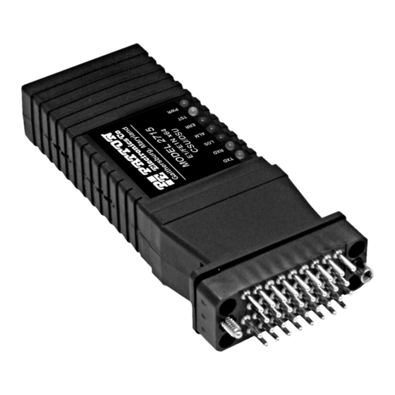
2.048 Mbps G.703 E1 (clear channel) and fractional E1 G.704 (n x 64) 4-wire circuit. housed in our MicroPak enclosure measuring only 9 x 5.3 x 2 cm (3.55 x 2.1 x 0.78 in.) the Model 2715 plugs directly Model 2715 Model 2715 into the V.35 DTE interface of a router, switvh, FRAD, multiplexer or... -
Page 5: Dip Switch Configuration
Figure 1. Model 2715 bottom view, showing location of DIP switches Line Coding Options: The Model 2715 DIP switches (Switches SW1 - SW8) can be con- High Density Bipolar 3 (HDB3): In HDB3 coding, the transmitter figured as either “On” or “Off”. Figure 2 (below) shows the orientation deliberately inserts a bipolar violation when excessive zeros of the DIP switches with respect to ON/OFF positions. - Page 6 In unframed mode, SW3 is used to along with SW4 to determine the 192kbps clock mode. In unframed mode, the model 2715 can be set to network, 256kbps internal or external clock mode. This is done by setting both SW3 and 384kbps SW4 to the on position.
- Page 7 DSR/DTR hardware flow control: O f f allows you to monitor/configure its operating parameters. Follow the instructions below to configure the Model 2715 using the software switches: When the unit is first turned on, the terminal screen may appear blank. Press the [Enter] key. If your serial connection...
-
Page 8: Introduction To Main Menu
Unit Options allow you to customize the Model 2715 for your location. You can change the default header names to give each unit a unique name and password. Also, you can reset the unit to its default settings without the manual. - Page 9 Line Coding: HDB3 (default) 3.2.2 System Configuration Options: AMI, HDB3 The System Configuration menu looks like this: HDB3: In this line coding, the transmitter substitutes a deliberate bipolar violation when excessive zeros in the data stream are detected. The receiver recognizes these special violations and decodes them as zeros.
- Page 10 4 MF; otherwise, the one using CRC-4 MF will detect a loss of sync. Options: EEPROM, Switch The Model 2715 can be initialized via the configuration in the on-board permanent memory (EEPROM) or via the internal DIP switches (Switch). Once the unit is powered up, you may change the settings through the control port or the DIP switches.
- Page 11 The Local Loop is a bi-lateral loopback in which the data from the local DTE and the data from the remote unit are looped back to their respec- You may configure the Model 2715 to operate with any combination of tive sources (See Section 5.3). Activate this loop to test the each of active and inactive DS0 channels in this screen.
- Page 12 Remote Loop Idle (default) The Model 2715 receiving a RL can be in one of the following states: The Remote Digital Loopback (RDL) test checks the performance RxPr The Model 2715 is receiving a preparatory pattern. of both the local and remote Model 2715s, as well as the communica- tion link between them.
- Page 13 Use this option to select the test pattern used to test the link. 3.2.4 Unit Options NI STATUS The Unit Options screen looks like this (factory default): The Network interface (NI) status is shown in the middle of the Diagnostics/Statistics screen.
-
Page 14: Dte Interface Connection
Signal Name Set to Default Configuration (RX) Receive (Ring) (RX) Receive (Tip) You may set the Model 2715 to its factory default configuration, except Shield for the header lines and the password, by executing the Set to Default (TX) Transmit (Ring) Configuration command. -
Page 15: Power Connection
IEC-320 power entry connector. This power sup- of the LEDs on the Model 2715 front panel. ply connects to the Model 2715 by means of a barrel jack on the rear panel. There are a variety of international power cords available for the universal power supply. -
Page 16: Loop (V.54 & Telco) Diagnostics
Model 2715, and is performed separately on each unit. Any data sent Alarms may occur due to: to the local Model 2715 in this test mode will be echoed (returned) back to the user device (i.e., characters typed on the keyboard of a ter- •... -
Page 17: Bit Error Rate (V.52) Diagnostics
Diagnostics/Statistics menu and toggle the <Spacebar> until “TM” appears next to the Remote Loop option.; When a 511, 2047, or QRSS test is invoked, the Model 2715 gen- erates a pseudo-random bit pattern of 511 bits, 2047 bits or 2 bits, Activate the “RL”... - Page 18 Line Framing: G.703 (Unframed) or G.704/G.732 (Framed) CAS Multiframing: Selectable On or Off To gain optimum performance from the Model 2715 , please keep CRC-4 Multiframing: Selectable On or Off the following guidelines in mind: Clocking: Internal, External, or Receive Recover •...
- Page 19 INTERFACE PIN ASSIGNMENTS AND ACCESSORIES RJ-48C E1 Network Interface Patton Model # Description (RJ-48S Female Modular Jack) 2715/CM/UI .....V.35 to E1 Converter (V.35 M/34 Male, Pin # Signal 10 - 09F......6 Foot Control Port Cable, 25 mm to RX Data (RING) DB9F...
- Page 20 TC/ (Transmitter Clock -, DCE Source) Aux. Power Input (+5VDC @ 300mA) NOTE: Model 2715 is factory configured to accept power from the enclosed DC wall adapter (See Sections 4.3.1 and 4.3.2 above). If you wish to supply power via pin KK on the interface, you must change the setting of the power supply jumper on the printed circuit board.
- Page 21 Copyright © 2006 Patton Electronics Company All Rights Reserved.
Need help?
Do you have a question about the 2715 and is the answer not in the manual?
Questions and answers