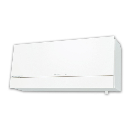
Mitsubishi Electric vl-100u5-e Installation Manual
Lossnay ventilator
Hide thumbs
Also See for vl-100u5-e:
- Handbook (24 pages) ,
- Operating instructions manual (16 pages) ,
- Operating instructions manual (13 pages)
Subscribe to Our Youtube Channel
Summary of Contents for Mitsubishi Electric vl-100u5-e
- Page 1 1305875HF7701 Mitsubishi Lossnay Ventilator MODEL: VL-100U (pull cord Type) VL-100EU (wall switch Type) Installation Manual...
-
Page 2: Table Of Contents
Mitsubishi Lossnay Ventilator MODEL: VL-100U (pull cord type) VL-100EU (wall switch type) Installation Manual For Dealer and Contractor Please ensure that the separate “Operating Instructions” Contents Page are handed over to the customer. Please ensure that it is Safety precautions ......1 delivered to the customer. -
Page 3: Dimensional Outline Drawing
- Electrical work must be done by - Attach the unit so that the air an electrical contractor (a licensed supply/exhaust pipes slope electrician) in accordance with downward toward outdoors. - Rainwater entering the unit could the technical standards of the equipment and local regulations result in electric shock, fire or indoor to ensure safety. -
Page 4: List Of Included Parts
■ Mounting position diagram (seen from inside) Edge of main unit Mounting hole 36 – ø6 Require to be secured Mounting plate Air exhaust hole (ø85 to ø90 wall hole) Power and connection cable pullout area (VL-100EU -E only) (min.) (Adjustable) (Adjustable) (max.) Air intake hole (ø85 to ø90 wall hole) (min.) (min.) Unit (mm) List of included parts... -
Page 5: Mounting Instructions
Mounting instructions Wall-hole construction 3. Drill the wall holes. 1) Remove the loosely fastened mounting plate. 1. Determine the installation position. (Leave the wood screw loosely fastened in 1) Make sure to allow the required clearances (at procedure 1 in place.) least 64 mm on top, 83 mm to left and right, 2) Drill the wall holes of ø85 to ø90 mm. and 113 mm on bottom) around the mounting Wall plate, as shown in the drawing below. Wood screw (fasten loosely) Diameter of wall hole 5° ø85 to ø90 mm Wall hole At least Inside Outside 64 mm... -
Page 6: Cutting Air Supply/Exhaust Pipes
Cutting air supply/exhaust pipes Note - Check that each air supply/exhaust pipe 1) Measure the wall thickness. A catches on all four prongs of its pipe (If the wall is more than 300 mm thick, use mounting plate. (If a prong has not caught, the provided air supply/exhaust pipe B). (See the pipe will press against the back of page 4, section 4, for mounting instructions.) the Lossnay unit and the shutter may not Cut on this side... -
Page 7: Attaching Air Supply/Exhaust Pipes
Attaching air supply/exhaust pipes Attaching the main unit 1) Insert the air supply/exhaust pipes, which are For VL-100U attached to the pipe mounting plates, into the 1) Hang the catch holes on the main unit onto wall holes. the catches of the mounting plate as shown 2) Tape the air supply/exhaust pipes tightly to below. (Both sides) the wall as shown below using off-the-shelf 2) Press the main unit into the wall and secure aluminum tape. (If the seal is not tight, the it with the two screws provided. At this time, pipes may shift and the shutter may not firmly press the power cord into the cut-out on operate properly.) - Page 8 Note Operation requires a control switch. Have a control switch ready and - Be sure not to misplace the removed terminal block covers and screw. connect the wiring shown in bold on the connection diagram below. 4) Pull the power and connection cables through the hole in the rear of the unit. (The cables Suitable cables: ø0.5 to ø2.0 mm diameter enter the room at the power/connection cable...
-
Page 9: Outdoor Construction
Outdoor construction 3. Preventing infiltration of rainwater Caulk around the entire perimeter of the weather 1. Fill the wall hole. covers. Fill in any gaps between the air supply/exhaust Caulking pipes and the wall holes with off-the-shelf caulking. Caulking Weather covers Air supply/exhaust pipes Note - Any spaces left unfilled will allow rainwater to enter. 2. Installing the weather covers 1) Insert the weather cover mounting plates into the air supply/exhaust pipes. -
Page 10: Checks After Mounting
Checks after mounting ■ After mounting is complete, check the checklist items before doing a test run. ■ Be sure to correct any problems discovered.(Failure to do so will not only prevent features from operating, it will also imperil your safety.) ■ Checklist Check items Remedy for problem Checked? Is the main unit mounting strong Reinforce it. enough? Is the main unit attached securely? Tighten the mounting screws. Installation Is the panel securely closed? Close the panel. Did you caulk? (The air supply/ Caulk. exhaust pipe should be caulked (Failure to caulk will allow rainwater outside, as should the outdoor hood.) infiltration.)


Need help?
Do you have a question about the vl-100u5-e and is the answer not in the manual?
Questions and answers