Mitsubishi Electric VL-350CZPVU-L-E Installation Manual
Lossnay heat recovery ventilator (residential use)
Hide thumbs
Also See for VL-350CZPVU-L-E:
- Handbook (166 pages) ,
- Installation manual (48 pages) ,
- Instruction manual (21 pages)
Table of Contents
Advertisement
Quick Links
LOSSNAY HEAT RECOVERY VENTILATOR (RESIDENTIAL USE)
MODEL
VL-250CZPVU-R-E, VL-250CZPVU-L-E
VL-350CZPVU-R-E, VL-350CZPVU-L-E
VL-500CZPVU-R-E, VL-500CZPVU-L-E
Installation Manual
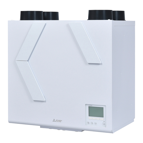
* The figure shows VL-350CZPVU-R-E
■ This product is for residential use.
■ This product must be correctly installed to ensure that its performance and functions are properly demonstrated
and to ensure its safe use and operation. Before installation, please read this installation manual thoroughly.
Before using exclusive system components, read the installation manual for the system components thoroughly.
■ For installation parts, be sure to use accessories and designated parts. Use of non-designated parts may be a
cause of malfunction.
■ Installation must be performed by dealers and electrical contractors. Incorrect installation by the customer may be
a cause of equipment malfunction or an accident.
■ Electrical work must be performed by a properly qualified electrician of the dealer or electrical contractor.
■ Please note that enough working space (remove the cover, replace the filter, etc.) is required around the product
for maintenance.
■ Install the product indoor.
For dealer/contractor
Contents
1. Safety Precautions �������������� 2
2. Outside Dimensions ������������� 6
3. Standard Installation Example �������� 12
3.1 Installation example ����������� 12
3.2 Working space ������������� 13
4. Installation Procedure ����������� 16
4.1 Wall bracket �������������� 16
4.2 Mounting the Product ���������� 16
4.3 Fixing the Product ������������ 16
4.4 Connecting the Pipes ���������� 17
4.5 Drain piping ��������������� 19
5. Electrical Work ��������������� 20
5.1 Standard use �������������� 20
5.2 External device connection use ������ 21
■ Post-installation Checks ����������� 26
6. How to use Controller ������������ 27
6.1 Controller button functions �������� 27
6.2 Menu structure ������������� 28
6.4 Commissioning menu ���������� 29
6.5 Function setting ������������� 45
6.6 Error list ���������������� 48
6.7 Trial operation � ������������� 48
7. Explaining to the User ������������ 50
Eng-1
2103876H46502
Advertisement
Table of Contents

Related Manuals for Mitsubishi Electric VL-350CZPVU-L-E


Summary of Contents for Mitsubishi Electric VL-350CZPVU-L-E
-
Page 1: Table Of Contents
2103876H46502 LOSSNAY HEAT RECOVERY VENTILATOR (RESIDENTIAL USE) MODEL VL-250CZPVU-R-E, VL-250CZPVU-L-E VL-350CZPVU-R-E, VL-350CZPVU-L-E VL-500CZPVU-R-E, VL-500CZPVU-L-E Installation Manual For dealer/contractor Contents 1. Safety Precautions �������������� 2 2. Outside Dimensions ������������� 6 3. Standard Installation Example �������� 12 3.1 Installation example ����������� 12 3.2 Working space ������������� 13 4. Installation Procedure ����������� 16 4.1 Wall bracket �������������� 16 4.2 Mounting the Product ����������... -
Page 2: Safety Precautions
1. Safety Precautions The following symbols indicate the degree of danger caused Symbols used in the text and on the main unit have the by incorrect handling of the product. following meanings. Do not install in WARNING CAUTION Prohibited bathroom Incorrect handling of the Incorrect handling may result Do not disassemble Be sure to ground product may result in serious in minor injury or physical injury or death. damage to the house or Do not wet Follow instructions household goods. WARNING Do not install the product in hot places, in the direct sunlight and in smoky places. Failure to heed this warning may result in fire. - Page 3 WARNING For installation work parts, make sure to use only accessories and designated parts Use of non-designated parts may result in equipment damage or accidents. When using duct heaters (supply air preheaters, supply air after-heaters), make sure to use safety devices that do not have self-return functions. Do not supply the duct heaters with electricity directly from the product. Failure to heed this warning may result in fire.
- Page 4 CAUTION Do not install the product at regions or locations that exceed the following operating conditions. If these operating conditions are exceeded, dew condensation water might drip. Outdoor air temperature: -15 to 40 ºC Area around the product and ambient temperature and humidity:0 to 40 ºC 80%RH or less and at absolute humidity or less where the dew point temperature of 12 ºC (20 ºC 60%RH or equivalent) is reached under the above minimum outdoor air temperature conditions Do not install the product at locations where the product is prone to be damaged from salt or hot springs. Failure to heed this warning may result in malfunction of product.
- Page 5 Note - Do not install the product at locations where toxic gas or gas containing corrosive components such as acids, alkaline, organic solvents, or paints is generated. (Failure to heed this warning may result in malfunction.) Do not install the product near bedrooms. (Failure to heed this warning may cause complaints about noise.) - For living rooms (for example, bed rooms) where it is anticipated that building ambient noise will be below 30 dB(A), use commercially available ducts that have sound deadening qualities on the supply air side. (Sound from the product resonatesin inside the ducts and may result abnormal noise being emitted from the air vent.) - Install supply air and exhaust air grills at locations where they are less likely to reverberate. (Failure to heed this warning may cause complaints about noise.) - In cold regions or regions with strong winds, wind outside sometimes gets inside when operation of the product is stopped. So, we recommend providing a motorized shutter midway along the supply air and exhaust air ducts. - Install the product so that discharged gas or exhaust air from burning appliances and equipment does not flow back inside the product. - At the outdoor hood installation position, allow at least 3x the diameter of the duct through holes between the outdoor hood and the ducts so that exhaust air is not mixed in with supply air. (Preferably a distance of 450 mm or more should be ensured between the outdoor hood and the ducts.) - Do not connect duct pipes in the ways shown below. (Failure to heed this warning may cause the air flow to decrease or result in abnormal noise.) - Extremely sharp bends - Many bends - Bending right next to the - Extreme narrowing of the duct connection flange duct diameter - Use an exhaust air filter that has a non-woven fabric type filter. - To reduce the noise of drain discharge, make sure to connect commercially available check valves to the drain piping. Use check valves in line with their instructions. - Make the opening at the end of the drain piping face down so that water drains well. - Make sure to install a drain pipe independently. (When you connect common drainage pipe of an apartment house,it may cause backflow of drain.) - The duct from the outdoor hood should have an uphill slope of 1/30 or more. (It may cause rainwater to enter the inside of duct.)
-
Page 6: Outside Dimensions
2. Outside Dimensions ■VL-250CZPVU-R-E Pipe guide (EA) RA: Return Air SA: Supply Air EA: Exhaust Air Pipe guide (RA) OA: Outdoor Air Pipe guide (SA) Pipe guide (OA) Wall bracket (accessory) Wall mount hook top φ122 Filter cover (OA) Filter cover (RA) Heat exchanger Filter cover (SA) Wall mount hook down Wall mount hook center Controller Cable strap hole Power supply cord Control box Drain pipe (SA) Drain pipe (EA) Unit (mm) φ22 φ22 Accessories Wall bracket: 1 Slim-Lossnay Drain hose fixture: 2 Washer: 8 Drain hose: 1 Cable strap: 1 connection cable: 1 (250 mm) (100 mm) Eng-6... - Page 7 ■VL-250CZPVU-L-E Pipe guide (SA) RA: Return Air SA: Supply Air EA: Exhaust Air Pipe guide (OA) OA: Outdoor Air Pipe guide (EA) Pipe guide (RA) Wall mount hook top Wall bracket (accessory) φ122 Filter cover (RA) Filter cover (OA) Heat exchanger Controller Wall mount hook down Wall mount hook center Filter cover (SA) Drain pipe (EA) Drain pipe (SA) φ22 φ22 Power supply cord Control box Unit (mm) Cable strap hole Accessories Wall bracket: 1 Slim-Lossnay Drain hose fixture: 2 Washer: 8 Drain hose: 1 Cable strap: 1 connection cable: 1 (250 mm) (100 mm) Eng-7...
- Page 8 ■VL-350CZPVU-R-E Pipe guide (EA) RA: Return Air SA: Supply Air EA: Exhaust Air Pipe guide (RA) OA: Outdoor Air Pipe guide (SA) Pipe guide (OA) Wall bracket (accessory) Filter cover (OA) Wall mount hook top φ145 Filter cover (RA) Heat exchanger Filter cover (SA) Controller Wall mount hook center Wall mount hook down Cable strap hole Power supply cord Control box Drain pipe (SA) Drain pipe (EA) Unit (mm) φ22 φ22 Accessories Wall bracket: 1 Slim-Lossnay Drain hose fixture: 2 Washer: 8 Drain hose: 1 Cable strap: 1 connection cable: 1 (250 mm) (100 mm) Eng-8...
- Page 9 ■VL-350CZPVU-L-E Pipe guide (SA) RA: Return Air SA: Supply Air EA: Exhaust Air Pipe guide (OA) OA: Outdoor Air Pipe guide (EA) Pipe guide (RA) Wall bracket Wall mount hook top Filter cover (RA) (accessory) φ145 Filter cover (OA) Heat exchanger Controller Wall mount hook down Wall mount hook center Filter cover (SA) Drain pipe (EA) Drain pipe (SA) φ22 φ22 Control box Power supply cord Cable strap hole Unit (mm) Accessories Wall bracket: 1 Slim-Lossnay Drain hose fixture: 2 Washer: 8 Drain hose: 1 Cable strap: 1 connection cable: 1 (250 mm) (100 mm) Eng-9...
- Page 10 ■VL-500CZPVU-R-E Pipe guide (EA) RA: Return Air SA: Supply Air EA: Exhaust Air Pipe guide (RA) OA: Outdoor Air Pipe guide (SA) Pipe guide (OA) Wall bracket (accessory) Filter cover (OA) φ183 Wall mount hook top φ157 Filter cover (RA) Heat exchanger Filter cover (SA) Wall mount hook down Controller Wall mount hook center Cable strap hole Power supply cord Control box Drain pipe (EA) Drain pipe (SA) φ22 φ22 Unit (mm) Accessories Wall bracket: 1 Slim-Lossnay Drain hose fixture: 2 Washer: 8 Drain hose: 1 Cable strap: 1 connection cable: 1 (250 mm) (100 mm) Eng-10...
- Page 11 ■VL-500CZPVU-L-E Pipe guide (SA) RA: Return Air SA: Supply Air EA: Exhaust Air Pipe guide (OA) OA: Outdoor Air Pipe guide (EA) Pipe guide (RA) Wall bracket Wall mount hook top (accessory) Filter cover (RA) φ183 φ157 Filter cover (OA) Heat exchanger Controller Wall mount hook down Filter cover (SA) Wall mount hook center Drain pipe (SA) Drain pipe (EA) φ22 φ22 Power supply cord Control box Cable strap hole Unit (mm) Accessories Wall bracket: 1 Slim-Lossnay Drain hose fixture: 2 Washer: 8 Drain hose: 1 Cable strap: 1 connection cable: 1 (250 mm) (100 mm) Eng-11...
-
Page 12: Standard Installation Example
3. Standard Installation Example 3.1 Installation example Note - Make sure that the exhaust air connection has two or more confluence points with the piping from the bathroom. - Preheaters and electric dampers may be required in your region. - Read the instructions carefully in advance when using optional components and commercially available components. sensor (Field supply) Living room... -
Page 13: Working Space
3.2 Working space (required space around the product) This product requires regular maintenance (filter cleaning, parts replacement). Place the product away from any other obstacles for maintenance. ■VL-250CZPVU-R-E Control box Space to pull out Unit (mm) ■VL-250CZPVU-L-E Control box Space to pull out Unit (mm) Note - Secure about 2 mm of clearance from the side faces of the product to any other obstacles. (If not enough clearance is secured, maintenance cannot be performed. - Page 14 ■VL-350CZPVU-R-E Control box Space to pull out Unit (mm) ■VL-350CZPVU-L-E Control box Space to pull out Unit (mm) Note - Secure about 10 mm of clearance from the side faces of the product to any other obstacles. (If not enough clearance is secured, maintenance cannot be performed. Plus, vibration can result.) - Secure space below the product for withdrawing the control box.
- Page 15 ■VL-500CZPVU-R-E Control box Space to pull out Unit (mm) ■VL-500CZPVU-L-E Control box Space to pull out Unit (mm) Note - Secure about 10 mm of clearance from the side faces of the product to any other obstacles. (If not enough clearance is secured, maintenance cannot be performed. Plus, vibration can result.) - Secure space below the product for withdrawing the control box.
-
Page 16: Installation Procedure
4. Installation Procedure 4.2 Mounting the Product WARNING Select a place which is strong enough to support the CAUTION product, and install the product securely. Do not carry with a pipe guide. Injury could result if parts fall. Failure to heed this warning may result in damage to pipe guide. CAUTION Do not place the product directly on the floor. Install the product in the indoor side of the insulation Failure to heed this warning may result in damage to the drain layer/airtight layer. -
Page 17: Connecting The Pipes
1/30 towards the outside. (Product) Failure to heed this warning may cause rain penetration, Caulking material resulting in electric shock/fire or water damage to household (Field supply) property. ■VL-350CZPVU-R-E Piping should be installed so that no load is applied to the pipe guide. ■VL-350CZPVU-L-E Failure to heed this warning may cause damper mulfunction. Aluminum tape Duct Inner diameter (Field supply) φ150 (Field supply) Note - When discharging the air from a bathroom, use ducts made of a material that does not allow water to leak. - When using PVC ducts or metal ducts for the SA side ducts, make sure to connect ducts having silencer before the grill. - Page 18 RA (Return Air) side ducts also. (i.e. not operated for 24 hours). Indoor humidity can cause condensation because exposed parts can become cold in winter. ■VL-250CZPVU-R-E ■VL-250CZPVU-L-E Insulating (Field supply) ■VL-350CZPVU-R-E ■VL-350CZPVU-L-E Insulating (Field supply) ■VL-500CZPVU-R-E ■VL-500CZPVU-L-E Insulating (Field supply) Note - A ttach insulation so that the aluminum tape is not exposed. Eng-18...
-
Page 19: Drain Piping
4.5 Drain piping 4.5.1 Connection method of drain hose (EA drain pipe) CAUTION 1) S ecurely connect the accessary drain hose to the root of the connection port. Make sure to connect drain piping by the following Securely fix the accessory hose band by tightening with procedure to prevent freezing and dew condensation forming on the surface of the piping a flat head screwdriver. (Otherwise, water leakage can - Connect the drain piping on the indoor side of the insulation result.) -
Page 20: Electrical Work
5. Electrical Work 5.1 Standard use WARNING Power cord (product) Electrical work must be carried out safely and reliably by a professional electrical contractor (properly qualified - LS (Black cord) means Live switch for kitchen and bath electrician) in accordance with internal wiring provisions room. When you use LS, remove protective tube. and electricalequipment technical standards. LS (Black): covered by a Poor connection and faulty electrical work could result in protective tube electric shock or fire. -
Page 21: External Device Connection Use
5.2 External device connection use 4) Make a cut in the Bush. Then pass the cord of the external device through the Bush. Connect the each cable for external devices to the control Attach the insulating sheet on the control box. circuit board according to the way below. Insert the control box to the product, attach it with two 1) Remove 2 screws. Pull the control box. (It stops in the screws. (Don't forget to place the insulating sheet) middle) Bind the external device wirings with a cable strap (Included) and attach it under the product. (It is recommended to install it with flexibility so that it will not be loaded from the outside.) Insert the cutting Bush Controll box Controll box Screw 2) Remove an insulating sheet. (Be careful of the protrusions on both sides of the control box) Protrusion Screw Cable strap Insulating sheet Controll box 3) Connect the cables. TM201 TM200 CN105 CN 105: IT interconnection Wi-Fi TM200 1(+,–): Analog input 1 for Sensor 0-10V 2(+,–): Analog input 2 for Sensor 0-10V TM201 1-2: Volt-free contact for bypass switch 3-4: Volt-free contact for boost switch TM2: Slim-Lossnay connection cable TM3: Signal output... - Page 22 5.2.1 Diagram for control circuit board Control circuit board Signal interface circuit board (VL-40S) SW2 (This is used CN105 at trial operation) TM201 TM200 LED1 (This is used at trial operation) 5.2.2 Terminal connection specifications and functions Selection requirement Wiring Setting Terminal Category No Input/Output Terminal rating Diameter and Sensor, switch example explanation length of wires etc, + Analog input Input...
- Page 23 WARNING Make sure to install safety devices that do not have self-return functions on the duct heaters (supply air preheaters, supply air after-heaters). Do not supply the duct heaters with electricity directly from the product. Failure to heed this warning may result in fire. When using duct heaters (supply air preheaters, supply air after-heaters) that do not have temperature control functions, select duct heaters that have the appropriate capacity according to the airflow passing through the heaters.
- Page 24 fig 1 fig 2 + - + - Switch 1 2 3 4 Rating: DC 15 V, 0.1 A Minimum applicable load: 1mA TM201 Bypass Sensor TM200 Volt-free control 0-10 V sensor The unit can be operated by the DC power supply input Volt-free contact from external devices. When the contact is ON (closed), the signal is input, when the contact is OFF (open), the signal is stopped. Note Note - Misconnection may cause malfunction of external device. - Since the circuit ensures 1 mA when the switch is turned on, the maximum number of switches that can be used - Make sure to confirm the polarity. for Volt-Free contact input is one when the minimum - Make sure to connect electric wires correctly. load capacity is 1 mA. - Terminal block has a seal attached on No.2. When using No.2, remove the seal.
- Page 25 fig 4 <Examples of electric wiring for function setting No.57 TM3 9-10> Function setting value [1]: Exhaust air fan Function setting value [3]: Supply air after-heater Function setting value [2]: Supply air fan Lossnay 2 m or more Operation indicator Relay Power Supply Power Supply for heater Power Supply for relay <Examples of electric wiring for function setting No.58 TM3 7-10> Function setting value [1]: Bypass ventilation Function setting value [2]: Supply air preheater Lossnay 2 m or more By-pass operation indicator Pre-heater Power Relay...
-
Page 26: Post-Installation Checks
■ Post-installation Checks When you have finished installation work, inspect the following items according to the following Check list before turning the power on. Make sure to correct any malfunctions that are found. (The functions is not being demonstrated or safety can not be ensured) Check Item Remedy for Malfunction... -
Page 27: How To Use Controller
6. How to use Controller 6.1 Controller button functions 1 ON/OFF button Off operation is disabled at the factory default setting. Please see 6.4.2.7 Control mode. 2 SELECT button 3 RETURN button 4 MENU button The «Main menu» screen is displayed. Please see 6.2 Menu structure. 5 Backlit LCD The screen displays operation settings. Function buttons Press any button to turn on the backlight. You will be able to operate buttons. After turning on the backlight for a certain period of time, the backlight turns off. 6 ON/OFF lamp Main Main menu The lamp lights up in green while the product is User options... -
Page 28: Menu Structure
6.2 Menu structure Main display Main menu User options Press the button. Boost/Purge preset Move the cursor to the Silent mode desired item with the Manual bypass mode and Please see Instruction manual Section 5 buttons, and press the Holiday mode button. Clock Commissioning Administrator password is required Commissioning menu (1/2) Section 6.4 Initial setting Section 6.4.2 Initial setting menu (1/2) Main/Sub Section 6.4.2.1 Clock Section 6.4.2.2 Contrast Section 6.4.2.3 Display details Section 6.4.2.4 Administrator password Section 6.4.2.5 Initial setting menu (2/2) Language selection Section 6.4.2.6 Control mode Section 6.4.2.7 Simple mode/Enable OFF button/ Manual bypass/Auto bypass/... -
Page 29: Main Menu" Screen And Operation
6.3 «Main menu» screen and operation 6.3.1 Turning on the power Before turning on the power: 1) Make sure that the connection is properly installed according to the Installation Manual. 2) Make sure that the product has been installed completely. 6.3.2 When the power is supplied, the screen below will appear. Normal start up (indicating the percentage of process completion) Note - Only the first time, the «Language selection» screen will be appeared. Please Wait - The product will not start-up without language selection. - See 6.4.2.6 Language selection. 6.3.3 Main display After the successful startup, the «Main display» will appear. The product is not in operation. The product is in operation. - Page 30 6.4.1 Administrator password <Administrator password is required.> Administrator password Press the button to move the cursor. Enter administrator password Press the button to change the number. Press the button to set the password. Select: Cursor Note - The administrator password is required to set the items under «Commissioning menu». - Factory default password is 9999. - 6.4.2.5 Administrator password setting to change your password. 6.4.2 Initial setting menu Press the button to move the Initial setting menu Initial setting menu Main/Sub Language selection cursor.
- Page 31 6.4.2.3 Contrast You can set Contrast of the screen. Press the button to adjust the contrast. Contrast Press the button to save the changes. Note Main menu: Light Dark - Adjust the contrast to improve viewing in different lighting conditions or different installation locations. This setting does not always improve the display from all directions. 6.4.2.4 Display details You can change the display details about clock and temperature, sensor value. Press the button to move the cursor. Display details Clock No 24h Press the button to change the setting. Temperature Sensor value / No Press the button to save the changes. Select: [Clock]: See 6.4.2.4 Clock display Cursor Change [Temperature]: C hange the temperature display [Celsius (ºC)/...
- Page 32 Clock display Clock display [Clock]: C hange [Display (Yes)/Hide (No)] the time on the Clock 12h disp. «Main display» screen. AM/PM disp. The factory default setting: Yes [12h disp.]: C hange the time display [12 hour (12h)/24 hour Select: Cursor Cursor (24h)] on the «Main display» screen. The factory default setting: 24h [AM/PM disp.]: O nly selecting [12h disp.]. Change [AM/PM] display position. The factory default setting: AM 12:00 - Time display format will also be reflected on the timer and schedule setting display. The time is displayed as shown below. 12-hour format: AM12:00 ~ AM1:00 ~ PM12:00 ~ PM1:00 ~ PM11:59 6.4.2.5 Administrator password setting You can set the administrator password. button button button to update 1 Press the 2 Press the 3 Press the...
- Page 33 6.4.2.7 Control mode Setting Fan speed, ventilation mode icon and limitation of function. Note - «Control mode» screen cannot be go to when the product is in operation. Press the button on the «Initial setting» screen to stop the operation. Press the button to move the Control mode Control mode Simple mode No / Normal Unskippable cursor. Enable OFF button / Yes Medium Skipped Manual bypass Skipped Boost / Skipped Auto bypass / Skipped Purge / Skipped Press the button to change the...
- Page 34 6.4.3 Air flow Adjust the output of the fan speed. Note - M ake sure to set the Airflow settings for all fan speeds to be used and measure the air volumes. The output of the notch whose fan speed has been changed from the factory default setting is different from the output of the notch whose fan speed has not been changed. For example, the fan outputs are different under the same 70% settings. (For 65% of whose fan output was changed from the factory default setting and 70% of whose fan output was not changed, the output of the latter can be lower than the former one.) - M ake sure to set the fan speed after making the supply air volume and the exhaust air volume equal. If there is a large difference in the supply and exhaust air volumes, the product protection function for winter may not operate properly. 6.4.3.1 Accessing the «Airflow» screen Press the and button to move the cursor. Commissioning menu Airflow Initial setting Press the button to go to the next screen. Airflow Auto bypass Loading External input The product data is loaded before the screen will appear.
- Page 35 6.4.3.4 Adjust the fan output of the product The product starts adjusting the fan output. Airflow Airflow adjusting [Airflow adjusting] is displayed. Normal Medium Skipped After completing the output adjustment of the fan on the Boost 70 % / 70 % product, it returns to the screen of 6.4.3.3. Purge 100 % / 100 % Note - M easure the air volume after Airflow adjusting has disappeared. If readjustment is needed for the output of the same fan speed, repeat 6.4.3.3-6.4.3.4. 6.4.3.5 Output settings for other fan speeds Press the button to return to 6.4.3.2 Fan speed selection.
- Page 36 6.4.4 Auto bypass In the Auto bypass mode, the product decides to operate heat exchange ventilation/bypass ventilation every 30 minutes. On the «Auto bypass» screen, set the threshold of the switching map for heat exchange ventilation/bypass ventilation. Outdoor temperature, indoor temperature, and their temperature difference can be set as the threshold. [Outdoor temp. low limit]: T he lowest limit of outdoor temperature in the bypass ventilation area The factory default setting: 16°C / Setting range: 10 to 25°C [Target indoor temp.]: The lowest limit of indoor temperature in the bypass ventilation area The factory default setting: 16°C / Setting range: 15 to 30°C [Outdoor temp. cooler by]: The upper limit of temperature difference between indoor temperature and outdoor temperature The factory default setting: 0K / Setting range: 0 to 7K Note - W hen °C/°F is switched on 6.4.2.4 «Display details» screen, the indications of the [Outdoor temp. low limit] and the [Target indoor temp.] will be switched. The table shows the changed values. The factory default setting ˚C ˚F Outdoor temperature Indoor temperature Setting reference example) Heat exchange ventilation area Outdoor temp. cooler by 2K Outdoor temp. cooler by 0K Target indoor temp. 16 ˚C Bypass ventilation area Outdoor temp. low limit 16 ˚C Target indoor temp. 22 ˚C Outdoor temp. low limit 20 ˚C 20 22 24 26 28 30 32 34 36 38 40 Indoor temperature (˚C) Note - C onditions of prohibiting bypass ventilation: In the following conditions, the ventilation mode switches to the heat...
- Page 37 6.4.4.1 Accessing the «Auto bypass» screen Press the and button to move the cursor. Commissioning menu Auto bypass Initial setting Press the button to go to the next screen. Airflow Auto bypass Loading External input The product data is loaded before the screen will appear. Service [Loading] is displayed. (10-60 seconds) Main menu: Cursor Page 6.4.4.2 The Auto bypass settings Press the and button to move the cursor. Auto bypass Outdoor temp.
- Page 38 6.4.5 External input The product has external input terminals. (See below.) Function name Input Terminal Analog input 1 0 -10 VDC TM200 1(+,–) Analog input 2 0 -10 VDC TM200 2(+,–) Live switch 220-240 VAC Power cable LS (Black) Volt-free contact Contact input TM201 3-4 On the «External input» screen, you can set the operation for the external input. Note - T he product operates according to the highest fan speed input from the external input of the effective settings. When the fan speed is determined by the external input, is displayed on the «Main display» screen. - W hen the icon is displayed, the operation of the product may differ from the fan speed displayed on the controller. Also, a lower speed cannot be selected by the controller. (Note that a higher speed can be selected.) 6.4.5.1 Accessing «Analog input 1» screen (Take the same process for Analog input 2, Live switch, and Volt-free contact screens.) Press the and button to move the cursor.
- Page 39 The table shows the conditions for operation patterns. concentration Remarks Pattern Input voltage [VDC] Fan speed [ppm] - Select the CO sensor whose relation between the CO concentration 0.0 -2.6 0 - 520 and the output voltage is 2000 ppm = 10 VDC. - The fan speed will be the highest if the input voltage exceeds 6.0 VDC. (For 6.0 VDC or lower, refer to the left side of the table.) 3.0 - 4.1 600 - 820 - The input voltages and CO concentrations are standards. (Values are not guaranteed.) - If the input voltage is somewhere in between, the fan speed varies 4.5 - 5.6 900 - 1120 depending on the conditions. - When [Skipped] is selected for the fan speed on the «Control mode» screen, the fan speed will be one lower level. 6.0 or more 1200 or more - Select the CO sensor whose relation between the CO concentration 0.0 - 2.1 0 - 420 and the output voltage is 2000 ppm = 10 VDC. - The fan speed will be the highest if the input voltage exceeds 5.0 VDC.
- Page 40 6.4.5.3 Live switch Set the operation for the live switch input (220-240 VAC input linked with a lighting switch etc.). Press the and button to move the cursor. Live switch Enable / Yes Press the and button to change the setting value. Delay time 20 min Overrun time 20 min Press the button to save the changes. [Enable]: Select [Use(Yes)/No use(No)] of the Live switch. Select: The factory default setting: No Cursor Cursor [Delay time]: C hange the delay time for the start of the Live switch operation from switch input ON. The factory default setting: 20 min Setting range: 0-120 mins (5-min intervals) [Overrun time]: C hange the extension time from turning on the switch input to the end of the live switch operation.
- Page 41 6.4.6 Service 6.4.6.1 Accessing the «Service menu» screen Press the and button to move the cursor. Service menu Input maintenance info. Press the button to go to the next screen. Function setting Initializing Main menu: Cursor 6.4.6.2 Input maintenance info. The following can be set. The information input at (1), (2), and (3) is displayed on the «Error information» screen. (1) Model name input: Model names can be registered. (Up to 18 characters) (2) Serial No. input: Product serial No. can be registered. (Up to 8 characters) (3) Dealer information input: Dealers’ phone numbers can be registered. (Up to 13 characters) (4) Initialize maintenance info.: The information set at (1), (2), and (3) above can be initialized. Press the and button to move the cursor. Maintenance information Model name input Press the button to go to the next screen.
- Page 42 6.4.6.4 Initializing The setting values changed by the controller are returned to the factory default setting. Note - T he «Function setting» screen will not be displayed when the product operation is not stopped. Press the button on the «Service menu» screen to stop the operation. Press the button to initialize the data. Initializing The product will restart automatically after initializing the data. Factory reset? Reboot after initializing Cancel 6.4.7 Restriction (No function) The product does not have this function. Press the button to return to the previous screen. Commissioning menu Not available Unsupported function Return: Cursor 6.4.8 Error information If an error occurs, the following screen will be displayed. Check the abnormal condition, stop the operation, and consult your dealer. Error information Error information Press the...
- Page 43 6.4.9 Error history You can check the past error history. Error state cannot be reset from this screen. Press the and button to change the page. Error history Error Unt# dd/mm/yy Up to 4 pages, 12 cases can be stored in the error history. 0900 --- 20/04/10 12:34 Press the button to move to the Reset screen. Check menu: Page Delete Press the button to reset the error information. Error history Delete error history? Cancel blinks 6.4.10 Run time You can check the powered time and fan operation time of the product. 6.4.10.1 Accessing the «Run time» screen Press the and button to move the cursor.
- Page 44 6.4.11 Maintenance interval Set the maintenance interval of the filters. After the fan operation time exceeds the product maintenance Lossnay PM12:30 Fri interval, the maintenance sign ( ) will be displayed on the «Main display» screen. Boost HeatEX Mode 6.4.11.1 Accessing the «Maintenance interval» screen Press the and button to move the cursor. Commissioning menu Maintenance interval Restriction Press the button to go to the next screen. Error information Error history Loading The product data is loaded before the screen will appear. Run time Maintenance interval [Loading] is displayed. (10-60 seconds) Main menu: Cursor...
-
Page 45: Function Setting
6.5 Function setting Function setting list Factory Function setting value Function Function name default Function description [8] [9] setting 1: Set the filter maintenance indica- tion to show/hide. 2: Set Use/No use of the function 1: Filter maintenance 1: Yes 1: No 1: Yes that increases the fan output indicator — — — — — — — every 1/3 of 6.4.11 Maintenance 2: No 2: No 2: Yes interval passes. 2: Fan power increase - This function cannot be used when the fan output is set to the highest (100%). Set the operation mode when the power is recovered after the product stopped. - Page 46 Factory Function setting value Function Function name default Function description [8] [9] setting Set the ON/OFF conditions of termi- nal blocks TM3 9-10. [1] Exhaust air fan monitor: The terminal blocks turn ON/OFF in line with the operation/stop of the exhaust air fan. (The terminal blocks will perform the operation which is the same as ON/OFF of the control- ler.) [2] Supply air fan monitor: Supply Exhaust Supply The terminal blocks turn ON/OFF External output setting air — air fan air fan — — — — — — in line with the operation/stop of the after- monitor monitor supply air fan. (Depending on the heater conditions such as outdoor tempera- tures, the terminal blocks will stop automatically.)
- Page 47 Factory Function setting value Function Function name default Function description [8] [9] setting Set the ON/OFF conditions of termi- nal blocks TM3 8-10. [0] Malfunction monitor: Turns the output ON when a mal- function occurs on the product. (This is used to indicate malfunctions aside from the controller.) [1] Outdoor air shutter: Set the setting so that the output Mal- Outdoor ON/OFF match with the open/closed External output setting function air shut- — — — — — — — — of the shutter installed on the OA monitor duct. - Output ON (shutter: open) condi- tions: 10 seconds before starting the supply air fan operation - Output OFF (shutter: closed) conditions: The built-in thermistors detect that the outdoor temperature is -18°C or lower and 20 seconds have elapsed after the supply air...
-
Page 48: Error List
6.6 Error list № Error item Error code Unit operation Error code reset Description Commissioning The error is indicated when the product is in 0900 Commissioning operation End the commissioning operation in the commissioning mode. External device error The error is indicated when an abnormal temperature is detected by the built-in OA 3126 Heater output: OFF Stop the product. thermistor. It is assumed that there are wrong connections or wrong capacities of heaters. Fan motor error Failure in fan motor Fan output: OFF 4116 Stop the product. Heater output: OFF Temperature sensor Supply air fan output: OFF The error is indicated when the built-in OA error Heater output: OFF thermistor is in malfunction. 5101 Cancel the error state. Bypass ventilation is prohibited. RA temperature The Heat exchange The error is indicated when the built-in RA sensor error... - Page 49 6.7.2 Operation check This is the function to check the operations of externally connected devices such as heaters. You can check the following specifications: - When the output devices such heaters, malfunction monitors, and operation monitors are connected - When the outdoor temperature is 8°C or lower (bypass damper operation check) Operation method (1) Withdraw the control box. (2) Supply the product with power. (3) Turn On the commissioning switch (DIP-SW2-1). (Error code 0900 is displayed on the controller.) Function Minutes Terminal 10 20 30 40 50 0 10 20 30 0 No. Data Seconds STOP (purge) STOP (purge) FanSpeed Bypass HeatEX Ventilation mode Bypass monitor output TM3 7-10 58 Pre-heater output EA fan monitor output TM3 9-10 57 SA fan monitor output SA fan monitor output delay operation...
-
Page 50: Explaining To The User
7. Explaining to the User ● Explain to the user where the circuit breaker and the controller are located and how to clean the filters. ● Tell the user the results of checks performed using the checklist. ● Hand over the user a leaflet with the URL where this manual can be viewed. ● Explain correct use by following the descriptions in the Instruction Manual. In particular, Safety Precautions describe important notices and warnings relating to safety. Explain to the user that you should observe these. HEAD OFFICE: TOKYO BLDG., 2-7-3, MARUNOUCHI, CHIYODA-KU, TOKYO 100-8310, JAPAN Mar. 2021 Eng-50...
Need help?
Do you have a question about the VL-350CZPVU-L-E and is the answer not in the manual?
Questions and answers