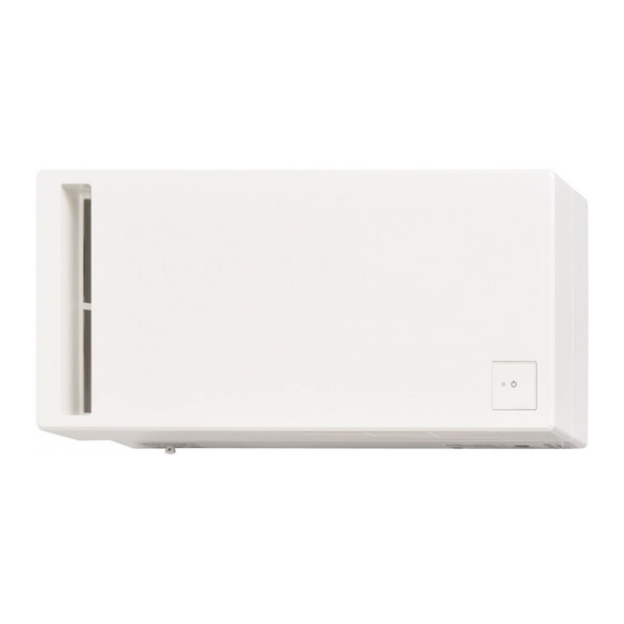
Mitsubishi Electric VL-50S2-E Installation Manual
Hide thumbs
Also See for VL-50S2-E:
- Operating instructions manual (176 pages) ,
- Installation manual (192 pages) ,
- Handbook (44 pages)
Table of Contents
Advertisement
Quick Links
Mitsubishi Lossnay Ventilator
MODEL
VL-50S
-E
2
VL-50ES
2
Installation Manual
Please ensure that the separate "Operating
Instructions" are handed over to the customer. Please
ensure that it is delivered to the customer.
proceeding with the installation work, be sure to
read through these instructions.
can lead to breakdowns and accidents.
and accidents.
licensed electrician employed by the dealer or
contractor.
2
electrician is necessary.
2
1. Safety precautions
Hazards created by mishandling and their
severity are indicated by the following
markers.
Warning:
This applies to mishandling or misoperation
of the product which could lead to a fatal or
serious injury.
Caution:
This applies to mishandling or misoperation
of the product which will lead to an injury or
damage to your home, household effects, etc.
(pull cord type)
-E
(wall switch type)
For Dealer and Contractor
Contents
2. Dimensional outline drawing............... 3
............................................... 12
product but the unit can be mounted
vertically as well.
Warning
- Do not install the unit in
excessively hot areas (40°C or
Prohibited
prone to oily smoke, or where it
could come in contact with organic
solvents.
- Do not disassemble the unit more
than necessary or modify it.
disassemble.
result.
- Do not let the unit get wet.
Do not expose
to water
Eng-1
Page
.............................. 1
........................... 3
............................... 4
..........................
..................
.....
........
............. 7
................ 9
..............................
......................
................... 11
........................ 12
Advertisement
Table of Contents

Subscribe to Our Youtube Channel
Summary of Contents for Mitsubishi Electric VL-50S2-E
- Page 1 Mitsubishi Lossnay Ventilator MODEL VL-50S (pull cord type) VL-50ES (wall switch type) Installation Manual For Dealer and Contractor Please ensure that the separate “Operating Contents Page Instructions” are handed over to the customer. Please ......1 ensure that it is delivered to the customer. 2.
- Page 2 - Do not install the unit and wall - Always place a cover on the switch in a bathroom or other terminal block after construction installed in a highly humid location. work is complete.* bathroom Dust, humidity and the like could result.
-
Page 3: Dimensional Outline Drawing
2. Dimensional outline drawing For horizontal mounting Indoor air Power cable exhaust hole supply supply/ Mounting plate hole exhaust hole pipe Indoor air exhaust hole Indoor air 198.5 exhaust hole Pull cord Unit (mm) For vertical mounting Mounting plate supply knob hole display part comes to the... -
Page 4: Before Installation
4. Before installation 1. Remove the mounting plate. 3. Remove the terminal block cover (VL- 50ES -E only) then remove the mounting plate. package pad.) material such as cardboard. 2. Remove the panel. the plane and pull toward you. or other items do not get inside the unit. Panel Underlay Drain pan end... -
Page 5: Mounting Instructions
5. Mounting instructions 5.1. Wall-hole construction 5.1.3. Pull out the power and connection cables. 5.1.1. Determine the installation For VL-50ES -E only position. 1. Determine the power and connection cable 1. Check the necessary space distance. mounting position diagram on page 4.) 2. - Page 6 Note 5. Cutting air supply/exhaust pipes Without caulking, rainwater comes in. Before caulking hardens, proceed to the mounting instructions.) next procedure. 3. Attach the pipe mounting plate to the air supply/exhaust pipe A. (a) Make sure to insert the air supply/exhaust mounting plate.
- Page 7 Note is downward toward the outdoor side, as Secure the plate in an even position at the four corners. For a concrete wall, use concrete screws Mounting plate (commercially available) to secure the plate. power/communication electric wire takeout position and the mounting plate position. (If the position of the mounting plate is displaced, the power/communication electric Pipe mounting plate...
- Page 8 (b) Use the included aluminum tape (large) to wrap around the connection section between properly secured, drain water may leak. Vertical mounting pipe Pipe mounting plate Unit (mm) 4. Attach the pipe mounting plate to the air 7. Cutting air supply/exhaust pipes supply/exhaust pipe.
-
Page 9: Attaching The Main Unit
9. Secure the air supply/exhaust pipe to the mounting plate. line A. (a) Insert the air supply/exhaust pipe to the screw mounting plate. pipe mounting plate with the tab. (temporary is downward toward the outdoor side, as screw Mounting plate Pipe mounting plate Mounting plate pipe... -
Page 10: Electrical Work
4. Press the main unit into the wall and attach Operation requires a control switch. Have a it with the four screws provided. control switch ready and connect the wiring shown in bold on the connection diagram below. mm or longer. Unit of the power and connection cables and screw the ends in place on the terminal... -
Page 11: Outdoor Construction
2. Fit in the panel horizontally and push. (φ Panel the hood mounting plate to the wall. φ hole. secure the plate. 5.6 Outdoor construction " " mark ウエ 1. Fill the wall hole. Partition mounting plate screws caulking. pipe mounting plates Note (Knockout hole) -
Page 12: Checks After Mounting
6. Checks after mounting Installation pipe should be caulked outside, as should the outdoor hood.) operation will damage the unit.) diagram. Operating out any debris (only in the areas you can see). checks Does the unit make any unusual sounds exhaust pipes and pipe mounting plates do not 7.


Need help?
Do you have a question about the VL-50S2-E and is the answer not in the manual?
Questions and answers