Table of Contents
Advertisement
EVERLAST
POWERARC 210STL
DC Stick/DC Pulse TIG Inverter Welder
CC
GTAW
SMAW
IGBT
~
1
PHASE
DC
120V
240V
Operator's Manual for the PowerARC 210STL
Safety, Setup and General Use Guide
Rev. 2.
1 00-181115– Nov. 18
everlastwelders.com
Specifications and accessories subject to change without notice.
1-877-755-9353
380 Swift Ave. South San Francisco, CA 94080 USA
Advertisement
Table of Contents

Related Manuals for Everlast PowerARC 210ST


Summary of Contents for Everlast PowerARC 210ST
- Page 1 EVERLAST POWERARC 210STL DC Stick/DC Pulse TIG Inverter Welder GTAW SMAW IGBT PHASE 120V 240V Operator’s Manual for the PowerARC 210STL Safety, Setup and General Use Guide Rev. 2. 1 00-181115– Nov. 18 everlastwelders.com Specifications and accessories subject to change without notice.
-
Page 2: Table Of Contents
The owner of this product assumes all liability for its use and maintenance. Everlast Power Equipment INC. does not warrant this product or this document for fitness for any particular purpose, for per- formance/accuracy or for suitability of application. -
Page 3: Letter To The Customer
Your unit registration is important should any information such as product updates or re- calls be issued. It is also important so that we may track your satisfaction with Everlast products and services. If you are unable to register by website, contact Everlast directly through the sales department through the main customer service number in your country. -
Page 4: Everlast Contact Information
Serial number: __________________________ Model number: ____________________________ Date of Purchase___________________________ Everlast US: Everlast consumer satisfaction email: sales@everlastwelders.com Everlast Website: everlastwelders.com Everlast Technical Support: tech@everlastwelders.com Everlast Welding Support: performance@everlastwelders.com Everlast Support Forum: http://www.everlastgenerators.com/forums/index.php Main toll free number: 1-877-755 WELD (9353) Sales: Ext 201 9am—5pm PST M-F Tech Support: Ext 207 9am—5pm EST M-F... -
Page 5: Safety Precautions
Safety Precautions Everlast is dedicated to providing you with the best possible equipment and service to meet the demanding jobs that you have. We want to go beyond delivering a satisfactory product to you. That is the reason we offer technical support to assist you with your needs should an occasion occur. - Page 6 Safety Precautions These safety precautions are for protection of safety and health. Failure to follow these guidelines may result in serious injury or death. Be careful to read and follow all cautions and warnings. Protect yourself and others. Welding and cutting processes produce high levels of ultraviolet (UV) radiation that can cause se- vere skin burn and damage.
- Page 7 Safety Precautions WARNING! Persons with pacemakers should not weld, cut or be in the welding area until they consult with their physician. Some pacemakers are sensitive to EMF radiation and could severely malfunction while welding or while being in the vicinity of someone welding. Serious injury or death may occur! Welding and plasma cutting processes generate electro-magnetic fields and radiation.
- Page 8 Safety Precautions WARNING! Electrical shock can kill. Make sure all electrical equipment is properly grounded. Do not use frayed, cut or otherwise damaged cables and leads. Do not stand, lean or rest on ground clamp. Do not stand in water or damp areas while welding or cutting. Keep work surface dry. Do not use welder or plasma cutter in the rain or in extremely humid conditions.
-
Page 9: Section 1: Specifications
Section 1 Specifications PERFORMANCE AND FEATURE COMPARISON Specification PowerARC 210STL Inverter Type Digitally Controlled IGBT Input Voltage (±10); Phase/Frequency 120/240V; 1PH/50-60Hz Maximum Inrush Amps(I max) 39.2A @120V/ 36.8A @ 240V Maximum Effective (rated running) Amps (I eff) 24A @ 120V/ 22A @ 240V 120V: 35% @ 120A/ 24.8 V 60% @ 90A/ 23.6 V... -
Page 10: Section 2: General Setup And Operation
Section 2 General Setup and Operation 2.1 General Description, Purpose and Features. TIG Features. Additionally the unit has been improved in TIG PowerARC 210STL: function and features. The user now has 2 The PowerARC 210STL is a digitally controlled choices for starting the arc, which can be cho- inverter welder that provides DC stick and DC sen to match the type of operation that is re- TIG welding capability (DC SMAW/DC GTAW) - Page 11 So, this step should not pedal is needed, purchase a NOVA 10k or 22k be overlooked. Use cylinders that are considered pedal for use with the unit direct from Everlast. pure Argon or 100% compressed Argon only. Additionally a torch mounted Amptrol which fea- Medical grade gas is usually not required.
- Page 12 Section 2 General Setup and Operation gas line from the torch into the gas fitting. Ad- round off the top of the crater (the unfilled, bot- just welding current with the amp control knob tom part of the weld puddle). This feature helps to desired amp setting.
- Page 13 Section 2 General Setup and Operation ter starting with 120V, smaller welding elec- safety practices should be employed at all times trodes may need to be used to achieve a better when the VRD is required to be used. Note that start.
- Page 14 (after the required before replacing the covers. Do not pinch any amount of rest, if any), contact Everlast. wires when reinstalling the covers. Wear safety glasses to prevent eye injury from flying parti-...
-
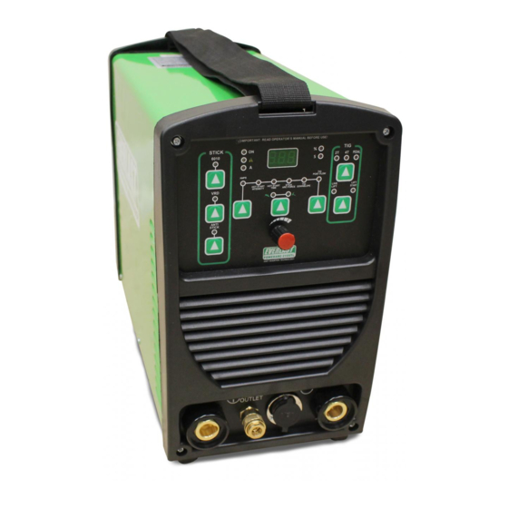
Page 15: Front Panel
ARC FORCE DOWNSLOPE START LIFT START ANTI STICK EVERLAST PowerARC 210STL CONTROL GAS OUTLET 1. E6010 Stick function for welding with cellulose rods. the work clamp is connected here. 2. VRD function, when engaged, reduces Stick OCV for safe- 11. The Shielding Gas Quick Connect Coupling is used to con- ty where required. -
Page 16: Rear Panel
General Setup and Operation PowerARC 210STL Rear Panel View CONSULT A LICENSED ELECTRICIAN AND LOCAL CODES BEFORE WIRING YOUR FACILITY FOR YOUR UNIT! EVERLAST IS NOT RESPONSIBLE FOR DAMAGE OR INJURIES RESULTING FROM IMPROPER WIRING. MAIN POWER SWITCH GAS CONNECTION 1x1110/220V... -
Page 17: Stick Welding Configuration
HOT START INTENSITY HOT START STICK LIVE LIFT TIME ARC FORCE PREFLOW DOWNSLOPE LIFT START START AMPS ANTI STICK EVERLAST PowerARC 210STL TORCH (+) WORK (-) CONTROL GAS OUTLET POLARITY: STICK MODE: TORCH POSITIVE (+), WORK NEGATIVE(-) WORK CLAMP TORCH/ELECTRODE HOLDER... -
Page 18: Tig Torch Configuration
FROM SWITCH NOTE: FOOT PEDAL IS OPTIONAL. Purchase a long life NOVA foot pedal or torch mounted NOVA Slider Amp Control direct from Everlast if needed to adjust amps while welding. Additionally, optional TIG torches, including high quality NOVA torches are also available for purchase from Everlast. -
Page 19: Gas Connection
Section 2 General Setup and Operation PowerARC 210STL Gas Connection Start all fitting threads with fingers and turn clockwise until the male fitting begins to seat. Then, use only a wrench to t ight- en fittings. Do not use pliers or any type of gripping device with locking jaws or serrated teeth. When tightening the tubing fitting to the welder’s CGA 5/8”... -
Page 20: Wire Connection
“hot” and the green serving as the ground or damage and malfunction may occur. Do not remove the NEMA 6-50 plug to operate on 120V. Use the 240V-120V adapter available from Everlast to adapt the plug to standard 120V power. No other wiring is required. -
Page 21: Stick Operation Technique/Information
Section 2 General Setup and Operation STICK OPERATION STARTING METHODS Tapping Method Scratch/Match Method Striking the Arc Make sure the unit is turned on and the startup cycle has finished. Select the Stick icon on the Process Selector. Make sure the electrode holder is in the Positive connector and the work clamp is in the negative connector. Select the Amp level desired. - Page 22 General Setup and Operation Section 2 Basic TIG Operation General Setup. The process to set up the welder running slowly without filler metal first. Keep the for the basic TIG mode is much less involved than torch head inclined away from the direction of trav- for basic MIG or Stick.
-
Page 23: Basic Tig Operation
General Setup and Operation Section 2 Basic TIG Operation need to change your settings. Practice feeding the filler wire without actually welding. Manipulating filler wire without actually welding. Manipulating the wire takes practice and concentration at first. the wire takes practice and concentration at first. The wire should be held so that a flicking motion of The wire should be held so that a flicking motion two fingers and the thumb can propel the rod for-... -
Page 24: Tig Arc Start And Tig Tips
General Setup and Operation Section 2 Note: A TIG lift start should use a nearly seamless motion. Use a light touch and a quick motion for best results. LIFT START OPERATION <1/8” Position the edge of the ceramic cup on the metal. Press and hold the torch switch or press the foot pedal. Wait for the Pre-flow to start. -
Page 25: Tungsten Preparation
General Setup and Operation Section 2 TUNGSTEN PREPARATION 1. Use a dedicated grinding wheel or contamination may re- sult. Do not breath grinding dust! Wear eye protection and gloves. 2. Hold Tungsten firmly. 3. Grind perpendicular to grinding wheel face. Allow tungsten to grind away slowly, creating point. -
Page 26: Kit Contents
General Setup and Operation Section 2 PowerARC 210STL Box Contents Qty. Description Tong style Stick electrode holder and cable, 10 ft Steel work clamp and cable, 10 ft PowerARC 210STL DC Stick/DC TIG Inverter welder Manual (may be downloaded from website for free) 240V-120V Adapter (optional in some markets) NOTE: Kit contents, appearance, size and quantity are subject to change without notice. -
Page 27: Tig Torch Assembly
General Setup and Operation Section 2 EXPANDED VIEW OF TIG TORCH (Actual appearance may vary slightly from what is listed.) PARTS FOR 17/26 Series Torch ( STYLE MAY VARY) QTY. Long Back Cap with O-Ring Short Back Cap Opt. Torch Head Insulator Collet 1/16, 3/32, or 1/8”... -
Page 28: Trouble Shooting
Slight whine or squeal to arc or to welder while turned on. Normal. Sound may vary. Circuit breaker trips. Wiring fault. Too small of wire or circuit breaker. Welder internal short. Contact Everlast Technical Support before resuming use. Error Code Meaning Possible Cause Over Voltage/Under Voltage Check Power Source, Correct Wiring. -
Page 29: Foot Pedal Pin-Outs
Section 3 Trouble Shooting 7 PIN CONNECTOR FOR FOOT PEDAL 10kΩ For NOVA Bridge to 7 To Pedal or Torch Switch Bridge to 6 To Pedal or Torch Switch The welder will accept 10k to 22k Ohm potentiometers. - Page 30 NOTES:...
Need help?
Do you have a question about the PowerARC 210ST and is the answer not in the manual?
Questions and answers