Table of Contents
Advertisement
Quick Links
Download this manual
See also:
User Manual
Advertisement
Table of Contents

Subscribe to Our Youtube Channel
Related Manuals for Gefen EXT-DVI-148


Summary of Contents for Gefen EXT-DVI-148
- Page 1 ® 1:8 DVI Distribution Amplifier EXT-DVI-148 User Manual...
- Page 2 HDTV systems of all sizes with hard-working solutions that are easy to implement and simple to operate. The Gefen Extender for HDMI 1.3 Over One Fiber with IR The 1:8 DVI Distribution Amplifier is the perfect solution for anyone who needs to send one source of digital high definition video to multiple displays at the same time.
-
Page 3: Operation Notes
OPERATION NOTES READ THESE NOTES BEFORE INSTALLING OR OPERATING THE 1:8 DVI DISTRIBUTION AMPLIFIER • When using the 1:8 DVI Distribution Amplifier, it is important to use devices/ displays that have similar or compatible resolutions/features. This will ensure that the single video/audio signal produced by the source device is accepted by all of the connected output devices/displays. - Page 4 FEATURES Features • Distributes easily up to eight DVI/HDMI displays • Maintains 480i, 480p, 720p, 720i, and 1080i, 1080p resolutions • Maintains highest DVI single link video resolution • Maintains highest DVI digital audio signal • Supports HDCP compliant devices •...
-
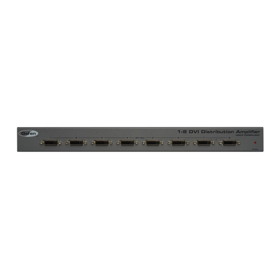
Page 5: Panel Layout
PANEL LAYOUT... -
Page 6: Panel Descriptions
PANEL DESCRIPTIONS DVI Out (1 - 8) Connect a DVI display to each of these DVI ports. Power This LED indicator will glow bright red when the included power supply is connected to the 1:8 DVI Distribution Amplifier and the AC power cord is connected to an available electrical outlet. - Page 7 1:8 DVI Distribution Amplifier. Connect the opposite end of the AC power cord into an available electrical outlet. Wiring Diagram for the 1:8 DVI Distribution Amplifier DVI CABLE Computer Splitter Monitor Monitor Monitor Monitor Monitor Monitor Monitor Monitor EXT-DVI-148...
-
Page 8: Edid Management
EDID MANAGEMENT EDID: What is it and what is it used for? Under normal circumstances, an source device (digital and analog) will require information about a connected device/display to assess what resolutions and features are available. The source can then cater its output to send only resolutions and features that are compatible with the attached device/ display. - Page 9 EDID MANAGEMENT EDID Modes The diagrams below illustrate the DIP switch bank for each EDID mode. Use DIP switches 1, 2, and 5 to select the desired EDID management mode. EDID Mode 0 • EDID is copied from the active device connected to DVI Out 1. EDID Mode 1 •...
- Page 10 EDID MANAGEMENT EDID Mode 4 • Same as EDID Mode 3 and adds basic 2-channel audio support. EDID Mode 5 • Same as EDID Mode 3; adds full audio support up to 5.1 channels. EDID Mode 6 (Default Setting) • EDID is generated based on common audio and video features of all the connected devices.
-
Page 11: Specifications
SPECIFICATIONS Maximum Pixel Clock................165 MHz Input Video Signal................1.2 volts p-p Input DDC Signal................5 volts p-p (TTL) Input Video Connector........(1) DVI, 29-pin, female (digital only) Output Video Connector........(8) DVI, 29-pin, female (digital only) Power Consumption ................60W (max.) Power Supply .....................24V DC Dimensions (W x H x D) ....17”...
Need help?
Do you have a question about the EXT-DVI-148 and is the answer not in the manual?
Questions and answers