Table of Contents
Advertisement
Quick Links
Advertisement
Table of Contents

Subscribe to Our Youtube Channel
Related Manuals for Gefen EXT-DVI-248


Summary of Contents for Gefen EXT-DVI-248
- Page 1 ® 2x8 DVI DA E X T - D V I - 2 4 8 U S E R M A N U A L www.gefen.com...
- Page 2 Notice Gefen Inc. reserves the right to make changes in the hard ware, packaging and any accompanying doc u men ta tion without prior written notice. The 2:8 DVI Distribution Amplifi er is a trademark of Gefen Inc.
-
Page 3: Table Of Contents
TABLE OF CONTENTS Introduction Operation Notes Panel Descriptions Connecting the 2x8 Distribution Amplifi er EDID Management Feature EDID Management Modes RMT-2IR Installation IR Code Confi guration RS-232 Serial Communication RS-232 Serial Communication Commands Specifi cations Warranty... -
Page 4: Introduction
The Gefen 2:8 DVI distribution amplifi er is connected with a DVI (male to male) cable from the DVI graphic source to the distribution amplifi er input. There are eight DVI outputs in each module. -
Page 5: Operation Notes
OPERATION NOTES READ THESE NOTES BEFORE INSTALLING OR OPERATING THE 2:8 DVI DISTRIBUTION AMPLIFIER SYSTEM • All the monitors connected to the 2:8 DVI Distribution Amplifi er must be able to run at the same native resolution. The 2:8 DVI Distribution Amplifi er does not scale the video. •... -
Page 6: Panel Descriptions
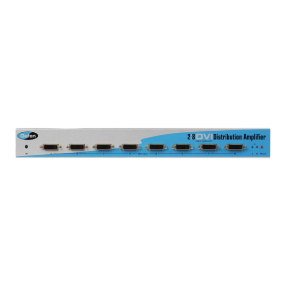
2:8 DVI DISTRIBUTION DA FRONT PANEL DESCRIPTION IR Eye DVI Output IR Extender Power RS-232 Input Input DVI Input Input... - Page 7 CONNECTING AND OPERATING THE 2X8 DVI DA How to Connect the 2x8 DVI DA to your devices 1 Connect the supplied cable from the HDTV DVI source into the 2x8 DVI DA input. 2 Connect the cables from your displays (monitor or projector) into the DVI outs of the 2x8 DVI DA.
-
Page 8: Edid Management Feature
EDID MANAGEMENT FEATURE EDID. What is it and what is it used for? Under normal circumstances, an source device (digital and analog) will require information about a connected device/display to assess what resolutions and features are available. The source can then cater its output to send only resolutions and features that are compatible with the attached device/display. -
Page 9: Edid Management Modes
EDID MANAGEMENT MODES v. 2015d EDID Modes The diagram below illustrates the 8 DIP switch bank. DIP SWITCH Function EDID Mode EDID Mode IR Channel IR Channel EDID Mode EDID Mode Use DIP switches 1, 2, 5, and 7 to select the desired EDID management mode. EDID Mode 0 (Switch 1=OFF Switch2=OFF Switch5=ON) •... -
Page 10: Rmt-2Ir Installation
RMT-2IR INSTALLATION 1. Remove battery cover from the back of the RMT-2IR remote. 2. Verify that DIP switches 1 & 2 are in the down (OFF) position (please see page 8). 3. Insert the battery, hold the battery so that you can see the positive side facing up. The side that is not marked must be facing down. -
Page 11: Ir Code Confi Guration
IR CODE CONFIGURATION Why would I need to change the remote channel? In some instances, the 2x8 DVI Distribution Amplifi er may use IR codes that confl ict with other IR remote control devices. The unit may switch inputs when another brand IR remote control is used or the RMT-2IR may cause other brand IR controlled devices to behave unexpectedly. -
Page 12: Rs-232 Serial Communication
RS-232 SERIAL COMMUNICATION What features are available via the RS-232 serial communications port? The 2x8 DVI Distribution Amplifi er can accept commands through the RS-232 serial communications port located on the rear panel. The current RS-232 control features are: • Switching/routing of inputs to outputs without the RMT-2IR remote control. -
Page 13: Rs-232 Serial Communication Commands
RS-232 SERIAL COMMUNICATION COMMANDS Switching/Routing Binary Table ASCII RMT-2IR Binary Button 0011 0001 0011 0010 EDID Management Modes All DIP switches inside the unit must be in their default OFF position. Use the ASCII commands below to change the EDID modes. For a description of each mode please see page 6. -
Page 14: Specifi Cations
SPECIFICATIONS Video Amplifi er Bandwidth ................. 1.65 MHz Single Link Range ................1080p, 1920 x 1200 Vertical Frequency Range ..................60 Hz DVI Input/Output Connector Type ........DVI-I 29 pin female (digital only) Power Consumption ................60 Watts (max.) Power Supply ......................24VDC Dimensions .................. - Page 17 Rev X2 20600 Nordhoff St., Chatsworth CA 91311 1-800-545-6900 818-772-9100 fax: 818-772-9120 www.gefen.com support@gefen.com...
Need help?
Do you have a question about the EXT-DVI-248 and is the answer not in the manual?
Questions and answers