JVC gy-dv5100 Instructions Manual
Hide thumbs
Also See for gy-dv5100:
- Instructions manual (103 pages) ,
- User manual (103 pages) ,
- Instructions manual (104 pages)
Table of Contents
Advertisement
Quick Links
Download this manual
See also:
User Manual
DV CAMCORDER
GY-DV5100
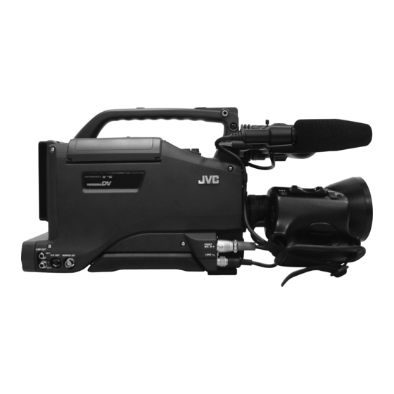
* The illustration shows the GY-DV5100 DV Camcorder with the optional lens, viewfinder and Microphone attached.
Thank you for purchasing this JVC product. Before operating
this unit, please read the instructions carefully to ensure the
best possible performance.
For Customer Use :
Enter below the Serial No. which is located on the body.
Retain this information for future reference.
Model No. GY-DV5100
Serial No.
Downloaded From CamcorderManual.com JVC Manuals
INSTRUCTIONS
INTRODUCTION
CONTROLS,
INDICATORS AND
CONNECTORS
BASIC SYSTEM
CONNECTIONS AND
ADJUSTMENTS
POWER SUPPLY
PREPARATIONS
SETTING AND
ADJUSTMENTS
BEFORE SHOOTING
SHOOTING
OPERATION
PLAYBACK MODE
USING EXTERNAL
COMPONENTS
TIME CODE
OPERATION
MENU SCREENS
FEATURES OF THE
CAMERA SECTION
OTHERS
LWT0230-001A-H
Advertisement
Table of Contents

Related Manuals for JVC gy-dv5100


Summary of Contents for JVC gy-dv5100
- Page 1 FEATURES OF THE CAMERA SECTION OTHERS * The illustration shows the GY-DV5100 DV Camcorder with the optional lens, viewfinder and Microphone attached. Thank you for purchasing this JVC product. Before operating this unit, please read the instructions carefully to ensure the best possible performance.
-
Page 2: Important Safeguards
19. Upon completion of any service or repairs to this appliance, ask the service technician to perform routine safety checks to determine that the appliance is in safe operating condition. Downloaded From CamcorderManual.com JVC Manuals... -
Page 3: Safety Precautions
● Consult the dealer or an experienced radio/TV technician for help. CAUTION CHANGES OR MODIFICATIONS NOT APPROVED BY JVC COULD VOID USER’S AUTHORITY TO OPERATE THE EQUIPMENT. THIS DEVICE COMPLIES WITH PART 15 OF THE FCC RULES. -
Page 4: Main Features
● The transient section between scenes recorded on other Other use may infringe on the rights of copyright holders. ● JVC cannot assume liabilities that may derive from the units and those recorded on this unit may appear impossibility of normal recording or playback of video or disturbed. -
Page 5: Table Of Contents
6-6 White Balance Adjustment ........50 13-2 Troubleshooting ............99 6-7 Audio Input Signal Selection ........51 13-3 Hour Meter Display ..........100 6-8 Recording Level Adjustment ........52 13-4 Specifications ............101 6-9 Monitoring Audio during Recording ......53 Downloaded From CamcorderManual.com JVC Manuals... -
Page 6: Introduction
Depending on circumstances the tape may also be damaged. ● Vibrations Colors may fail to appear and/or the image and sound may be disturbed during VTR playback in locations subjected to strong vibrations. Downloaded From CamcorderManual.com JVC Manuals... -
Page 7: Routine And Periodical Maintenance
1-2 Routine and Periodical Maintenance The GY-DV5100 incorporates precision mechanical parts, which will collect dirt, wear out and deteriorate as the unit is used. After the unit has been used for a long period even in a normal environment, the heads, drums and tape transport mechanisms also collect dirt. -
Page 8: Videocassette To Be Used
– – 1-5 Battery Pack to be Used The GY-DV5100 can use any of the following battery packs. * A flat shape type battery pack cannot be connected directly ● Flat shape type to the camera. It is necessary to mount the optional battery ●... -
Page 9: Condensation
As far as possible, use the unit under conditions where the Smear temperature of the unit does not increase. (Vertical pale streaking appearing at high luminous object) High luminous object (Electric light, sunlight, etc.) Blooming (Blurring in highlight) Monitor screen Downloaded From CamcorderManual.com JVC Manuals... -
Page 10: Controls, Indicators And Connectors
FRONT MIC +48V switch is set to the “ON” side when the provided microphone should be used. When using a microphone other than a phantom microphone, first set the FRONT MIC +48V switch to “OFF” before connecting the microphone. Downloaded From CamcorderManual.com JVC Manuals... - Page 11 ☞ See “Attaching the Zoom Lens” on page 32. [FILTER] Color temperature conversion filter control knob This knob switches the internal color temperature filters. (3200K, 5600K + 1/8ND, 5600K, 5600K + 1/64ND) ☞ See “Camera Settings” on page 47. Downloaded From CamcorderManual.com JVC Manuals...
-
Page 12: Right Side Section
To change the setting value of the item, press this dial. When the setting value starts blinking, turn this dial upward or downward to change the setting. ☞ See “Setting Menu Screens” on page 72. Downloaded From CamcorderManual.com JVC Manuals... - Page 13 (ALC) (one of the full auto shooting functions) will be made inactive, so that the LOLUX mode is given preference (FAW still remains active). ☞ See “GAIN BOOST UNDER LOLUX CONDITION” on page 92. Downloaded From CamcorderManual.com JVC Manuals...
- Page 14 ● Select the VTR mode to playback or to input the DV signal It is effective especially in the following cases: from the DV connector 7 on page 19. ● When the power is turned on, the mode becomes the Camera mode. Downloaded From CamcorderManual.com JVC Manuals...
- Page 15 MANUAL : The audio level can be adjusted with the CH-2 Only image displayed → Characters shown enlarged AUDIO LEVEL control 7. ↑ Image and characters displayed ← Downloaded From CamcorderManual.com JVC Manuals...
- Page 16 1 on ☞ See “TC/UB/CLOCK Menu Screen” on page 83. page 15 or the PHONES 5 jack on page 19. CH-1 : The CH-1 channel audio is output. Downloaded From CamcorderManual.com JVC Manuals...
-
Page 17: Left Side Section
(1/2) menu screen is set to ON, the same on-screen indications as those on the viewfinder will be shown on the external monitor. (Black and white indications) ● The setup signal can be selected also for the EE output signal of the DV input. Downloaded From CamcorderManual.com JVC Manuals... -
Page 18: Top Section
STOP, playback operations become possible. mode. When a blank part (unrecorded part) on the tape is detected, the unit enters the STILL status in the VTR mode and the Standby status in the Camera mode. Downloaded From CamcorderManual.com JVC Manuals... -
Page 19: Rear Section
1 [TALLY] Tally lamp The audio output level is adjusted with the Audio monitor volume control 1 on page 12. This lamp lights up when the GY-DV5100 enters the record mode. It blinks during the transition to the record mode. MEMO: ●... - Page 20 BREAKER button before turning the power ON again to put the camera in the operating status. If the unit still does not work normally, please consult the person in charge of professional video equipment at your nearest JVC-authorized service agent. Downloaded From CamcorderManual.com JVC Manuals...
-
Page 21: Indications On The Lcd Monitor And In The Viewfinder
SHUTTER 1/1000 WHITE BAL IRIS LEV. NORMAL FILTER 3200K ZEBRA 70%–80% REMAIN 1 2 3 m i n ( AUDIO 32K( CH1 M CH2 M ) 01/02/03 01:23:45 STBY 01/02/03 01:23:45 STATUS 3 STATUS 2 Downloaded From CamcorderManual.com JVC Manuals... - Page 22 F VTR mode indication are turned off and the LCD BRIGHT indicator is displayed. (Example) BRIGHT +5 Numeric value : Any of –5, –4, –3, –2, –1, 0, +1, +2, +3, +4, +5. Downloaded From CamcorderManual.com JVC Manuals...
- Page 23 ☞ See “AUDIO REF. LEVEL” on page 80. CH 1 ■ ■ ■ ■ ■ CH 1 ■ ■ ■ ■ ■ – – – + CH 2 ■ ■ ■ ■ ■ – – – + Downloaded From CamcorderManual.com JVC Manuals...
- Page 24 This screen only displays date and time, event display and warning indications. * Whether or not date and time should be displayed and the display style are set on the TIME/DATE MENU screen. ☞ page 45 “Displaying the Time and Date on the Screen” Downloaded From CamcorderManual.com JVC Manuals...
- Page 25 SLOW+3: About ×0.5 speed) During variable playback in reverse direction (SLOW–1: About ×–0.1 speed, SLOW–2: About ×–0.2 speed, SLOW–3: About ×–0.5 speed) Event display BLANK SEARCH : Indicates that blank search operation is in progress. Downloaded From CamcorderManual.com JVC Manuals...
- Page 26 DF : During playback of a tape recorded in drop frame mode. NDF : During playback of a tape recorded in non-drop frame mode. Time Code Indicator Displays time code. During warnings, messages are displayed here. ☞ see page 27 Downloaded From CamcorderManual.com JVC Manuals...
- Page 27 Displayed in case abnormalities occur in the VCR, or when condensation occurs in the unit. For details, ☞ see page 97. (Example) 7001 DRUM MOTOR FAILURE * When displaying enlarged characters, only LOW VOLTAGE and VTR WARNING are displayed. Downloaded From CamcorderManual.com JVC Manuals...
- Page 28 The Menu Setting Screen appears when the STATUS button is pressed CAMERA PROCESS for 1 second or more. AUDIO/VIDEO.. ☞ See “Setting Menu Screens” on page 72. LCD/VF.. TC/UB/CLOCK.. OTHERS.. FILE MANAGE.. MENU ALL RESET CANCEL EXIT TOP MENU screen (Camera mode) Downloaded From CamcorderManual.com JVC Manuals...
-
Page 29: Lens (Optional)
● Pressing the “W” section of this lever increases the angle of the lens for a wider shooting angle. ● Pressing the “T” section of this lever narrows the lens angle perspective for telephoto shots. ● Pushing harder changes the speed of the zoom. Downloaded From CamcorderManual.com JVC Manuals... -
Page 30: Inch Viewfinder (Optional)
The eyepiece can be opened to allow direct observation of the viewfinder screen. 9 Eyepiece focusing ring Loosen this ring to move the eyepiece back or forth to adjust the diopter. ☞ See “Attaching the Viewfinder” on page 32. Downloaded From CamcorderManual.com JVC Manuals... -
Page 31: Basic System Connections And Adjustments
Please use the Focus Manual Unit (FMM-8, CHF-3, CFC-12-990) manufactured by Fujinon. 2 The optional service parts are required to attach the SHOULDER BELT. 1. PIN (SC46310-001) × 2 2. SPACER (SC46311-001) × 2 For details, please consult your JVC authorized dealer. Downloaded From CamcorderManual.com JVC Manuals... -
Page 32: Attaching The Zoom Lens
Hole back focus. ● Set the GY-DV5100's power switch to “OFF” before the zoom lens is attached or detached. When unplugging the cable connector, first remove the lens itself. Then grasp this portion and pull out. -
Page 33: Attaching The Microphone (Provided)
● When the light mounted on the camera is used at the same time, if the microphone in use has a long sound collecting section, the microphone’s shadow may appear in the image. FRONT MIC IN Microphone cable Downloaded From CamcorderManual.com JVC Manuals... -
Page 34: Attaching The Tripod Base (Provided)
MENU AUDIO LEVEL PULL OPEN FRONT AUTO IRIS FULL AUTO BLACK LOLUX REAR CH-1 CH-2 CH-1 CH-2 MODE AUDIO INPUT BACK L STRETCH AUDIO SELECT NORMAL NORMAL CH-1 CH-2 SPOT L COMPRESS AUTO MANUAL POWER Downloaded From CamcorderManual.com JVC Manuals... -
Page 35: Power Supply
DC power is applied. Then switch ON again. ● If the GY-DV5100 is left with the battery pack attached, a small amount of power is consumed even if the POWER switch on the GY-DV5100 is set to OFF. Remove the battery pack when the GY-DV5100 is not going to be used. - Page 36 To use the NP-1 type battery, remove the Anton-Bauer Battery holder and attach the NP-1 type battery holder to the camera. Use the following battery case. Battery case: SCV2978-002 For details, please consult your JVC authorized dealer. Detaching the Anton-Bauer Battery Holder and Attaching the Battery Case CAUTION: Be careful of pins.
- Page 37 Insert the battery pack into the battery case with its electrodes facing the unit. Close the battery case cover. Lock release Be sure to set the POWER switch to OFF before replacing lever the battery pack. Downloaded From CamcorderManual.com JVC Manuals...
-
Page 38: Remaining Battery Power Display
After the remaining battery power warnings appear, the Battery lamp BATT ALARM GY-DV5100 automatically stops operation if the battery power operation is continued. REC/ALARM lamp Operating Time with Battery Pack ● Battery operating time may differ depending on the age of... -
Page 39: Preparations
STOP. VTR mode The GY-DV5100 enters the VTR mode. The camera image will not be displayed in the viewfinder or on the LCD monitor. When a videocassette is loaded, the GY-DV5100 enters the stop mode. -
Page 40: Cassette Loading And Unloading
Cassette cover ● A cassette cannot be loaded or unloaded while the GY-DV5100 is in POWER OFF mode. ● Use a standard DV videocassette or a MiniDV videocassette. ● Press at the center portion of the cassette back and insert the cassette tape straight into the slot. - Page 41 ● Do not leave the unit for a long period with the cassette cover open. Dirt or other foreign objects may enter the VCR section and cause malfunction. ● Do not touch the cassette insertion slot or cassette during the eject operation. This could result in damage. Downloaded From CamcorderManual.com JVC Manuals...
-
Page 42: Viewing The Lcd Monitor
: Adjust the LCD PEAKING item on the LCD/VF (2/2) menu. LCD BRIGHT +/– button LCD/VF (2/2) menu ––– LCD/VF(2/2) ––– BATTERY INFO VOLTAGE TAPE REMAIN TC/UB AUDIO LCD COLOR NORMAL LCD PEAKINGS NORMAL PAGE BACK Downloaded From CamcorderManual.com JVC Manuals... -
Page 43: Setting, Displaying And Recording The Date And Time
The TIME STYLE, SEC DISPLAY and DATE STYLE items then press the SHUTTER dial. ● The setting area stops blinking and the setting is can also be set and changed after the date and time have entered. been set. Downloaded From CamcorderManual.com JVC Manuals... - Page 44 To return to the normal screen, use either of the following methods. Press the STATUS button Time (Hour:Min) Return to the TOP MENU screen and then select the EXIT item from the TOP MENU screen before pressing the SHUTTER dial. Downloaded From CamcorderManual.com JVC Manuals...
-
Page 45: Displaying The Time And Date On The Screen
PAGE BACK BARS+CAM : Date and time data are recorded when color bars and camera image are output. : Date and time data are not recorded. MEMO: DATE REC cannot be set during recording. Downloaded From CamcorderManual.com JVC Manuals... -
Page 46: Charging The Built-In Battery
In this case, recharge the built-in battery and then set the date and time and time code data again. However, it is possible to use the GY-DV5100 even if the bulit-in battery is discharged but the date and time and time code data cannot be recorded. -
Page 47: Setting And Adjustments Before Shooting
● When the DATE REC item on the TIME/DATE screen is set to “BARS” or “BARS+CAM” while ASPECT RATIO item in CAMERA OPERATION menu is set to LETTER, the screen size will be fixed at an aspect ratio of 4:3. Downloaded From CamcorderManual.com JVC Manuals... -
Page 48: Viewfinder Adjustment
Color video monitor Connect a color video monitor to the MONITOR OUT connector of the GY-DV5100. Set the COLOR BARS/CAMERA/AUTO KNEE switch to BARS to output the color bar signal (SMPTE type color bars). -
Page 49: Back Focus Adjustment
Tighten the back focus ring retaining knob to secure the ring. MEMO: ACCU FOCUS can also be used in the above step 3 . Siemens star chart Downloaded From CamcorderManual.com JVC Manuals... -
Page 50: White Balance Adjustment
10 seconds for the FAW be allocated to one of the white balance switching switches adjustment to be completed. Do not shoot within this A, B, or PRESET. interval. ☞ See “CAMERA OPERATION menu screen” on page 75. Downloaded From CamcorderManual.com JVC Manuals... -
Page 51: Audio Input Signal Selection
(LINE/MIC) switch ■ Selecting the REAR AUDIO IN connector The GY-DV5100 is provided with the FRONT MIC IN connector and the REAR AUDIO IN connector for audio input. Select the sound to be input to the REAR AUDIO IN connector Two channels of sound can be recorded on the tape in digital using the REAR AUDIO IN (LINE/MIC) switch. -
Page 52: Recording Level Adjustment
● Adjust so that the peak level does not exceed the –3dB point when a loud sound is input. Downloaded From CamcorderManual.com JVC Manuals... -
Page 53: Monitoring Audio During Recording
The volume of the alarm tone is set with the ALARM VR LEVEL item on the OTHERS (2/2) menu screen. (OFF/LOW/MIDDLE/HIGH) * Do not increase the audio monitoring volume excessively; otherwise howling with the camera microphone may occur. Downloaded From CamcorderManual.com JVC Manuals... -
Page 54: Shooting Operation
7-1 Basic Recording Operation OPEN knob Set the POWER switch to ON. ● Power is supplied to the unit. The CAM indicator lights up. The GY-DV5100 is in the Camera mode when the CAM indicator is on. OPEN EDITSEARCH MONITOR... - Page 55 ● If the VTR trigger button is pressed very quickly and repeatedly, or the POWER switch is moved immediately after the trigger button is pressed, the viewfinder REC indicator lamp may blink and the GY-DV5100 may not enter the record mode. To remedy this condition set the POWER switch to OFF and wait for 5 seconds or more before turning the power on again.
-
Page 56: Searching For Recorded Scenes (Edit Search)
When the EDIT SEARCH – button is released, the standby mode is reengaged. FIL1 F5.6 12.2V MEMO: ED.FWD 01/02/03 AM01:23:45 ● Block noise may appear and the image may freeze during search. ED.FWD: Forward search ED.REV: Reverse search Downloaded From CamcorderManual.com JVC Manuals... -
Page 57: If The Record-Standby Mode Continues
STOP 01/02/03 AM01:23:45 VTR mode indication 7-4 Checking Recorded Contents in Record-Standby Mode (Recording Check Function) This function is available only when the GY-DV5100 is in the RET button standby mode. In the record-standby mode, approximately 2 seconds of the last recorded portion can be played back. -
Page 58: Header Rec Function
Sets the duration for recording of the black video signal and BARS TIME 30SEC mute audio signal. [Setting range: 0 to 99 sec] BLACK TIME 30SEC PAGE BACK The TC/UB/CLOCK menu screen returns when the SHUTTER PAGE BACK dial is pressed. Downloaded From CamcorderManual.com JVC Manuals... - Page 59 ● The test tone (1 kHz sine-wave) recorded in the color bar FREE RUN : Continuous running. REC RUN or REGEN: Runs only during REC. section will be recorded unrelated to the setting for the TEST TONE item on the AUDIO/VIDEO menu screen. Downloaded From CamcorderManual.com JVC Manuals...
-
Page 60: Recording The Color Bars
Black Magenta Black Cyan Black White the TEST TONE item on the AUDIO/VIDEO menu screen. ● Color bars will not appear when Full Auto is set to ON or when in the VTR mode. Black White Black Downloaded From CamcorderManual.com JVC Manuals... -
Page 61: Playback Mode
POWER switch MODE switch MEMO: MEMO: ● The GY-DV5100 can play back the following three types ● In the VTR mode, the camera image is not output on the of videocassettes: LCD monitor, in the viewfinder or through the video output •... -
Page 62: Fast-Forward, Rewind
(When the Status screen is shown.) ● To prevent that images will be missing, overwrite from 12.2V about 3 seconds before the point where the previous BSRH 01/02/03 AM––:––:–– recording ends. Blank search operation indicator Downloaded From CamcorderManual.com JVC Manuals... -
Page 63: Variable Slow Playback
■ To return to the normal playback mode, press the PLAY button. ■ To stop, press the STOP button. ■ The amount of frames advanced in slow motion playback can be set in STEP SLOW MODE on page 86. Downloaded From CamcorderManual.com JVC Manuals... -
Page 64: Outputting Ch-3, Ch-4 Channel Audio
CH-1 and CH-2. (4-channel recording is possible in the case of DV input.) When the GY-DV5100 is used for playback of a tape that was recorded on another unit with audio recorded on the CH-3 and CH- 4 channels, the AUDIO SELECT item on the AUDIO/VIDEO menu screen must be set. -
Page 65: Using External Components
9. USING EXTERNAL COMPONENTS 9-1 Connecting a Video Component with DV Connector Connecting the GY-DV5100 to another video component equipped with DV I/O connector (IEEE1394 standard) using a DV cable (optional) enables dubbing of digital signals with high picture quality and high-quality sound. - Page 66 Backup Recording of the GY-DV5100's Camera Image and Sound Through the DV Connector The GY-DV5100’s camera image and sound can be recorded for backup on another component that is equipped with DV connector. Recording operation is performed on the backup equipment simultaneously with performance of the recording operations on the GY-DV5100.
-
Page 67: Time Code Operation
10. TIME CODE OPERATION The GY-DV5100 records SMPTE-standard time codes and user’s bits. In the play mode or the record mode, the reproduced time codes or user’s bits are shown on the LCD monitor or in the viewfinder. ● Time code data cannot be output through the unit’s connectors. -
Page 68: Presetting And Recording Of Time Code
To compensate for this difference, the mode called “drop mode” drops frame 00 and 01 for every minute not divisible by 10. The “non-drop frame mode” is when no frames are dropped and the actual time shift is neglected. Downloaded From CamcorderManual.com JVC Manuals... -
Page 69: Time Code Presetting Procedure
1 Rotate the SHUTTER dial to align the cursor ( ) with the TC or UB PRESET item, and then press the SHUTTER dial. 2 Rotate the SHUTTER dial to select ZERO PRESET as the setting value, and then press the SHUTTER dial. Downloaded From CamcorderManual.com JVC Manuals... -
Page 70: Recording Time Codes In Continuation Of Time Codes Recorded On Tape
TC GENE switch 10-4 Reproducing Time Codes The GY-DV5100 incorporates a time code reader. During playback, the time code or user’s bit data recorded on the tape is displayed on the LCD monitor or in the viewfinder. (Status screen) Setting Playback time code indication ☞... -
Page 71: Menu Screens
STEP SLOW MODE FRAME NEXT PAGE DRUM HOUR 000200H PAGE BACK OTHERS screen OTHERS screen ––– FILE MANAGE ––– LOAD FILE LOAD CANCEL STORE FILE STORE CANCEL RESET FILE RESET CANCEL PAGE BACK FILE MANAGE screen Downloaded From CamcorderManual.com JVC Manuals... -
Page 72: Setting Menu Screens
CH-1 CH-2 SPOT L COMPRESS AUTO MANUAL Set the mode of the GY-DV5100 with the MODE switch. (Camera mode or VTR mode) POWER Press the STATUS button for 1 second or longer. ● The TOP MENU screen appears. STATUS button Select the menu screen to be set. -
Page 73: File Manage Menu Screen
When you rotate the SHUTTER dial to make EXECUTE in the setting value area blink and then press the SHUTTER dial, the set values are reset. The power is automatically turned OFF and ON again. Downloaded From CamcorderManual.com JVC Manuals... -
Page 74: Top Menu Screen
11. MENU SCREENS 11-4 TOP MENU Screen Different menu screens are displayed depending on whether the GY-DV5100 is in the Camera mode or in the VTR mode. In the VTR mode, the CAMERA OPERATION and CAMERA PROCESS menu screens are not displayed. -
Page 75: Camera Operation Menu Screen
● When ASPECT RATIO is set to LETTER or SQUEEZE, 16:9 aspect ratio distinction ID signal is outputted from the Y/C OUT terminal. PAGE BACK The TOP MENU returns when the SHUTTER dial is pressed with the ––––– ––––– cursor at this position. Downloaded From CamcorderManual.com JVC Manuals... -
Page 76: Camera Process Menu Screen
MIDDLE --- Sets the frequency for contour highlight to standard. HIGH ------ Increases the frequency for contour highlight. Use this when shooting objects with fine patterns. Note: When LOLUX is ON, “FIX” is displayed and setting is not possible. Downloaded From CamcorderManual.com JVC Manuals... - Page 77 Displays the ADVANCED PROCESS Screen. ––––– ––––– ☞ See “ADVANCED PROCESS Screen” on page 78. PROCESS PAGE BACK The TOP MENU returns when the SHUTTER dial is pressed with the ––––– ––––– cursor at this position. Downloaded From CamcorderManual.com JVC Manuals...
-
Page 78: Advanced Process Screen
Pressing the SHUTTER dial once when the cursor is at this position ADJUST switches the screen to display the SKIN COLOR ADJUST screen. PAGE BACK The CAMERA PROCESS menu screen returns when the SHUTTER dial is pressed with the cursor at this position. Downloaded From CamcorderManual.com JVC Manuals... -
Page 79: Skin Color Adjust Screen
48K : Recording is performed with 16-bit, 48 kHz sampling frequency * The DV format offers recording tracks for up to 4 channel when using 12-bit, 32 kHz sampling. The GY-DV5100 records two of these track. The GY-DV5100 does not allow after-recording. - Page 80 4 channels. (Can only be set in the VTR mode.) CH1/2 : To reproduce the sound recorded on CH-1 and CH-2. CH3/4 The GY-DV5100 records audio on the CH-1 and CH-2 channels during shooting. : To simultaneously reproduce the sound of all four channels.
-
Page 81: Lcd/Vf Menu Screen
To display the LCD/VF (2/2) menu screen, align the cursor with this item and then press the SHUTTER dial. ––––– ––––– PAGE BACK The TOP MENU screen returns when the SHUTTER dial is pressed while the cursor is at this position. Downloaded From CamcorderManual.com JVC Manuals... - Page 82 10%. ● Remaining battery levels in [min] and [%] can be selected when an Anton-Bauer Battery Holder (QR JVC DIGI) is attached. Remaining battery level is shown automatically in [V] when using other battery holders.
-
Page 83: Tc/Ub/Clock Menu Screen
SHUTTER dial. ☞ See “TIME/DATE Menu Screen” on page 85. PAGE BACK The TOP MENU returns when the SHUTTER dial is pressed while the ––––– ––––– cursor is at this position. Downloaded From CamcorderManual.com JVC Manuals... -
Page 84: Header Rec Menu Screen
Sets the duration (seconds) in which the black signal is recorded during 0 SEC 30 SEC HEADER REC. (1-sec steps) 99 SEC PAGE BACK The TC/UB/CLOCK menu screen returns when the SHUTTER dial is ––––– ––––– pressed. Downloaded From CamcorderManual.com JVC Manuals... -
Page 85: Time/Date Menu Screen
The date and time are set on the CLOCK ADJUST screen. For the setting method, see “Setting, Displaying and Recording the Date and Time” on page 43. PAGE BACK The TC/UB/CLOCK menu returns when the SHUTTER dial is pressed ––––– ––––– while the cursor is at this position. Downloaded From CamcorderManual.com JVC Manuals... -
Page 86: Others Menu Screen
Selects whether or not the VTR trigger command should be output through TRIGGER the DV connector. Set to ON when the GY-DV5100's DV signal should be recorded on another component for backup. OFF : VTR trigger command is not output. - Page 87 DRUM HOUR Displays the accumulated time that the drum has been in operation. To be ––––– ––––– used as a yardstick for periodical maintenance. The cursor ( ) cannot be moved to this item. Downloaded From CamcorderManual.com JVC Manuals...
-
Page 88: Features Of The Camera Section
PULL OPEN FRONT REAR AUTO IRIS FULL AUTO BLACK LOLUX CH-1 CH-2 CH-1 CH-2 MODE AUDIO IN BACK L STRETCH AUDIO SELECT NORMAL NORMAL CH-1 CH-2 SPOT L COMPRESS AUTO MANUAL POWER POWER WHT.BAL switch Downloaded From CamcorderManual.com JVC Manuals... -
Page 89: Iris (Brightness) Adjustment
LCD/VF (1/2) menu screen, zebra patterns FOCUS AUDIO LEVEL CH-1 can be displayed in the sections with a luminance level of 85 to 95%, over 95% and over 100%. ☞ See “LCD/VF Menu Screen” on page 81. ZEBRA switch Downloaded From CamcorderManual.com JVC Manuals... -
Page 90: Adjusting The Shutter Speed
■ To return the shutter speed to the initial setting, press ASPECT RATIO the SHUTTER dial. PAGE BACK Initial setting: OFF (“SHUTTER OFF” is indicated on the screen.) SHUTTER 1/1000 Shutter speed indication SHUTTER OFF Indication of initial shutter speed value Downloaded From CamcorderManual.com JVC Manuals... -
Page 91: Shooting The Screen Image On A Computer Monitor
This function is not compatible with slow-speed computer GAIN H monitors with a vertical scanning speed of 50 Hz. LOLUX GAIN 30dB SMOOTH TRANS SPOT L/BACK L MIDDLE ASPECT RATIO PAGE BACK CAMERA OPERATION menu screen Downloaded From CamcorderManual.com JVC Manuals... -
Page 92: Gain (Sensitivity) Adjustment
Relationship between gain, iris and shutter 0.2 Lx 8 Lx 32 Lx 2000 Lx 4200 Lx 18000 Lx FULL AUTO SHOOTING 36 dB 12dB 0 dB 1/60 1/240 LOLUX AUTOMATIC IRIS F1.4 Downloaded From CamcorderManual.com JVC Manuals... -
Page 93: Switch Setup According To Illumination And Subject
FAW are used. ● All of the previous setting contents are recalled when the FAS mode is cancelled. ● The SMOOTH TRANS function is defeated during switch to the FAS function. Downloaded From CamcorderManual.com JVC Manuals... -
Page 94: How To Use Skin Detail
( ) with PAGE BACK and press the SHUTTER dial in the direction of the arrow. ● If the ASPECT RATIO is set to SQUEEZE, the screen returns to SQUEEZE display. Downloaded From CamcorderManual.com JVC Manuals SKIN COLOR ADJUST screen... -
Page 95: Using The Skin Detail Function
LCD monitor. MEMO: When the ASPECT RATIO item on the CAMERA ZEBRA OPERATION menu is set to SQUEEZE setting, zebra SKIN AUTO AREA WHITE ACCU patterns are not displayed. FOCUS AUDIO LEVEL CH-1 ZEBRA switch Downloaded From CamcorderManual.com JVC Manuals... -
Page 96: Others
13-1 Alarm Indications and Actions The GY-DV5100 displays messages on the LCD monitor and in the viewfinder in the case of improper operation, notices on remaining battery power and tape and warnings in the case of abnormalities during VCR operation. - Page 97 ● Remaining battery power is low. Slow blinking ● Remaining tape time is equivalent to less than 3 minutes. (once per sec.) ● Tape has run out. Fast blinking ● Irregularity has occurred in the VCR. (four times per sec.) Downloaded From CamcorderManual.com JVC Manuals...
- Page 98 (displayed during recording). Tape end (displayed during recording). LOW VOLTAGE Remaining battery power is low. Display symbols :Steady lighting :Blinking once per second. :Blinking four times per second. :Sound interrupted once per second. :Continuous sound. Downloaded From CamcorderManual.com JVC Manuals...
-
Page 99: Troubleshooting
The transient section between scenes recorded on other units and those recorded on the GY-DV5100 may appear disturbed. ● Is the CH1 FRONT VR item on the AUDIO/VIDEO menu screen set to The front section’s audio level control doesn’t work. -
Page 100: Hour Meter Display
13. OTHERS 13-3 Hour Meter Display The GY-DV5100 can display the accumulated running time of the head drum in the HOUR METER item on the OTHERS (2/2) menu screen. Use this as a guide for periodical maintenance. ☞ See page 7. -
Page 101: Specifications
Recording format : 16-bit, 48 kHz, 2-channel PCM * Service parts number audio/12-bit, 32 kHz 4-channel For details, consult your JVC dealer. PCM audio (2 channels for recording) Frequency response : 20 Hz to 20 kHz (in 48 kHz mode) Design and specifications are subject to change without Wow &... - Page 102 BACK L STRETCH AUDIO SELECT NORMAL NORMAL CH-1 CH-2 SPOT L COMPRESS AUTO MANUAL ZEBRA SKIN AUTO AREA WHITE POWER ACCU FOCUS AUDIO LEVEL CH-1 120.5 * Design and specifications are subject to change without notice. Downloaded From CamcorderManual.com JVC Manuals...
- Page 103 Victor Company of Japan, Limited ® is a registered trademark in Japan, the U.S.A., the U.K. and many other countries. Printed in Thailand © 2004 Victor Company of Japan, Limited LWT0230-001A-H Downloaded From CamcorderManual.com JVC Manuals...
Need help?
Do you have a question about the gy-dv5100 and is the answer not in the manual?
Questions and answers