
Subscribe to Our Youtube Channel
Related Manuals for Gamma 6900 Els


Summary of Contents for Gamma 6900 Els
- Page 1 6900 Els STRINGING MACHINE 2 POINT SC MOUNTING OWNER’S MANUAL Issue 4B - February 2014...
-
Page 2: Table Of Contents
(1) year from the date of purchase for all electrical parts and string clamps. Should any defects develop under normal use within the specifi ed time periods, GAMMA will at its option, repair or replace the defective EQUIPMENT provided it is returned to GAMMA prepaid at the purchaser’s expense. -
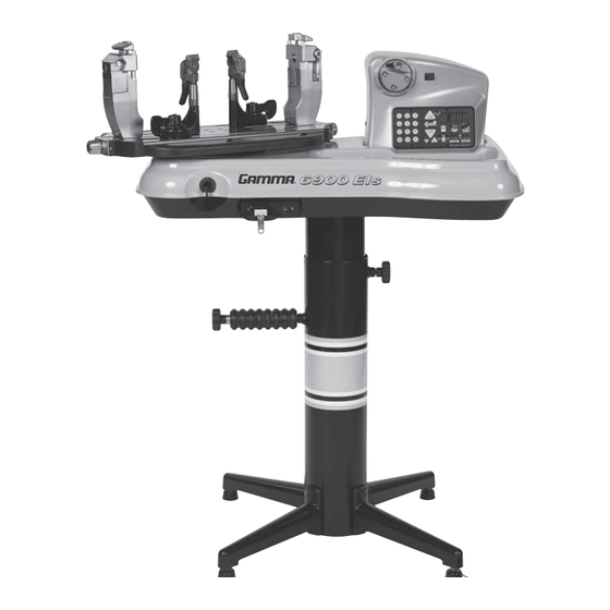
Page 3: Features
FEATURES MACHINE FEATURES Electronic Constant Pull Tensioner with 11.0 to 90.0 lbs Tension Range Digital Tension Setting with LED Display Professional Self-Centering Two Point Racquet Mounting Sys- tem- Accommodates All Racquets Parallel Jaw Rotating Gripper with Diamond Dust Coated Grip- ping Surfaces ... - Page 4 fl oor stand post and base legs. Please save the cartons and packing materials for possible shipments in the future. Gamma Sports cannot be responsible for machines that are not returned, shipped in their original, undamaged packaging.
- Page 5 ASSEMBLY INSTRUCTIONS Floor Stand Assembly The stringing machine uses a four leg fl oor stand design. The legs must be as- sembled to the lower column before use. Remove all parts from the shipping carton to confi rm that contents match the list of parts on Page 5.
- Page 6 ASSEMBLY INSTRUCTIONS Height Adjustment The height of the machine is adjustable from 39” to 46” in approximate 1” incre- ments. To change the height, remove the socket head cap screw from its current po- sition and place it in the appropriate hole to set the desired height of the machine.
- Page 7 ASSEMBLY INSTRUCTIONS Turntable and Mounting System Installation To install the turntable position the turntable over the turntable pin and align the bolts, located in the poly bag, with the holes in the fl ange. Secure them with the included allen wrench. String Clamp Installation The post of the string clamp and tube of the string clamp base are treated with grease to...
- Page 8 STRING REEL HOLDER INSTALLATION The string reel holder is an 8 mm rod with threads on both ends, and fl at surfaces machined on one end. Thread the end of the rod without the fl at surfaces into the threaded boss on the side of the lower column.
-
Page 9: Power Connection & Controls
POWER CONNECTION & CONTROLS Front Panel Features A - String Gripper B - Tension Switch C - Control Panel Back Panel Features A - Lighted Power Switch B - Foot Pedal Switch Receptacle C - A/C Power Cord Socket D - String Length Meter Socket Instructions for Power Connection and Controls CAUTION ! Before connecting to the power supply, check the voltage source that the machine is being connected to. - Page 10 CONTROL PANEL FUNCTIONS AND FEATURES Three Digit (XX.X) Tension Setting Dis- Single Digit (1-9) play or String Length Memory LED Display LED Display Memory Button - Indexes from 9 preset Tension Index Buttons - Changes tension settings that can be stored in tension setting in +/- 1.0 or +/- 0.1 Lb or memory.
- Page 11 MOUNTING THE FRAME Adjusting the Inner Racquet Supports The white racquet supports are adjustable to accommodate all racquets and provide maximum support to the racquet frame. Screw the pads up or down so they contact the frame at a maximum height without blocking the grommet holes. Mounting Stand Adjustment When mounting a racquet, adjust the Mounting Stands so that the white Racquet...
-
Page 12: Mounting The Frame
MOUNTING THE FRAME Special Throat Mounting For racquets with a bridge that is thinner than the rest of the frame or are tapered from head to throat you may need to mount the racquet with the shafts of the racquets supported by the white support pads as pictured. - Page 13 STRINGING THE FRAME Getting Started To begin stringing the main strings, thread the two ends of the string through the two center holes at the appropriate end of the frame and continue through the opposite center holes. Thread one end of the string through the adjacent grommet hole and pull excess by hand.
- Page 14 STRINGING THE FRAME To apply tension to a string, push the tension switch or the foot pedal. The string gripper will rotate and slowly apply tension to the string. When the set tension has been attained, the gripper will stop rotating and the display will fl...
-
Page 15: Additional Features
STRINGING THE FRAME Completing the String Job Once the fi nal cross string is tensioned and clamped, tie off at the appropriate hole speci- fi ed by the racquet manufacturer. Remove the frame from the mounting system by releasing the racquet holddowns and loosening the mounting stands. -
Page 16: String Length Meter
STRING LENGTH METER OPERATION To enable the String Length Meter (SLM) function, press the String Length button on the keypad. When the String Length but- ton is pressed, one of the LED indicators above “M” or “FT” will light up to indicate that the SLM function is enabled. -
Page 17: Pathfinder Awl
PATHFINDER AWL The machine includes the Pathfi nder string- ing awl which creates a pathway between or around strings to make inserting a string through blocked grommets easier and quicker. Insert the awl through the grommet hole in the same manner as for traditional awls. The Pathfi... - Page 18 Most tension calibrators (such as a Gamma Tension Calibrator) function by clamping off the string attached to one the end of the calibrator and applying tension to the string located on the opposite end of the calibrator.
-
Page 19: Maintenance & Adjustments
MAINTENANCE & ADJUSTMENTS Clamp Base Locking Nut Adjustment In the event the Locking Lever rotation is insuffi cient to ensure smooth operation of the clamp base, very minor adjustments to the Clamp Base Locking Nut can be made with the supplied 17mm socket and a hex wrench as a lever. -
Page 20: Troubleshooting Tips
MAINTENANCE & ADJUSTMENTS 2pt Hold Down Clamp Adjustment The 2pt hold down clamps have been adjusted at the factory. However, depending on the racquet frame thickness, the hold down clamp may require adjustment. Use a 3 mm hex wrench and turn the set screw clockwise to reduce the hold down clamp pressure and counter clockwise to increase the hold down clamp pressure. - Page 21 NOTES...
-
Page 22: Parts List
PARTS LIST PART # DESCRIPTION TOOLS & ACCESSORIES RUBBER FOOT* NEEDLE NOSE PLIERS* CAP SCREW- M8x30 BENT NOSE PLIERS* STAND BRAKE KNOB DIAGONAL CUTTERS* SHORT LEG 17MM SOCKET* FLAT HEAD SCREW- M8x25 SLM PADS* LEVELING FOOT HEX WRENCH SET* TT BOLTS* FOOT PEDAL SWITCH* STRING REEL HOLD BOLT A/C POWER CORD*... -
Page 23: Parts Drawing
PARTS DRAWING MRSGD MDCSC13 MQAC12... - Page 24 MMU2-81 (MG692-13) GAMMA SPORTS 200 Waterfront Drive Pittsburgh, Pennsylvania 15222 Phone: 800.333.0337 Fax: 412.323.0317 Visit our website at www.gammasports.com Copyright 2014 GAMMA Sports - All Rights Reserved...
Need help?
Do you have a question about the 6900 Els and is the answer not in the manual?
Questions and answers