Advertisement
Table of Contents
- 1 Table of Contents
- 2 Warranty
- 3 Features
- 4 Unpacking & Assembly Instructions
- 5 Power Connection & Controls
- 6 Control Panel Functions and Features
- 7 String Gripper Operation
- 8 Mounting the Frame
- 9 Stringing the Frame
- 10 String Length Meter
- 11 Additional Features
- 12 Pathfinder Awl
- 13 Maintenance & Adjustments
- 14 Troubleshooting Tips
- 15 Parts List
- 16 Parts Drawing
- Download this manual
Advertisement
Table of Contents

Related Manuals for Gamma 7900 Els


Summary of Contents for Gamma 7900 Els
- Page 1 7900 Els STRINGING MACHINE 2 PT SC MOUNTING OWNER’S MANUAL Issue 1 - June 2015...
-
Page 2: Table Of Contents
(excluding electrical parts and string clamps), and for a period of one (1) year from the date of purchase for all electrical parts and string clamps. Should any defects develop under normal use within the specifi ed time periods, GAMMA will at its option, repair or replace the defective EQUIPMENT provided it is returned to GAMMA prepaid at the purchaser’s expense. -
Page 3: Features
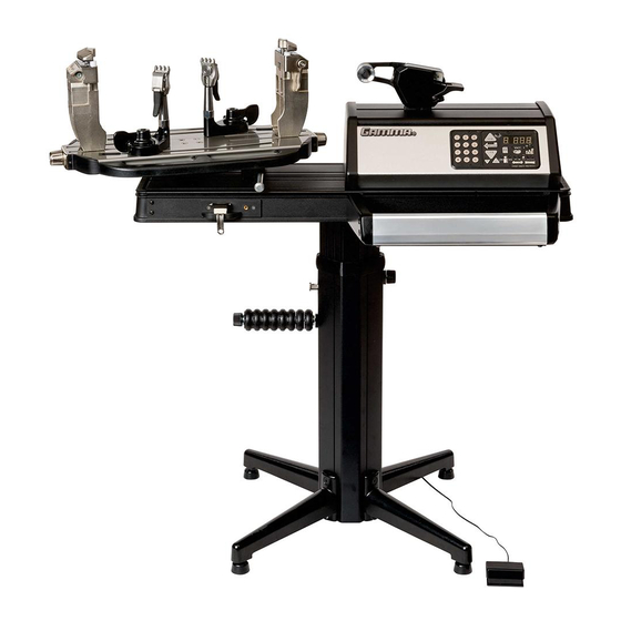
MACHINE FEATURES MACHINE FEATURES Electric Constant Pull Tensioner with 11.0 to 90.0 lbs Tension Range Digital Tension Setting with LED Display Quick Closing Linear String Gripper Professional Two Point Self Centering Racquet Mounting System- Accommodates All Racquets ... -
Page 4: Unpacking & Assembly Instructions
fl oor stand post and base legs. Please save the cartons and packing materials for possible shipments in the future. Gamma Sports cannot be responsible for machines that are not returned, shipped in their original, undamaged packaging. - Page 5 ASSEMBLY INSTRUCTIONS Floor Stand Leg Assembly The stringing machine uses a four leg fl oor stand design. The legs must be assembled to the Lower Column before use. Remove all parts from the shipping carton to confi rm that contents match the parts list. Align the holes in the Leg Flange with the matching holes in the Lower Column.
- Page 6 ASSEMBLY INSTRUCTIONS Attaching the Floor Stand to the Machine Base Refer to the instruction sheet provided with the fl oor stand for detailed instructions on which holes of the fl ange plate to use and align with the threaded inserts located in the slots on the underside of the machine base.
- Page 7 ASSEMBLY INSTRUCTIONS Tool Tray Installation The Tool Tray will be attached to the aluminum extruded machine base on the right hand side below the tensioner. To install the tool tray orient the tray at an angle and carefully insert the keyed tabs into the horizontal slot along the top edge of the base.
- Page 8 ASSEMBLY INSTRUCTIONS AC Power Adapter Storage Shelf The AC Power Adapter Storage Shelf pro- vides a means to secure and protect the power adapter by storing it safely under the machine base. This will reduce a potential tripping hazard as well as eliminate potential damage to the AC Power Supply if laying on the fl...
- Page 9 ASSEMBLY INSTRUCTIONS String Reel Installation The String Reel Holder pin is an 8 mm rod with threads on both ends and fl at surfaces machined on one end. Thread the end of the rod without the fl at surfaces into the threaded boss on the right side of the Lower Column.
- Page 10 ASSEMBLY INSTRUCTIONS Turntable and Mounting System Installation To install the Turntable position the Turntable over the turntable pin and align the holes in the turntable with the holes in the turntable pin. Insert the bolts through the holes in the turntable and turntable pin and tighten with an M6 hex wrench.
-
Page 11: Power Connection & Controls
POWER CONNECTION & CONTROLS Front Panel Features A - String Gripper B - Tension Lever Switch C - Control Panel with LED Display Back Panel Features D - Power Switch E - A/C Power Cord Socket F - Foot Pedal Switch Receptacle Instructions for Power Connection and Controls CAUTION ! Before connecting to the power supply, check the voltage source that the machine is being connected to. -
Page 12: Control Panel Functions And Features
CONTROL PANEL FEATURES Single Digit (1-9) Three Digit (XX.X) Tension Setting Memory LED Display Display or String Length LED Display 12 Button Keypad - Used to enter tension settings Tension Index Buttons - Changes Memory Button - Indexes from 9 preset tension setting in +/- 1.0 or +/- 0.1 Lb or tension settings that can be stored in Kg increments. -
Page 13: String Gripper Operation
STRING GRIPPER OPERATION String Gripper Operation To insert a string into the Quick Closing linear string gripper, wrap the string clockwise around the string guide and insert the string between the string gripper plates. Excessive slack in the string should be removed before applying tension. -
Page 14: Mounting The Frame
MOUNTING THE FRAME Mounting Stand Adjustment When mounting a racquet, adjust the Mounting Stands so that the white Racquet Supports on top of the Mounting Stands fi t inside the hoop of the racquet. Lower the racquet over the Racquet Supports and ad- just the Mounting Stands until the supports just make contact with the inside surface of the racquet at the head and throat. - Page 15 MOUNTING THE FRAME Special Throat Mounting Racquets with a bridge that is thinner than the rest of the frame or are tapered from head to throat require special mounting to ensure the frame is not damaged. The white Support Pads need to be moved from the inside of the racquet bridge to the throat of the racquet.
-
Page 16: Stringing The Frame
STRINGING THE FRAME String Clamp Operation The String Clamps are a dual action design where the String Clamp and Clamp Base operate independently of one another. To clamp a string, lift the String Clamp and place the string between the jaws and depress the String Clamp Lever to secure the string. - Page 17 STRINGING THE FRAME Pulling Tension Remove excessive slack in the string before applying tension. To apply tension to the main string, wrap the string clockwise around the String Guide to ensure that the proper tension will be applied to the string. Insert the string between the String Gripper Plates and apply tension to the string by pressing the Tension Lever Switch or the Foot Pedal Switch.
- Page 18 STRINGING THE FRAME Clamping the First Main String Secure the tensioned main string using the remaining fi xed clamp. Repeat the procedure for all of the remaining main strings and tie off at the appropriate holes following the racquet manufacturers specifi cations. This will determine the starting point for the cross strings.
-
Page 19: String Length Meter
STRING LENGTH METER OPERATION String Length Meter Press the String Length Meter (SLM) button to enable the SLM function and display the SLM screen. To change the measurement units from feet (FT) to Meters (M) press the SLM button to toggle between FT and M. String Length Meter (SLM) button To measure a length of string from a reel or set of string, insert the end of the string... -
Page 20: Additional Features
ADDITIONAL FEATURES Turntable Brake The Turntable may be locked in any position. To lock the Turntable Brake pull the brake lock pin OUT. To release the Turntable Brake push the brake lock pin IN. Storage Drawers There are two Storage Drawers located in the base of the machine. -
Page 21: Pathfinder Awl
PATHFINDER AWL The machine includes the Pathfi nder String- ing Awl which creates a pathway between or around strings to make inserting a string through blocked grommets easier and quicker. Insert the awl through the grommet hole in the same manner as for traditional awls. The Pathfi... -
Page 22: Maintenance & Adjustments
MAINTENANCE & ADJUSTMENTS Tension Calibration Pro- cedure During power up press the TEST button to enable the calibration mode. The display will show 22 lbs or 10 kgs. KG/LBS can be changed at any time by press- ing the LB/KG Button. Using a Tension Calibrator, apply tension to the calibrator and adjust the value on the display up or down to match the reading on the calibrator. - Page 23 MAINTENANCE & ADJUSTMENTS Adjusting the Clamp Base In the event the Clamp Base Locking Lever rotation is insuffi cient to ensure smooth operation of the Clamp Base, very minor adjustments to the Clamp Base Locking Nut can be made with a 17mm socket. Tighten or loosen the locking nut in very small incre- ments to provide more clamping pressure or running clearance as needed.
-
Page 24: Troubleshooting Tips
TROUBLESHOOTING TIPS PROBLEM SOLUTION String slips in clamps - Adjust gap between clamp jaws - Clean clamp jaws String slips in gripper - Adjust gripper jaw stop screw - Clean gripper jaws String clamp base slips on turntable - Clean bottom of clamp & top of turntable with alcohol - Adjust clamp base locking nut String tension too tight or too loose... - Page 25 NOTES...
-
Page 26: Parts List
PARTS LIST PART # DESCRIPTION PART # DESCRIPTION LEVELING FOOT 7900 ELS TENSIONER w24 KEY LED TT SCREWS* 79/89 TENSIONER CAP (R) STRING REEL HOLDER BOLT 79/89 TENSIONER CAP (L) STRING REEL HOLDER SPACER 79/89 BASE STRING REEL HOLDER KNOB... -
Page 27: Parts Drawing
PARTS SUMMARY MMSC13 MQAC12... - Page 28 MMAN-58 (MG792-10) GAMMA SPORTS 200 Waterfront Drive Pittsburgh, Pennsylvania 15222 Phone: 800.333.0337 Fax: 412.323.0317 Visit our website at www.gammasports.com Copyright 2015 GAMMA Sports - All Rights Reserved...
Need help?
Do you have a question about the 7900 Els and is the answer not in the manual?
Questions and answers