Advertisement
Advertisement
Table of Contents

Related Manuals for Gamma 6500 Els


Summary of Contents for Gamma 6500 Els
- Page 1 6500 Els STRINGING MACHINE 2 POINT MOUNTING OWNER'S MANUAL Issue 1 - July 2006...
- Page 2 (excluding electronic parts and string clamps), and for a period of one (1) year from the date of purchase for electronic parts and string clamps. Should any defects develop under normal use within the specified time periods, GAMMA will at its option, repair or replace the defective EQUIPMENT provided it is returned to GAMMA prepaid at the purchaser's expense.
-
Page 3: Features
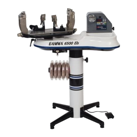
6500 Els KEY PRODUCT FEATURES Electric Constant Pull String Tensioner w/ Diamond Coated String Gripper (10-90 lbs tension range in 0.5 lbs increments) Control Panel w/ Calibration, Lbs/Kgs, Pulling Speed & String Length Functions String Reel Holder Electronic String Length Meter... - Page 4 The tools you will need to assemble the 6500 Els are provided with the machine. Due to the weight of the tensioner unit, you may need the assistance of someone to help lift the tensioner unit out of the carton.
-
Page 5: Assembly Instructions
ASSEMBLY INSTRUCTIONS Base Leg Assembly The stringing machine uses a four leg base design. The legs must be assembled to the support post before use. Remove the lower column support, the upper column support, four (4) legs, four (4) socket head cap screws and four (4) flat head cap screws from the small shipping carton. - Page 6 ASSEMBLY INSTRUCTIONS Stand Upper Post Installation Remove the four (4) button head cap screws from the base of the assembly. Stand Upper Post Installation (cont.) With the height adjustment cap screw on the upper post facing the left side of the tensioner, align the four (4) holes in the upper post flange with the holes in the tensioner base.
- Page 7 ASSEMBLY INSTRUCTIONS Installing the Turntable Remove the nuts from underneath of the turntable and leave the screws in position. Align the four (4) holes in the center of the turntable with the four (4) holes on the turntable pin. Tighten them securely with the 6mm allen wrench.
- Page 8 STRING REEL HOLDER INSTALLATION The string reel holder pin is an 8 mm rod with threads on both ends, and flat surfaces machined on one end. Thread the end of the pin without the flat surfaces into the threaded boss on the right side of the lower column support.
- Page 9 SLM FACE PLATE INSTALLATION Remove the tape covering the opening on the front side of the bottom cover to expose the string length meter. Position the face plate assembly over the opening in the bottom cover, and align the two countersunk end holes of the face plate with the threaded attachment holes in the front of the string length meter.
-
Page 10: Power Connections & Control
POWER CONNECTION AND CONTROLS Instructions for Power Connection (Refer to Figure 1) CAUTION ! Before connecting to the power supply, check the voltage supply switch setting located on the side panel as shown in Figure 1. To change from 115 volts service to 230 volt service simply slide the switch fully to the top or to the bottom until “115V”... - Page 11 CONTROL PANEL FUCTIONS AND FEATURES Lbs/Kgs Button - Changes tension display from Lbs to Kgs. Each press of the button toggles back and forth between Lbs and Kgs. Three digit (XX.X) LED Display - Speed Button - Changes pulling speed of winder Displays Tension Settings or String from Fast to Slow.
-
Page 12: String Length Meter Operation
STRING LENGTH METER OPERATION To enable the String Length Meter (SLM) function, press the String Length function key on the keypad. When the String Length button is pressed, one of the Red LED indicators below “M” or “FT” will light up to indicate that the SLM function is enabled. -
Page 13: Quick Action Clamp Operation
QUICK ACTION CLAMP OPERATION Clamp Head Operation To clamp a string, lift the clamp head and place the string between the jaws and de- press the clamp head lever to secure the string. The clamping pressure applied to the string should be adjusted to provide suffi- cient pressure to secure the string when subjected to the desired pulling tension. - Page 14 STRING GRIPPER OPERATION String Gripper Operation To insert the string in the split drum string gripper, wrap the free end of the string clock- wise around the gripper drum and position the string between the gripper jaws as shown in the illustration. The string must pass over the top half of the gripper before being placed between the diamond coated plates of the upper and...
-
Page 15: Mounting The Frame
MOUNTING THE FRAME Adjusting the Inner Racquet Supports The white racquet supports are adjustable to accommodate all racquets and provide maximum support to the racquet frame. Screw the the pads up or down so they contact the frame at a maxium height without blocking the grommet holes. Mounting Post Adjustment Place the racquet frame over the white racquet supports. -
Page 16: Stringing The Frame
MOUNTING THE FRAME Securing the Racquet Hold Down Depress the racquet hold down lever to secure the racquet frame. STRINGING THE FRAME Installing the Main Strings To begin stringing the main strings, insert the two ends of the string through the two center holes at the appropriate end of the frame and continue through the center holes on the opposite end of the racquet. - Page 17 PATHERFINDER AWL OPERATION The machine includes the Pathfinder string- ing awl which creates a pathway between or around strings to make inserting a string through tight grommets easier and quicker. Insert the awl through the grommet hole in the same manner as for traditional awls. The Pathfinder awl must be in the closed position before insertion.
-
Page 18: Tensioner Calibration
To adjust the calibration of the 6500 Els machine : 1 - Set the tension so the display reads 30.0 lbs and turn off the machine. - Page 19 CLEANING INSTRUCTIONS To thoroughly clean the diamond coated surfaces of the clamp heads, remove the adjustment knob screw to expose the inside surfaces of the clamps. Using the cleaning stone provided with your machine (you can also use a small tooth brush or a sharpening stone for knives), scrub the diamond coated plates until all debris is removed.
-
Page 20: Trouble Shooting Tips
If it is burned out, replace it with the spare fuse and replace the fuse holder in its socket. Supply power to the machine and check for proper operation. If problems persist, contact Gamma Sports Customer Service at 1-800-333- 0337 Gripper will not release string •... - Page 21 PARTS SUMMARY MQAC MDCSC MRSGD Inside Cover Inside Cover...
- Page 22 PARTS LIST PART# DESCRIPTION SPARE PARTS & TOOLS (NOT CAP SCREW - M8 x 30 PICTURED) GRIPPER CAP SCREW SET AC POWER CORD PART# DESCRIPTION FUSE HOLDER CAP NEEDLE NOSE PLIERS FUSE BENT NOSE PLIERS LOCKING KNOB SCREW CUTTING PLIERS SHORT LEG TT BRAKE PAD FLAT HEAD CAP SCREW-M8 x 25...
Need help?
Do you have a question about the 6500 Els and is the answer not in the manual?
Questions and answers