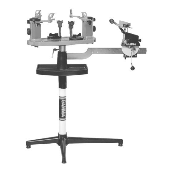
Gamma 6004 Owner's Manual
6 point mounting
Hide thumbs
Also See for 6004:
- Owner's manual (20 pages) ,
- Owner's manual (20 pages) ,
- Owner's manual (24 pages)

Subscribe to Our Youtube Channel
Related Manuals for Gamma 6004


Summary of Contents for Gamma 6004
- Page 1 6004 STRINGING MACHINE 6 POINT MOUNTING OWNER'S MANUAL Issue 5 - June 2006 Provided by www.gssalliance.com Copyright 2001 GAMMA Sports - All Rights Reserved...
- Page 2 To return defective EQUIPMENT, a return authorization (RA#) must be obtained from GAMMA customer service. The RA# must be marked on the outside of the shipping carton being returned. All returns must be shipped prepaid by the customer to GAMMA. Please retain the original shipping carton and packing materials for any future shipments.
- Page 3 GAMMA 6004 MACHINE FEATURES MACHINE FEATURES Manual Spring Tensioner Diamond Coated String Gripper Tension Range: 11lbs. - 89lbs. Professional Six Point Self-Centering “Suspension Mount” Racquet Mounting System - Accomodates All Racquets Without Adapters Switch Action Cam Lock Dual Action Metal String Clamps...
- Page 4 ASSEMBLY INSTRUCTIONS Base Leg Assembly The GAMMA 6004 stringing machine uses a four leg base design. The legs must be assembled to the support post before use. Remove the lower column support from the carton. Align the holes in the leg flange with the matching holes in the lower column support post.
- Page 5 ASSEMBLY INSTRUCTIONS Bellows Installation The bellows assembly is supplied in two pieces and should be assembled as follows. Place the bellows section with the flange over the upper support column with the flange on the top. Place the remaining bel- lows over the upper support column and mate it with the flange on the lower bellows.
- Page 6 ASSEMBLY INSTRUCTIONS Turntable Installation Remove the nuts from underneath of the turntable. Position the 4 screws over the flange of the turntable pin. Engaging the turntable brake helps position the screws. Attach the turntable to the turntable pin flange using the 4 included M6 cap screws. Tighten securely.
- Page 7 ASSEMBLY INSTRUCTIONS Clamp Head Installation The post of the string clamp head and the tube of the string clamp base are treated with grease to provide protection against corrosion during shipping. Remove any excessive grease with a clean cloth prior to use. The post and tube may also be cleaned with isopropyl alcohol.
- Page 8 Travel Stop yond the opposite surface of the tensioner bar. Setting the Gripper Jaw Spacing The gripper jaws of the 6004 tensioner are adjustable to accomodate varying string gauges. If the string slips through the gripper jaws while pulling tension, rotate the gripper jaw adjustment screw counter-clockwise.
- Page 9 MOUNTING THE FRAME Securing the Shoulder Supports Secure the racquet frame with the shoulder supports by rotating the large adjustment knobs on the outside of the support post assemblies clockwise. Adjust the supports until firm contact is made between the shoul- der supports and the frame.
- Page 10 STRINGING THE FRAME Setting Tension The spring tensioner utilizes a rotary adjust- ing knob along with a linear tension scale to indicate the tension setting. The scale is divided into 3 lb increments and each 1/3 turn of the tension knob changes tension by 1 lb. To set the desired tension, rotate the tension knob and align the mark on the spring guide with the desired tension setting on the scale.
- Page 11 STRINGING THE FRAME Pulling Tension Wrap the loose section of string once around the roller and insert the string between the diamoind dust coated string gripper plates. Pull the string perpendicular to the gripper plates while slowly rotating the tensioner crank clockwise until the brake lever pops out of the latching block.
- Page 12 PATHFINDER AWL The GAMMA 6004 includes the Pathfinder stringing awl which creates a pathway be- tween or around strings and through tight grommets. Insert the awl through the grommet hole in the same manner as for traditional awls. The Pathfinder awl must be closed before inser- tion.
- Page 13 MAINTENANCE & ADJUSTMENTS Tension Calibration Procedure Step 1 Set the tension to 60 lbs. as indicated by the linear scale and rotary knob. Place the string on one end of a tension calibrator into a string clamp and secure. Place string lo- cated on the other end of the calibrator into the string tensioner and apply tension.
- Page 14 MAINTENANCE & ADJUSTMENTS Adjusting the Tensioner Brake Step 1 After stringing many racquets, the brake of the tensioner may need to be adjusted. With the brake lever engaged, loosen the lock bolt located on the back side of the tensioner frame with the 4mm hex wrench. Note: The lock bolt should only be loosened enough to be turned by hand and must not be removed completely.
- Page 15 MAINTENANCE & ADJUSTMENTS String Clamp Adjustment The string clamps will need minor adjustments according to string type, construction, and gauge. To adjust the gap (clamping pressure) between the clamp jaws, insert the string through the racquet as if you were beginning the main strings. Clamp the string and pull tension.
- Page 16 MAINTENANCE & ADJUSTMENTS Turntable Brake Pad Replacement Loosen the four set screws located at the top of the turntable tube until the turntable and turntable flanged pin can be lifted from the support tube. Insert the 2.5 mm L-shaped wrench into the flat head screw located on the inner side of the brake pad and the end of the brake lever bolt.
- Page 17 TROUBLESHOOTING TIPS PROBLEM SOLUTION String slips in clamps - Adjust gap between jaws - Clean clamp jaws String slips in gripper - Clean gripper jaws - Adjust Gripper Jaw Stop Screw String clamp base slips on turntable. - Adjust Base Locking Levers - Clean Turntable Clamp Glide Rails Tensioner slips on Tensioner Bar - Adjust tensioner brake lever...
- Page 18 COMPONENT IDENTIFICATION MDCSC MSAC 104A MFSPP MMSPP MMSPP MMSSA MFSPP...
- Page 19 PARTS LIST TOOLS AND PART # DESCRIPTION ACCESSORIES CAP SCREW - M8x30 BOX WRENCH - 10MM 104A TENSIONER ASSEMBLY NEEDLE NOSE PLIERS TENSIONER TRACK BENT NOSE PLIERS TOOL TRAY CUTTING PLIERS STAND LEG - LONG LONG HEX WRENCH SET - 9 PC. STAND LEG - SHORT MBFC BADMINTON FLYING CLAMP...
Need help?
Do you have a question about the 6004 and is the answer not in the manual?
Questions and answers