Gamma 6004 Owner's Manual
Hide thumbs
Also See for 6004:
- Owner's manual (20 pages) ,
- Owner's manual (24 pages) ,
- Owner's manual (19 pages)
Table of Contents
Advertisement
Advertisement
Table of Contents

Related Manuals for Gamma 6004


Summary of Contents for Gamma 6004
- Page 1 WNER'S MANU Issue 3 - December 14, 2000 Issue 3 - December 14, 2000 Issue 3 - December 14, 2000 Issue 3 - December 14, 2000 Issue 3 - December 14, 2000 Copyright 2000 GAMMA Sports - All Rights Reserved...
-
Page 2: Table Of Contents
(5) years from the date of original purchase for mechanical parts (excluding string clamps), and for a period of one (1) year from the date of purchase for string clamps. Should any defects develop under normal use within the specified time periods, GAMMA will at its option, repair or replace the defective EQUIPMENT provided it is returned to GAMMA prepaid at the purchaser's expense. -
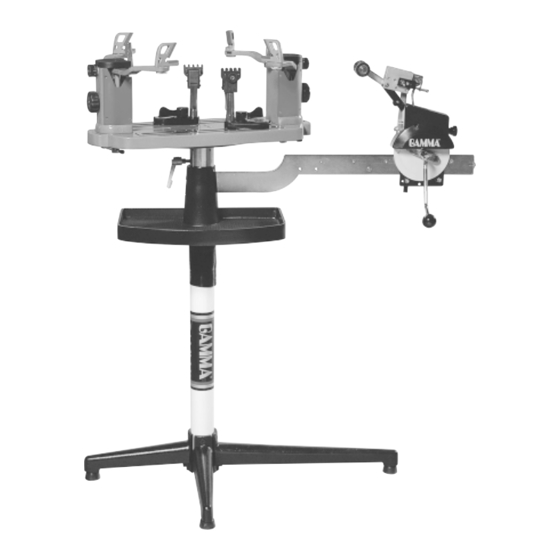
Page 3: Features
MACHINE FEATURES ! Manual Spring Tensioner ! Diamond Coated String Gripper ! Tension Range: 11lbs. - 89lbs. ! 6 Point Suspension Mounting System ( 10 Point Support ) CAM-LOCK Dual Action Composite String Clamps w/ Diamond Coating ! Full 360 Degree Turntable Rotation ! Precision Bearing Mounted Turntable ! Large Convenient 141 sq. -
Page 4: Assembly Instructions
ASSEMBLY INSTRUCTIONS Base Leg Assembly The GAMMA 6004 stringing machine uses a four leg base design. The legs must be assembled to the support post before use. Remove the lower column support from the carton. Align the holes in the leg flange with the matching holes in the lower column support post. - Page 5 ASSEMBLY INSTRUCTIONS Bellows Installation The bellows assembly is supplied in two pieces and should be assembled as follows. Place the bellows section with the flange over the upper support column with the flange on the top. Place the remaining bellows over the upper support column and mate it with the flange on the lower bellows.
- Page 6 ASSEMBLY INSTRUCTIONS Turntable Installation Position the recess in the underside of the turntable over the flange of the turntable pin. Attach the turntable to the turntable pin flange using the included 4 - M6 cap screws. Tighten securely. Frame Support Post Installation The support post assemblies are precision aligned at the factory and are marked for proper installation on the turntable.
- Page 7 ASSEMBLY INSTRUCTIONS Clamp Head Installation The post of the string clamp head and the tube of the string clamp base are treated with grease to provide protection against corrosion during shipping. Remove any excessive grease with a clean cloth prior to use. The post and tube may also be cleaned with isopropyl alcohol.
- Page 8 Travel Stop Setting the Gripper Jaw Spacing The gripper jaws of the 6004 tensioner are adjustable to accomodate varying string gauges. If the string slips through the gripper jaws while pulling tension, rotate the gripper jaw adjustment screw counter- clockwise.
-
Page 9: Mounting The Frame
MOUNTING THE FRAME Height Adjustment The turntable height of the GAMMA 6004 can be ad- justed to suit the stringer. To adjust, loosen the two set screws on the lower column support post below the bellows assembly. Adjust the amount of engagement between the upper and lower column supports until the desired height is attained. - Page 10 MOUNTING THE FRAME Support Slide Adjustment Once the frame support posts are secured, lightly tighten the support slides by turning the knobs on the outside of the slides clockwise. Adjust the slides in equal incre- ments until slight resistance is felt. Apply a final adjustment to all racquet support points until the racquet is firmly secured in the mounting system.
-
Page 11: Stringing The Frame
STRINGING THE FRAME Setting Tension The GAMMA 6004 utilizes a rotary adjusting knob along with a linear tension scale to indicate the tension setting. The scale is divided into 3 lb increments and each 1/3 turn of the tension knob changes tension by 1 lb. To set... - Page 12 STRINGING THE FRAME Pulling Tension Wrap the loose section of string once around the roller and insert the string between the diamoind dust coated string gripper plates. Pull the string perpendicular to the gripper plates while slowly rotating the tensioner crank clockwise until the brake lever pops out of the latching block.
-
Page 13: Pathfinder Awl
PATHFINDER AWL The GAMMA 6004 includes the new Pathfinder string- ing awl which creates a pathway between or around strings and through tight grommets. Insert the awl through the grommet hole in the same manner as for traditional awls. The Pathfinder awl must be closed before insertion. -
Page 14: Maintenance And Adjustments
MAINTENANCE and ADJUSTMENTS Tension Calibration Procedure Step 1 Set the tension to 60 lbs. as indicated by the linear scale and rotary knob. Place the string on one end of a tension calibrator into a string clamp and secure. Place string located on the other end of the calibrator into the string tensioner and apply tension. - Page 15 MAINTENANCE and ADJUSTMENTS Adjusting the Tensioner Brake Step 1 After stringing many racquets, the brake of the tensioner may need to be adjusted. With the brake lever engaged, loosen the lock bolt located on the back side of the tensioner frame with the 4mm hex wrench.
- Page 16 MAINTENANCE and ADJUSTMENTS Cam-Lock Cam-Lock Clamps will need minor adjustments Cam-Lock The Cam-Lock Cam-Lock according to what string type, construction, and gauge you are using. To adjust the gap (clamping pressure) between the clamp jaws, insert the string through the racquet as if you were beginning the main strings.
- Page 17 MAINTENANCE and ADJUSTMENTS Turntable Brake Pad Replacement Loosen the four set screws located at the top of the turntable tube until the turntable and turntable flanged pin can be lifted from the support tube. Insert the 2.5 mm L-shaped wrench into the flat head screw located on the inner side of the brake pad and the end of the brake lever bolt.
-
Page 18: Care And Cleaning
TROUBLESHOOTING TIPS PROBLEM SOLUTION String slips in clamps - Adjust gap between jaws - Clean clamp jaws String slips in gripper - Clean gripper jaws - Adjust Gripper Jaw Stop Screw String clamp base slips on turntable. - Adjust Base Locking Levers - Clean Turntable Clamp Glide Rails Tensioner slips on Tensioner Bar - Adjust tensioner brake lever... -
Page 19: Component Identification
COMPONENT IDENTIFICATION 104A 122A... - Page 20 PARTS LIST PART # DESCRIPTION PART # DESCRIPTION CAP SCREW - M8x30 TURNTABLE BRAKE LEVER WASHER - M8 TURNTABLE BRAKE PAD POST LOCK LEVER TT. BRAKE PAD SCREW WASHER - M10 FLANGED TURNTABLE PIN FRAME SUPPORT - TENNIS TT. BRAKE COLLAR FRAME SUPPORT - BAD.
Need help?
Do you have a question about the 6004 and is the answer not in the manual?
Questions and answers