Gamma 5800 Els Owner's Manual
6 point mounting
Hide thumbs
Also See for 5800 Els:
- Owner's manual (24 pages) ,
- Owner's manual (32 pages) ,
- Owner's manual (32 pages)
Advertisement
Advertisement
Table of Contents

Related Manuals for Gamma 5800 Els


Summary of Contents for Gamma 5800 Els
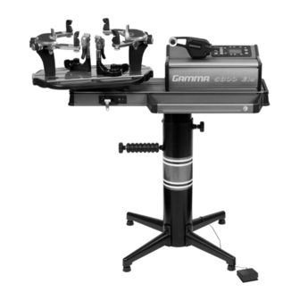
- Page 1 5800 Els STRINGING MACHINE 6 POINT MOUNTING OWNER'S MANUAL Issue 3 - January 2009...
- Page 2 (1) year from the date of purchase for all electrical parts and string clamps. Should any defects develop under normal use within the specified time periods, GAMMA will at its option, repair or replace the defective EQUIPMENT provided it is returned to GAMMA prepaid at the purchaser's expense.
-
Page 3: Features
FEATURES MACHINE FEATURES Electric Constant Pull Tensioner w/ 11 lbs. to 89 lbs. Tension Range Digital Tension Setting Display Professional Six Point “Quick Mount” Racquet Mounting System- Accomodates All Racquets Without Adapters Parallel Jaw Linear Gripper w/ Diamond Dust Coated Gripping Surfaces Professional Dual Action, Rotating, Diamond Dust Coated, Fixed String Clamps... - Page 4 Please save the cartons and packing materials for possible shipments in the future. Gamma Sports cannot be responsible for machines that are not returned, shipped in their original, undamaged packaging. The tools you will need to assemble the machine are provided with the machine.
- Page 5 ASSEMBLY INSTRUCTIONS Base Leg Assembly The stringing machine uses a four leg floor stand design. The legs must be assembled to the lower column before use. Remove all parts from the shipping carton to confirm that contents match the list of parts on Page 3. Base Leg Assembly (Cont.) Align the holes in the leg flange with the matching holes in the lower column.
- Page 6 ASSEMBLY INSTRUCTIONS Height Adjustment The height of the machine is adjustable from 39” to 46” in approximate 1” increments. To change the height, remove the socket head cap screw from its current position and place it in the appropriate hole to set the desired height of the machine.
- Page 7 STRING REEL HOLDER INSTALLATION The string reel holder pin is an 8 mm rod with threads on both ends, and flat surfaces machined on one end. Thread the end of the pin without the flat surfaces into the threaded boss on the right side of the lower column. Using the M6 open end wrench positioned on the flat surfaces, securely tighten the pin to the lower column.
- Page 8 ASSEMBLY INSTRUCTIONS Turntable and Mounting System In- stallation To install the turntable remove the four nuts underneath holding the mounting bolts in place. Position the turntable over the turn- table pin and align the bolts with the holes in the flange. Secure them with the included allen wrench.
-
Page 9: Power Connection & Controls
POWER CONNECTION & CONTROLS Front Panel Features A - String Gripper B - Tension Button C - Control Panel D - L.E.D. Tension Display Back Panel Features Lighted Power Switch A/C Power Cord Socket Foot Pedal Switch Receptacle String Length Meter Receptacle Instructions for Power Connection and Controls CAUTION ! Before connecting to the power supply, check the voltage source that the machine is being connected to. - Page 10 CONTROL PANEL FUNCTIONS AND FEATURES Three Digit (XX.X) Tension Setting Display Single Digit (1-9) or String Length LED Memory LED Display Display Tension Index Buttons - Changes Memory Button - Indexes from 9 preset tension setting in +/- 1.0 or +/- 0.1 Lb or tension settings that can be stored in Kg increments.
- Page 11 STRING GRIPPER OPERATION String Gripper Operation To insert a string into the linear string gripper, wrap the string clockwise around the roller guide and insert the string between the diamond dust coated string gripper plates. Excessive slack in the string should be removed before applying tension.
-
Page 12: Mounting The Frame
STRING CLAMPS String Clamp Operation The string c lamps are a dual action design where the string clamp and clamp base operate independently of one another. To clamp a string, lift the clamp head and place the string between the jaws and depress the string clamp lever to secure the string. - Page 13 MOUNTING THE FRAME Tightening the Frame Supports Tighten the Frame Support Slides by turning the adjustment knob clockwise until snug against the racquet frame and slight resis- tance is felt. Caution: Overtightening the Center Sup- ports will stretch the head of the racquet and could cause racquet damage.
-
Page 14: Stringing The Frame
STRINGING THE FRAME Getting Started To begin stringing the main strings, thread the two ends of the string through the two center holes at the appropriate end of the frame and continue through the opposite center holes. Thread one end of the string through the adjacent grommet hole and pull excess by hand. - Page 15 STRINGING THE FRAME Clamping the First Main String Secure the tensioned main string using the remaining fixed clamp. Repeat the proce- dure for all of the remaining main strings and tie off following the racquet manufacturers recommendations. Follow the manufacturer's recommended stringing pattern for one or two piece string- ing.
-
Page 16: String Length Meter Operation
STRING LENGTH METER OPERATION To enable the String Length Meter (SLM) function, press the String Length button on the keypad. When the String Length button is pressed, one of the LED indicators above “M” or “FT” will light up to indicate that the SLM function is enabled. -
Page 17: Additional Features
ADDITIONAL FEATURES Turntable Brake The turntable may be locked in any position. Flip the lever to the right to lock the turntable brake and flip the lever to the left to release the turntable brake. Storage Drawers There are two storage drawers located in the base of the machine. - Page 18 PATHFINDER AWL The machine includes the Pathfinder string- ing awl which creates a pathway between or around strings to make inserting a string through tight grommets easier and quicker. Insert the awl through the grommet hole in the same manner as for traditional awls. The Pathfinder awl must be in the closed position before insertion.
- Page 19 Most tension calibrators (such as a Gamma Tension Calibrator) function by clamping off the string attached to one the end of the calibrator and applying tension to the string located on the opposite end of the calibrator.
- Page 20 MAINTENANCE & ADJUSTMENTS Quick Action Clamp Base Removal Quick Action clamp bases can be removed from the turntable for maintenance or clean- ing by removing clamp stop located at the end of the slot in the turntable. To remove the clamp stop, remove the two screws holding the clamp stop in place from the underside of the turntable.
-
Page 21: Troubleshooting Tips
TROUBLESHOOTING TIPS PROBLEM SOLUTION String slips in clamps - Adjust gap between clamp jaws - Clean clamp jaws String slips in gripper - Adjust gripper jaws spacing - Clean gripper jaws String clamp base slips on turntable - Adjust clamp base Electrical system does not function - Check power source - Check power cord connection... -
Page 22: Pathfinder Awl
PARTS LIST PART# DESCRIPTION PART # DESCRIPTION CAP SCREW- M8 STRING LENGTH METER WASHER- M8 RUBBER FOOT WASHER- M10 BRAKE RING FRAME SUPP SLIDE BRAKE BOX (ES) STAND BRAKE KNOB LARGE DRAWER SHORT LEG SMALL DRAWER FLAT HEAD SCREW (M8X25) FOOT PEDAL SWITCH LEVELING FOOT DIECAST LINEAR GRIPPER... - Page 23 PARTS SUMMARY MMSPP 148R MDCSC MFSPP 146A MQAC MFSPP MMSPP MMSSA...
- Page 24 GAMMA SPORTS 200 Waterfront Drive Pittsburgh, Pennsylvania 15222 Phone: 800.333.0337 Fax: 412.323.0317 Visit our website at www.gammasports.com Copyright 2009 GAMMA Sports - All Rights Reserved...
Need help?
Do you have a question about the 5800 Els and is the answer not in the manual?
Questions and answers