Table of Contents
Advertisement
Advertisement
Table of Contents

Related Manuals for Keysight 33210A


Summary of Contents for Keysight 33210A
- Page 1 Keysight 33210A 10 MHz Function/Arbitrary Waveform Generator Service Guide...
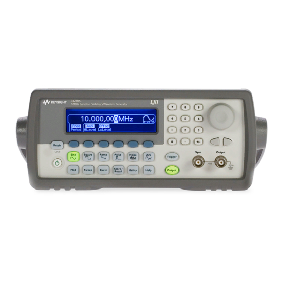
- Page 4 Keysight 33210A at a Glance The Keysight Technologies 33210A is a 10 MHz synthesized function generator with built-in arbitrary waveform and pulse capabilities. Its combination of bench-top and system features makes this function generator a versatile solution for your testing requirements now and in the future.
- Page 5 The Front Panel at a Glance 9 Manual Trigger Key (used for 1 Graph Mode/ Local Key 2 On/Off Switch Sweep and Burst only) 3 Modulation/Sweep/Burst Keys 10 Output Enable/Disable Key 4 State Storage Menu Key 11 Knob 5 Utility Menu Key 12 Cursor Keys 6 Help Menu Key 13 Sync Connector...
- Page 6 The Front-Panel Display at a Glance Menu Mode Output Mode Trigger Information Units Status Information Display Numeric Icon Readout Softkey Labels Graph Mode To enter or exit the Graph Mode, press the key. Parameter Parameter Name Value Signal Ground In Graph Mode, only one parameter label is displayed for each key at one time.
- Page 7 Front-Panel Number Entry You can enter numbers from the front-panel using one of two methods. Use the knob and cursor keys to modify the displayed number. 1. Use the keys below the knob to move the cursor left or right. 2.
- Page 8 The Rear Panel at a Glance 1 External 10 MHz Reference Input Terminal 5 USB Interface Connector (Option 001 only). 6 LAN Interface Connector 2 Internal 10 MHz Reference Output Terminal 7 GPIB Interface Connector (Option 001 only). 8 Chassis Ground 3 External Modulation Input Terminal 4 Input: External Trigger/Burst Gate Output: Trigger Output...
- Page 9 Backdating Chapter 8 describes the differences between this manual and older issues of this manual. You can contact Keysight Technologies at one of the following telephone numbers for warranty, service, or technical support information. In the United States: (800) 829-4444...
-
Page 11: Table Of Contents
To Unsecure and Secure for Calibration 41 To Store the Instrument State 44 To Configure the Remote Interface 45 Chapter 4 Calibration Procedures 51 Keysight Technologies Calibration Services 53 Calibration Interval 53 Adjustment is Recommended 53 Time Required for Calibration 54... - Page 12 +10 dB Range Flatness Verification 67 +20 dB Range Flatness Verification 69 Calibration Security 71 Calibration Message 73 Calibration Count 73 General Calibration/Adjustment Procedure 74 Aborting a Calibration in Progress 75 Sequence of Adjustments 75 Self-Test 76 Frequency (Internal Timebase) Adjustment 77 Internal ADC Adjustment/Self Calibration 78 Output Impedance Adjustment 79 AC Amplitude (high-impedance) Adjustment 81...
-
Page 13: Chapter 1 Specifications
Specifications... - Page 14 Chapter 1 Specifications Keysight 33210A Function / Arbitrary Waveform Generator Waveforms Square Frequency: 1 mHz to 10 MHz, Standard: Sine, Square, Ramp, 1 mHz resolution Triangle, Pulse, Noise, Rise/Fall Time: 20 ns Overshoot: < 2% Built-in Arbitrary (Option 002 Variable Duty Cycle:...
- Page 15 Chapter 1 Specifications Keysight 33210A Function / Arbitrary Waveform Generator Common Characteristics Phase Offset: Range: +360 to -360 degrees Frequency Resolution: 0.001 degrees Accuracy: 20 ns Accuracy 90 days: ± (10 ppm + 3 pHz) 1 year: ± (20 ppm + 3 pHz)
- Page 16 Chapter 1 Specifications Keysight 33210A Function / Arbitrary Waveform Generator Sweep Programming Times (typical) Waveforms: Sine, Square, Ramp Configuration Times Type: Linear or Logarithmic USB 2.0 LAN (VXI-11) GPIB Direction: Up or Down Function 120 ms 120 ms 120 ms...
- Page 17 Keysight 33210A Function / Arbitrary Waveform Generator Note: Specifications are subject to change General without notice. For the latest specifications, go to the Keysight 33210A product page and Power Supply: CAT II 100 to 240 V find the 33210A Datasheet.
- Page 18 Chapter 1 Specifications Keysight 33210A Function / Arbitrary Waveform Generator Product Dimensions All dimensions are shown in millimeters.
-
Page 19: Chapter 2 Quick Start
Quick Start... - Page 20 Quick Start One of the first things you will want to do with your function generator is to become acquainted with the front panel. We have written the exercises in this chapter to prepare the instrument for use and help you get familiar with some of its front-panel operations.
-
Page 21: To Prepare The Function Generator For Use
• Keysight Automation-Ready CD (Keysight IO Libraries Suite). • USB 2.0 cable. Note: All of the 33210A product documentation is provided on the Keysight 33210A Product Reference CD that comes with the product, and is also available on the Web at www.keysight.com/find/33210A. Printed (hardcopy) manuals are available as an extra cost option. -
Page 22: To Adjust The Carrying Handle
Chapter 2 Quick Start To Adjust the Carrying Handle To Adjust the Carrying Handle To adjust the position, grasp the handle by the sides and pull outward. Then, rotate the handle to the desired position. Retracted Carrying Position Extended... -
Page 23: To Set The Output Frequency
Chapter 2 Quick Start To Set the Output Frequency To Set the Output Frequency At power-on, the function generator outputs a sine wave at 1 kHz with an amplitude of 100 mV peak-to-peak (into a 50Ω termination). The following steps show you how to change the frequency to 1.2 MHz. 1 Press the “Freq”... - Page 24 Chapter 2 Quick Start To Set the Output Amplitude To Set the Output Amplitude At power-on, the function generator outputs a sine wave with an amplitude of 100 mV peak-to-peak (into a 50Ω termination). The following steps show you how to change the amplitude to 50 mVrms. 1 Press the “Ampl”...
-
Page 25: To Set The Output Amplitude 22
Chapter 2 Quick Start To Set the Output Amplitude You can easily convert the displayed amplitude from one unit to another. For example, the following steps show you how to convert the amplitude from Vrms to Vpp. 4 Enter the numeric entry mode. Press the key to enter the numeric entry mode. -
Page 26: To Set A Dc Offset Voltage
Chapter 2 Quick Start To Set a DC Offset Voltage To Set a DC Offset Voltage At power-on, the function generator outputs a sine wave with a dc offset of 0 volts (into a 50Ω termination). The following steps show you how to change the offset to –1.5 mVdc. -
Page 27: To Set The High-Level And Low-Level Values
Chapter 2 Quick Start To Set the High-Level and Low-Level Values To Set the High-Level and Low-Level Values You can specify a signal by setting its amplitude and dc offset values, as described previously. Another way to set the limits of a signal is to specify its high-level (maximum) and low-level (minimum) values. -
Page 28: To Select "Dc Volts
Chapter 2 Quick Start To Select “DC Volts” To Select “DC Volts” You can select the "DC Volts" feature from the “Utility” menu, and then set a constant dc voltage as an "Offset" value. Let's set "DC Volts" = 1.0 Vdc. -
Page 29: To Set The Duty Cycle Of A Square Wave
Chapter 2 Quick Start To Set the Duty Cycle of a Square Wave To Set the Duty Cycle of a Square Wave At power-on, the duty cycle for square waves is 50%. You can adjust the duty cycle from 20% to 80% for output frequencies up to 5 MHz. The following steps show you how to change the duty cycle to 30%. -
Page 30: To Configure A Pulse Waveform
Chapter 2 Quick Start To Configure a Pulse Waveform To Configure a Pulse Waveform You can configure the function generator to output a pulse waveform with variable pulse width and edge time. The following steps show you how to configure a 500 ms pulse waveform with a pulse width of 10 ms and edge times of 50 ns. -
Page 31: To View A Waveform Graph
Chapter 2 Quick Start To View a Waveform Graph To View a Waveform Graph In the Graph Mode, you can view a graphical representation of the current waveform parameters. The softkeys are listed in the same order as in the normal display mode, and they perform the same functions. However, only one label (for example, Freq or Period) is displayed for each softkey at one time. -
Page 32: To Output A Stored Arbitrary Waveform
To Output a Stored Arbitrary Waveform To Output a Stored Arbitrary Waveform Note: Arbitrary waveforms are optionally available with the 33210A (Option 002). To upgrade your 33210A to include arbitrary waveform functionality, go to www.keysight.com/find/33210A. There are five built-in arbitrary waveforms stored in non-volatile memory. -
Page 33: To Use The Built-In Help System
Chapter 2 Quick Start To Use the Built-In Help System To Use the Built-In Help System The built-in help system is designed to provide context-sensitive assistance on any front-panel key or menu softkey. A list of help topics is also available to assist you with several front-panel operations. 1 View the help information for a function key. - Page 34 Chapter 2 Quick Start To Use the Built-In Help System 3 View the list of help topics. Press the key to view the list of available help topics. To scroll through the list, press the ↑ or ↓ softkey or rotate the knob. Select the third topic “Get HELP on any key”...
-
Page 35: To Rack Mount The Function Generator
To Rack Mount the Function Generator To Rack Mount the Function Generator You can mount the Keysight 33210A in a standard 19-inch rack cabinet using one of two optional kits available. Instructions and mounting hardware are included with each rack-mounting kit. Any Keysight System II instrument of the same size can be rack-mounted beside the Keysight 33210A. - Page 36 Chapter 2 Quick Start To Rack Mount the Function Generator To rack mount a single instrument, order adapter kit 5063-9240. To rack mount two instruments side-by-side, order lock-link kit 5061-8769 and flange kit 5063-9212. Be sure to use the support rails in the rack cabinet. In order to prevent overheating, do not block the flow of air into or out of the instrument.
-
Page 37: Chapter 3 Front-Panel Menu Operation
Front-Panel Menu Operation... - Page 38 It does, however, give you an overview of the front- panel menus and many front-panel operations. Refer to the Keysight 33210A User’s Guide for a complete discussion of the function generator’s capabilities and operation. • Front-Panel Menu Reference, on page 37 •...
-
Page 39: Front-Panel Menu Reference
Chapter 3 Front-Panel Menu Operation Front-Panel Menu Reference Front-Panel Menu Reference This section gives an overview of the front-panel menus. The remainder of this chapter contains examples of using the front-panel menus. Configure the modulation parameters for AM, FM, and PWM. •... - Page 40 • How to create an arbitrary waveform. • How to reset the instrument to its default state. • How to view a waveform in the Graph Mode. • How to synchronize multiple instruments. • How to obtain Keysight Technical Support.
-
Page 41: To Select The Output Termination
To Select the Output Termination To Select the Output Termination The Keysight 33210A has a fixed series output impedance of 50 ohms to the front-panel Output connector. If the actual load impedance is different than the value specified, the displayed amplitude and offset levels will be incorrect. -
Page 42: To Read The Calibration Information
Chapter 3 Front-Panel Menu Operation To Read the Calibration Information To Read the Calibration Information You can access the instrument’s calibration memory to read the calibration count and calibration message. Calibration Count You can query the instrument to determine how many calibrations have been performed. -
Page 43: To Unsecure And Secure For Calibration
Chapter 3 Front-Panel Menu Operation To Unsecure and Secure for Calibration To Unsecure and Secure for Calibration This feature allows you to enter a security code to prevent accidental or unauthorized adjustments of the instrument. When you first receive your instrument, it is secured. Before you can adjust the instrument, you must unsecure it by entering the correct security code. - Page 44 Chapter 3 Front-Panel Menu Operation To Unsecure and Secure for Calibration To Unsecure for Calibration 1 Select the Secure Code interface. Press and then select the Test/Cal softkey. 2 Enter the Secure Code. Use the knob to change the displayed character. Use the arrow keys to move to the next character When the last character of the secure code is entered, the instrument will be unsecured.
- Page 45 Chapter 3 Front-Panel Menu Operation To Unsecure and Secure for Calibration To Secure After Calibration 1 Select the Secure Code interface. Press and then select the Test/Cal softkey. 2 Enter a Secure Code. Enter up to 12 alphanumeric characters. The first character must be a letter.
-
Page 46: To Store The Instrument State
Chapter 3 Front-Panel Menu Operation To Store the Instrument State To Store the Instrument State You can store the instrument state in one of four non-volatile storage locations. A fifth storage location automatically holds the power-down configuration of the instrument. When power is restored, the instrument can automatically return to its state before power-down. -
Page 47: To Configure The Remote Interface
Note: Two CDs, provided with your instrument, contain connectivity software to enable communications over the remote interfaces. See “Connectivity Software and Product CDs” on page 128 of the User’s Guide for the Keysight 33210A for further information on these CDs and the software they contain. GPIB Configuration 1 Select the “I/O”... - Page 48 The Web Server Interface will prompt for the password to protect certain windows. For further information, see “Keysight 33210A Web Interface” on page 136 of the User’s Guide for the Keysight 33210A.
- Page 49 With DHCP On, an IP address will automatically be set by DHCP (Dynamic Host Configuration Protocol) when you connect the Keysight 33210A to the network, provided the DHCP server is found and is able to do so. DHCP also automatically deals with the subnet mask and gateway address, if required.
- Page 50 Chapter 3 Front-Panel Menu Operation To Configure the Remote Interface b. Set the “Subnet Mask.” The subnet mask is required if your network has been divided into subnets. Ask your network administrator whether a subnet mask is needed, and for the correct mask.
- Page 51 (0 to 255), with no leading zeros. The Keysight 33210A assumes that all IP addresses and other dot-nota- tion addresses are expressed as decimal byte values, and strips all lead- ing zeros from these byte values.
-
Page 53: Chapter 4 Calibration Procedures
Calibration Procedures... - Page 54 This chapter contains procedures for verification of the instrument's performance and adjustment (calibration). The chapter is divided into the following sections: • Keysight Technologies Calibration Services, on page 53 • Calibration Interval, on page 53 • Adjustment is Recommended, on page 53 •...
-
Page 55: Keysight Technologies Calibration Services
Keysight Technologies Calibration Services Keysight Technologies offers calibration services at competitive prices. When your instrument is due for calibration, contact your local Keysight Service Center for recalibration. See Types of Service Available on page 104 for information on contacting Keysight. -
Page 56: Time Required For Calibration
Chapter 4 Calibration Procedures Time Required for Calibration Time Required for Calibration The Keysight 33210A can be automatically calibrated under computer control. With computer control you can perform the complete calibration procedure and performance verification tests in approximately 30 minutes once the instrument is warmed-up (see “Test Considerations”... -
Page 57: Automating Calibration Procedures
The calibration value is sent to the instrument and then the calibration is initiated over the remote interface. The instrument must be unsecured prior to initiating the calibration procedure. For further information on programming the instrument, see chapters 3 and 4 in the Keysight 33210A User’s Guide. -
Page 58: Recommended Test Equipment
0.01 dB Keysight 8482A Power Head 100 kHz to 100 MHz Q, P, T 1 µW to 100 mW (–30 dBm to +20 dBm) Keysight 8491A Opt 020 Attenuator –20 dB Q, P, T Keysight 53131A Opt Frequency Meter accuracy: 0.1 ppm... -
Page 59: Test Considerations
Chapter 4 Calibration Procedures Test Considerations Test Considerations For optimum performance, all procedures should comply with the following recommendations: • Assure that the calibration ambient temperature is stable and between 21 °C and 25 °C (23 °C 2 °C). ± •... -
Page 60: Performance Verification Tests
Chapter 4 Calibration Procedures Performance Verification Tests Performance Verification Tests Use the Performance Verification Tests to verify the measurement performance of the instrument. The performance verification tests use the instrument’s specifications listed in the “Specifications” chapter beginning on page 11. You can perform three different levels of performance verification tests: •... - Page 61 Chapter 4 Calibration Procedures Performance Verification Tests Quick Performance Check The quick performance check is a combination of internal self-test and an abbreviated performance test (specified by the letter Q in the performance verification tests). This test provides a simple method to achieve high confidence in the instrument's ability to functionally operate and meet specifications.
- Page 62 Chapter 4 Calibration Procedures Performance Verification Tests Special Note: Amplitude and Flatness Verification Procedures Measurements made during the AC Amplitude (high-impedance) Verification procedure (see page 63) are used as reference measurements in the flatness verification procedures (beginning on page 64). Additional reference measurements and calculated references are used in the flatness verification procedures.
- Page 63 Chapter 4 Calibration Procedures Performance Verification Tests Amplitude and Flatness Verification Worksheet 1. Enter the following measurements (from procedure on page 63). 1kHz_0dB_reference = __________________________ Vrms 1kHz_10dB_reference = __________________________ Vrms 1kHz_20dB_reference = __________________________ Vrms 2. Calculate the dBm value of the rms voltages. 1kHz_0dB_reference_dBm 10 * log(5.0 * 1kHz_0dB_reference __________________________ dBm...
-
Page 64: Internal Timebase Verification
1 Connect a frequency counter as shown below (the frequency counter input should be terminated at 50 Ω). 2 Set the instrument to the output described in the table below and measure the output frequency. Be sure the instrument output is enabled. Keysight 33210A Measurement Function Amplitude... -
Page 65: Ac Amplitude (High-Impedance) Verification
2 Set the instrument to each output described in the table below and measure the output voltage with the DMM. Press to set the output impedance to High–Z. Be sure the output is enabled. Keysight 33210A Measurement Output Setup Function... -
Page 66: Low Frequency Flatness Verification
2 Set the instrument to each output described in the table below and measure the output voltage with the DMM. Press to set the output impedance to High-Z. Be sure the output is enabled. Keysight 33210A Measurement Output Setup Function... -
Page 67: Db Range Flatness Verification
Chapter 4 Calibration Procedures 0 dB Range Flatness Verification 0 dB Range Flatness Verification This procedure checks the high frequency ac amplitude flatness above 100 kHz on the 0dB attenuator range. (Flatness is relative to 1 kHz.) 1 Connect the power meter to measure the output amplitude of the instrument as shown below. - Page 68 Chapter 4 Calibration Procedures 0 dB Range Flatness Verification 5 Set the function generator to each output described in the table below and measure the output amplitude with the power meter (the relative measurement in dB). Keysight 33210A Measurement Output Setup Function Amplitude...
-
Page 69: Db Range Flatness Verification
Chapter 4 Calibration Procedures +10 dB Range Flatness Verification +10 dB Range Flatness Verification This procedure checks the high frequency ac amplitude flatness above 100 kHz on the +10dB attenuator range. (Flatness is relative to 1 kHz.) 1 Connect the power meter to measure the output amplitude of the instrument as shown on page 65. - Page 70 Chapter 4 Calibration Procedures +10 dB Range Flatness Verification 5 Set the instrument to each output described in the table below and measure the output amplitude with the power meter (the relative measurement in dB). Keysight 33210A Measurement Output Setup Function Amplitude...
-
Page 71: Db Range Flatness Verification
Chapter 4 Calibration Procedures +20 dB Range Flatness Verification +20 dB Range Flatness Verification This procedure checks the high frequency ac amplitude flatness above 100 kHz on the +20dB attenuator range. (Flatness is relative to 1 kHz.) 1 Connect the power meter to measure the output voltage of the instrument as shown below. - Page 72 1 kHz. 100kHz_20dB_offset is calculated on the Amplitude and Flatness Verification Worksheet. 5 Set the instrument to each output described in the table below and measure the output amplitude with the power meter. Keysight 33210A Measurement Output Setup Function...
-
Page 73: Calibration Security
Chapter 4 Calibration Procedures Calibration Security Calibration Security This feature allows you to enter a security code to prevent accidental or unauthorized adjustments of the instrument. When you first receive your instrument, it is secured. Before you can adjust the instrument, you must unsecure it by entering the correct security code. - Page 74 Chapter 4 Calibration Procedures Calibration Security 3 Apply a temporary short between the two exposed metal pads on the A1 assembly. The general location is shown in the figure below. On the PC board, the pads are marked CAL ENABLE. U101 U102 Pads...
-
Page 75: Calibration Message
Chapter 4 Calibration Procedures Calibration Message Calibration Message The instrument allows you to store one message in calibration memory. For example, you can store the date when the last calibration was performed, the date when the next calibration is due, the instrument's serial number, or even the name and phone number of the person to contact for a new calibration. -
Page 76: General Calibration/Adjustment Procedure
Chapter 4 Calibration Procedures General Calibration/Adjustment Procedure General Calibration/Adjustment Procedure The following procedure is the recommended method to complete an instrument calibration. This procedure is an overview of the steps required for a complete calibration. Additional details for each step in this procedure are given in the appropriate sections of this chapter. -
Page 77: Aborting A Calibration In Progress
Chapter 4 Calibration Procedures Aborting a Calibration in Progress Aborting a Calibration in Progress Sometimes it may be necessary to abort a calibration after the procedure has already been initiated. You can abort a calibration at any time by turning off the power. When performing a calibration from the remote interface, you can abort a calibration by issuing a remote interface device clear message followed by a *RST. -
Page 78: Self-Test
Chapter 4 Calibration Procedures Self-Test Self-Test Self-Test is performed as the first step to ensure the instrument is in working order before beginning any additional adjustments. Note Be sure to follow the requirements listed in “Test Considerations” on page 57 before beginning any adjustments. 1 Press on the front panel. -
Page 79: Frequency (Internal Timebase) Adjustment
Chapter 4 Calibration Procedures Frequency (Internal Timebase) Adjustment Frequency (Internal Timebase) Adjustment The function generator stores a calibration constant that sets the VCXO to output exactly 10 MHz. 1 Set the frequency counter resolution to better than 0.1 ppm and the input termination to 50 Ω... -
Page 80: Internal Adc Adjustment/Self Calibration
Chapter 4 Calibration Procedures Internal ADC Adjustment/Self Calibration Internal ADC Adjustment/Self Calibration The function generator stores calibration constants related to the gain and offset of the internal ADC. Setup 6 must always be performed before any later adjustments are attempted. The internal ADC is then used as a source for the calibration constants generated in setup 7. -
Page 81: Output Impedance Adjustment
Chapter 4 Calibration Procedures Output Impedance Adjustment 6 Enter and begin the following setup. Setup Self-calibration. The output is disabled. * Constants are stored after completing this setup. 7 There are no specific operational verification tests for setups 6 and 7 since the constants generated affect almost all behavior of the instrument. - Page 82 Chapter 4 Calibration Procedures Output Impedance Adjustment 2 Use the DMM to make a resistance measurement at the front panel Output connector for each setup in the following table. The expected measured value is approximately 50 Ω. Setup -30dB range -20dB range -10dB range 0dB range...
-
Page 83: Ac Amplitude (High-Impedance) Adjustment
Chapter 4 Calibration Procedures AC Amplitude (high-impedance) Adjustment AC Amplitude (high-impedance) Adjustment The function generator stores a calibration constant for each high- impedance attenuator path. The gain coefficient of each path is calculated using two measurements; one with the waveform DAC at + output and one with waveform DAC at –... - Page 84 Chapter 4 Calibration Procedures AC Amplitude (high-impedance) Adjustment 2 Use the DMM to measure the dc voltage at the front-panel Output connector for each setup in the following table. Nominal Signal Setup DC level +0.015 V Output of -30dB range -0.015 V Output of -30dB range +0.05 V...
- Page 85 Chapter 4 Calibration Procedures AC Amplitude (high-impedance) Adjustment 3 Using the numeric keypad or knob, adjust the displayed voltage at each setup to match the measured voltage. Select ENTER VALUE. (Entered values are rounded to the nearest 100 µV). 4 After performing setup 28: a.
-
Page 86: Low Frequency Flatness Adjustment
Chapter 4 Calibration Procedures Low Frequency Flatness Adjustment Low Frequency Flatness Adjustment The Low Frequency Flatness adjustment calculates the flatness response of 3 attenuator paths with the Elliptical filter and 2 attenuator paths with the Linear Phase filter. 1 Set the DMM to measure Vrms. Make the connections shown on page 81. 2 Use the DMM to measure the output voltage for each of the setups in the table below. -
Page 87: Db Range Flatness Adjustments
Chapter 4 Calibration Procedures 0 dB Range Flatness Adjustments 0 dB Range Flatness Adjustments 1 Connect the power meter as shown on page 87. 2 Use the power meter to measure the output amplitude for each of the setups in the table below. Note Setup 39 establishes the power meter reference for all the remaining setups in this table. - Page 88 Chapter 4 Calibration Procedures 0 dB Range Flatness Adjustments Note Setups 52 and 53 (previous page) are not used in this instrument. From the front panel, press the Enter softkey to advance the setup from 52 to 53. No number entry is required. 3 Using the numeric keypad, adjust the displayed amplitude at each setup to match the measured amplitude (in dBm).
-
Page 89: Db Range Flatness Adjustments
Chapter 4 Calibration Procedures +10 dB Range Flatness Adjustments +10 dB Range Flatness Adjustments Note The Linear Phase path is not adjusted. It is approximated using the other path’s values. 1 Connect the power meter as shown below. 2 Use a power meter to measure the output amplitude for each of the setups in the table on the next page. - Page 90 Chapter 4 Calibration Procedures +10 dB Range Flatness Adjustments Nominal Signal Setup Frequency Amplitude 100 kHz 0.9 Vrms 12 dBm Flatness for 10 dB, Elliptical Filter 200 kHz 0.9 Vrms 12 dBm Flatness for 10 dB, Elliptical Filter 500 kHz 0.9 Vrms 12 dBm Flatness for 10 dB, Elliptical Filter...
-
Page 91: Db Range Flatness Adjustment
Chapter 4 Calibration Procedures +20 dB Range Flatness Adjustment +20 dB Range Flatness Adjustment Caution Most power meters will require an attenuator (–20 dB) or special power head to measure the +20 dB output. Be sure to correct the measurements for the specifications of the attenuator you use. - Page 92 Chapter 4 Calibration Procedures +20 dB Range Flatness Adjustment Nominal Signal Setup Frequency Amplitude 100 kHz 2.8 Vrms 22 dBm Flatness for 20 dB, Elliptical Filter 200 kHz 2.8 Vrms 22 dBm Flatness for 20 dB, Elliptical Filter 500 kHz 2.8 Vrms 22 dBm Flatness for 20 dB, Elliptical Filter...
- Page 93 Chapter 4 Calibration Procedures +20 dB Range Flatness Adjustment 3 Using the numeric keypad, adjust the displayed amplitude at each setup to match the measured amplitude (in dBm). Then select ENTER VALUE. Note In order to get dBm you must use the numeric keypad (not the knob) to enter the number, and then select “dBm”.
-
Page 94: Calibration Errors
Calibration Errors Calibration Errors The following errors are failures that may occur during a calibration. System error messages are described in the Keysight 33210A User’s Guide. Self-test error messages are described beginning on page 110 of this document Calibration error; security defeated by hardware jumper The function generator’s calibration security feature has been disabled... - Page 95 Chapter 4 Calibration Procedures Calibration Errors Calibration error; set up is invalid You have selected an invalid calibration setup number with the CAL:SET command. Calibration error; set up is out of order Certain calibration steps require a specific beginning and ending sequence. You may not enter into the middle of a sequence of calibration steps.
- Page 96 Chapter 4 Calibration Procedures Calibration Errors...
-
Page 97: Chapter 5 Block Diagram
Block Diagram... - Page 98 Block Diagram This chapter provides a high-level overview of the instrument's functional block diagram. For more information on servicing the instrument, see Chapter 6, “Disassembly and Repair.” • Block Diagram, on page 97 • Power Supplies, on page 100...
-
Page 99: Block Diagram
Chapter 5 Block Diagram Block Diagram Block Diagram The function generator’s circuits may be divided into three main categories: power supplies, analog circuits, and digital circuits. The instrument is further divided into floating and earth referenced circuitry. This discussion refers to the block diagram on page 100. The Main Processor combines many instrument functions onto one custom IC. - Page 100 The 14–bit waveform DAC is loaded with data from the Synthesis IC. The output is then fed through one of two filters before being buffered and sent to the Main Output Circuitry. The two filters are: • A 9 order elliptical filter with a cutoff frequency of 23.5 MHz. This filter includes sin (x)/x correction.
- Page 101 Chapter 5 Block Diagram Block Diagram...
-
Page 102: Power Supplies
Chapter 5 Block Diagram Power Supplies Power Supplies The line input voltage is filtered and applied to the main power supply. The main power supply provides all power to the instrument. Secondary power supplies are contained on the main circuit board. The secondary power supplies include both isolated and earth-referenced supplies. -
Page 103: Chapter 6 Disassembly And Repair
Disassembly and Repair... - Page 104 Service This chapter discusses the procedures involved for returning a failed instrument to Keysight Technologies for service or repair. Subjects covered include the following: • Operating Checklist, on page 103 • Types of Service Available, on page 104 • Repackaging for Shipment, on page 105 •...
-
Page 105: Operating Checklist
Chapter 6 Disassembly and Repair Operating Checklist Operating Checklist Before returning your instrument to Keysight Technologies for service or repair, check the following items: Is the instrument inoperative? • Verify that the ac power cord is connected to the instrument. -
Page 106: Types Of Service Available
In the United States: (800) 829–4444 In Europe: 31 20 547 2111 In Japan: 0120–421–345 Or use our Web link for information on contacting Keysight worldwide: www.keysight.com/find/assist Or contact your Keysight Technologies Representative. Before shipping your instrument, ask the Keysight Technologies Service Center to provide shipping instructions, including what components to ship. -
Page 107: Repackaging For Shipment
Repackaging for Shipment Repackaging for Shipment If the unit is to be shipped to Keysight for service or repair, be sure to: • Attach a tag to the unit identifying the owner and indicating the required service or repair. Include the model number and full serial number. -
Page 108: Electrostatic Discharge (Esd) Precautions
Surface mount components should only be removed using soldering irons or desoldering stations expressly designed for surface mount components. Use of conventional solder removal equipment will almost always result in permanent damage to the printed circuit board and will void your Keysight Technologies factory warranty. -
Page 109: Troubleshooting Hints
Chapter 6 Disassembly and Repair Troubleshooting Hints Troubleshooting Hints This section provides a brief check list of common failures. Before troubleshooting or repairing the instrument, make sure the failure is in the instrument rather than any external connections. Also make sure that the instrument is accurately calibrated within the last year (see “Calibration Interval”, on page 53). - Page 110 Chapter 6 Disassembly and Repair Troubleshooting Hints Power Supply Verify the main power supply. WARNING Shock Hazard. To check the power supplies, remove the instrument cover as described in “Mechanical Disassembly”, on page 112. The main power supply provides a +12 Vdc supply to the main circuit board.
-
Page 111: Self-Test Procedures
Chapter 6 Disassembly and Repair Self-Test Procedures Self-Test Procedures Power-On Self-Test Each time the instrument is powered on, a small set of self-tests are performed. These tests check that the minimum set of logic and output hardware are functioning properly. In addition to some basic checks, the power-on self test consists of tests 601 through 632. - Page 112 Chapter 6 Disassembly and Repair Self-Test Procedures Self-Tests A complete self-test performs the following tests. A failing test is indicated by the test number and description in the display. Self-test failed; system logic This error indicates a failure of the main processor, system RAM, or system ROM.
- Page 113 Chapter 6 Disassembly and Repair Self-Test Procedures 626: Self-test failed; waveform filter path select relay 626 - 629 627: Self-test failed; -10 dB attenuator path 628: Self-test failed; -20 dB attenuator path 629: Self-test failed; +20 dB amplifier path These errors indicate that the specified relay is not being properly switched or the attenuator/amplifier is not providing the expected amplification or gain.
-
Page 114: Mechanical Disassembly
Chapter 6 Disassembly and Repair Mechanical Disassembly Mechanical Disassembly For procedures in this manual, the following tools are required for disassembly: • T20 Torx driver (most disassembly) • T15 Torx driver (support plate and fan removal) • -inch or adjustable open-end wrench (rear-panel BNC connectors) The following tools may also be needed if further disassembly is required. - Page 115 Chapter 6 Disassembly and Repair Mechanical Disassembly General Disassembly Procedure 1 Turn off the power. Remove all cables from the instrument. 2 Rotate the handle upright and pull off. 3 Pull off the instrument bumpers. 4 Loosen the two captive screws in the rear bezel and remove the rear bezel. Loosen Screws...
- Page 116 Chapter 6 Disassembly and Repair Mechanical Disassembly 5 Slide off the instrument cover. Slide Cover Off 6 Remove the two screws securing the power supply deck to the chassis. Lift off the deck. The power supply assembly is attached to the deck.
- Page 117 Chapter 6 Disassembly and Repair Mechanical Disassembly 7 Lay the deck and power supply assembly to the side. Many of the service procedures can now be performed without further disassembly. Troubleshooting and service procedures that require power be applied can be performed with the instrument in this state of disassembly.
- Page 118 Chapter 6 Disassembly and Repair Mechanical Disassembly Removing the Main Power Supply Assembly Loosen the captive screw securing the power supply cover to the deck. Slide the power supply cover and power supply and lift from the deck. Slightly spread the ends of the power supply cover and slide the power supply out of the cover.
- Page 119 Chapter 6 Disassembly and Repair Mechanical Disassembly Front-Panel Removal Procedure 1 Gently lift both ends of the flat flex cable connector actuator and disconnect the cable from the main PC board (A1 assembly). Caution To prevent damage to the cable and connector, use care when lifting the actuator.
- Page 120 Chapter 6 Disassembly and Repair Mechanical Disassembly 2 Remove the two screws from the front edge of the main PC board (A1 assembly).
- Page 121 Chapter 6 Disassembly and Repair Mechanical Disassembly 3 Push the side flanges of the chassis inward while lifting off the front panel. There should now be enough play in the chassis sides and front panel assembly to allow the side of the front panel to be disconnected from the chassis.
- Page 122 Chapter 6 Disassembly and Repair Mechanical Disassembly Front-Panel Disassembly 1 Loosen the captive screw holding the support plate. Lift the end of the support plate and rotate out of the front panel assembly. Captive Screw...
- Page 123 Chapter 6 Disassembly and Repair Mechanical Disassembly 2 Unplug the inverter cable from the keyboard PC board (A2 assembly). Gently lift both ends of the flat flex cable connector actuator and disconnect the cable from the PC board. Lift out the display assembly Caution To prevent damage to the cable and connector, use care when lifting the actuator.
- Page 124 Chapter 6 Disassembly and Repair Mechanical Disassembly 3 Pull to remove the knob. Lift out the keyboard PC board (A2 assembly).
- Page 125 Chapter 6 Disassembly and Repair Mechanical Disassembly External Timebase Circuit Board Disassembly The External Timebase is an option to the basic instrument (Option 001). Remove the hex nuts and washers holding the rear panel 10 MHz In and 10 MHz Out BNC connectors. Pull the External Timebase PC board (A3 assembly) from the back panel as shown below.
-
Page 126: Replaceable Parts
To order replaceable parts from Keysight, do the following: 1. Contact your nearest Keysight Sales Office or Service Center. 2. Identify the parts by the Keysight part number shown in the replaceable parts list. 3. Provide the instrument model number and serial number. - Page 127 Chapter 6 Disassembly and Repair Replaceable Parts Parts List Keysight Part Number Description 0960-2545 Rotary Encoder 1250-2913 MOD IN BNC 1250-3569 Output/Sync BNC 1252-2161 GPIB Connector 1253-5030 LAN Connector 2090-0886 Display 33210-60201 Front Panel 33210-80001 Opt 001 Retrofit Kit 33220-66502...
- Page 128 Chapter 6 Disassembly and Repair Replaceable Parts...
-
Page 129: Chapter 7 Backdating
Backdating... - Page 130 Backdating This chapter normally contains information necessary to adapt this manual to instruments not directly covered by the current content. At this printing, the manual applies to all instruments.
- Page 131 This information is subject to change without notice. © Keysight Technologies 2008, 2014 Edition 2, N ovember 2014 *33210-90010* 33210-90010 www.keysight.com...
Need help?
Do you have a question about the 33210A and is the answer not in the manual?
Questions and answers