Table of Contents
Advertisement
Quick Links
Advertisement
Table of Contents

Related Manuals for Norac CS02


Summary of Contents for Norac CS02
- Page 1 Spray Height Controller Case IH (3150, 3185, 3200) Installation Manual CS02...
- Page 2 Reorder P/N: UC5-BC-CS02-INST Rev B (Case IH 3150, 3185, 3200) NOTICE: NORAC Systems International Inc. reserves the right to improve products and their specifications without notice and without the requirement to update products sold previously. Every effort has been made to ensure the accuracy of the information contained in this...
-
Page 3: Table Of Contents
Contents Introduction......................1 General UC5 System Layout .................. 2 Kit Parts........................3 Pre-Install Checklist ....................7 Ultrasonic Sensor Installation................. 8 Roll Sensor Installation ..................13 Module Installation....................16 Connecting the Sensors to the CAN-Bus ............. 20 Hydraulic Installation.................... 21 Software Setup ....................... 24 Cable Drawings ...................... -
Page 4: Introduction
1 Introduction Congratulations on your purchase of the NORAC UC5 Spray Height Controller. This system is manufactured with top quality components and is engineered using the latest technology to provide operating reliability unmatched for years to come. When properly used the system can provide protection from sprayer boom damage, improve sprayer efficiency, and ensure chemicals are applied correctly. -
Page 5: General Uc5 System Layout
2 General UC5 System Layout Figure 1 illustrates the general layout of the UC5 system components: Figure 1: General UC5 System Layout... -
Page 6: Kit Parts
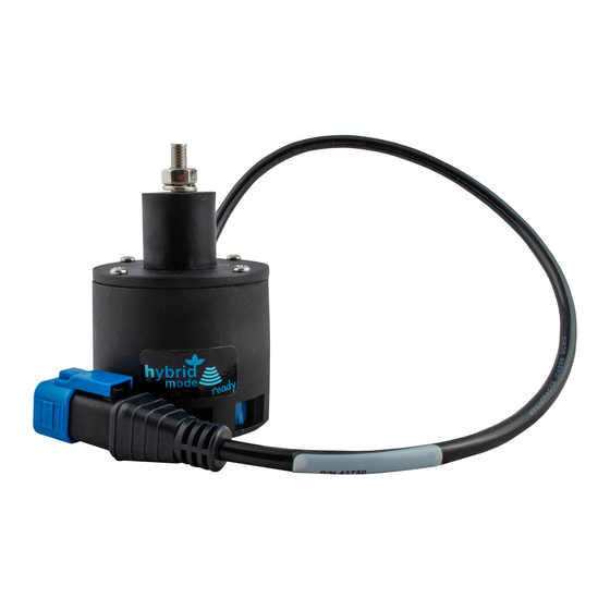
3 Kit Parts Kit Overview Figure 2: CS02 System Parts... - Page 7 Hydraulic Plumbing Figure 3: CS02 Hydraulic Plumbing...
- Page 8 HOSE ASSEMBLY 122R2-04 36 IN L 4FJX 4FJX 44865-05 HYDRAULICS FITTING KIT - CS2 UC5-BC-MANUAL MANUAL OPERATORS UC5 UC5-BC-CS02-INST MANUAL INSTALLATION UC5 CASE IH (3150, 3185, 3200) 106034 UC5 NETWORK 2 PIN PLUG 106035 UC5 NETWORK 12 PIN PLUG (A-KEY)
- Page 9 Hydraulic Fitting Kit Details (P/N: 44865-05) Item Part Number Name Quantity Picture 103345 ELBOW ADAPTER - 6MJ 6FJX90 104614 FEMALE TO MALE ADAPTER - 6FJ 4MJ 104704 CAP - 4FJCN 103312 MALE ADAPTER - 6MB 6MJ 103839 TEE ADAPTER - 6FJXR 6MJT 104369 PLUG - 6MBP 44928...
-
Page 10: Pre-Install Checklist
4 Pre-Install Checklist The pre-install checklist is necessary to check the existing sprayer functionality before the installation. 1. Unfold the sprayer over a flat, unobstructed area (i.e. no power lines…etc.). 2. Ensure all boom-fold operations are functional (place a check mark in boxes below). 3. -
Page 11: Ultrasonic Sensor Installation
5 Ultrasonic Sensor Installation Bracket Assembly Assemble the breakaway sensor bracket as illustrated in Figure 5, following the instructions below. Figure 5: Breakaway Bracket Assembly 1. Compress the spring and insert it together with the collar into the base. 2. Slide the tube through the assembled part. 3. - Page 12 Ultrasonic Sensor Serial Number Arrangement When installing the UC5 sensors, start with the smallest serial number on the left-hand side, and proceed to the largest serial number on the right hand side. Each UC5 sensor has a serial number stamped on the sensor housing. Figure 6: Sensor Serial Number Arrangement...
- Page 13 Ultrasonic Sensor Mounting Guidelines The following guidelines will ensure optimal sensor performance and prevent sensor measurement error. These rules should be followed for both the wing sensors and the main lift (middle) sensor. 1. In its lowest position, the sensor must be 9 inches (23 cm) or more from the ground (A). 2.
- Page 14 If the sensor is mounted to this portion of the boom, the system will force the boom downwards towards the ground as the boom folds backwards. 4. Mount the NORAC UC5 ultrasonic sensor into the sensor bracket and run the sensor cable through the sensor tube.
- Page 15 Main Lift Sensor Installation Figure 9: Main Lift Bracket Assembly 1. There are a variety of ways to mount the main lift bracket on most sprayers. The bracket should position the sensor approximately in the center of the sprayer, forward of the boom. An example of this mounting is illustrated in Figure 10.
-
Page 16: Roll Sensor Installation
6 Roll Sensor Installation Bracket Assembly 1. Securely mount the roll sensors to the included roll sensor brackets using the #6 machine screw and nylon lock-nuts. 2. The orientation of the mounted roll sensor to the roll sensor bracket will depend on the bracket mounting. - Page 17 Roll Sensor Mounting Guidelines: Trapeze-Suspended Booms 1. When mounting the roll sensors, mount one to the trapeze link (boom frame) and one to the trapeze support (chassis). For optimal performance, minimize the distance from the boom frame roll sensor to the pivot point (A) and minimize the vertical distance between the chassis roll sensor and the pivot point (B).
- Page 18 Roll Sensor Mounting on a Case Sprayer Figure 14: Roll Sensor Mounting (Viewed from the rear of sprayer)
-
Page 19: Module Installation
7 Module Installation Control Module 1. Refer to Figure 1 and Figure 15. 2. Securely mount the control module (E01) inside the sprayer cab, using screws or cable ties. 3. Connect the display terminal to the control module using the existing display cable. This cable must be connected to the end of the control module with only one Deutsch connector. - Page 20 Valve Module 1. Install the valve module (E02) to the top of the NORAC valve block. Orient the 6-pin Deutsch (CAN-bus) connectors towards the P and T ports. Output Number Normal Function Left Up Left Down Right Up Right Down...
- Page 21 Input Module 1. Install the input module (E03) on the boom near the sprayer valve block. Secure it to the boom with cable ties. 2. Connect the free end of the CAN-bus cable (C02) from the valve module to the input module.
- Page 22 6. Connect the 12 pin connector on the main lift interface cable (C21) to the black connector on the side of the input module. 7. Insert the other connectors on C21 into the main lift connectors on the sprayer valve block. 8.
-
Page 23: Connecting The Sensors To The Can-Bus
8 Connecting the Sensors to the CAN-Bus 1. Route cable C03 from the input module to the 6-way coupler (E11). 2. Connect both roll sensors to the 6-way coupler. Fasten the 6-way coupler to the boom with cable ties. 3. Connect the main lift sensor to the 6-way coupler using cable C04 and a 2-way coupler (E12). -
Page 24: Hydraulic Installation
Component failure due to oil contamination is not covered under the NORAC UC5 system warranty. It is recommended that a qualified technician perform the hydraulic installation. - Page 25 Valve Block Mounting 1. A suitable mounting location for the valve block is illustrated in Figure 21. 2. Insert the threaded rod into the block and use a hex nut to hold the rod. The block holes are 3/8” NC-1” deep. If bolts are used instead of the threaded rod, ensure the bolts thread in at least 3/8”.
- Page 26 6. Remove the plugs on the sprayer valve block for the pressure and tank ports. Install the 6MB-6MJ (F05) and 6MJ-6FJX90 (F02) fittings into the ports. Connect two hoses (H01) to the 90 degree fittings (F02). 7. Connect the other end of the hoses (H01) to the pressure and tank ports on the NORAC valve block.
-
Page 27: Software Setup
10 Software Setup 1. Start up your sprayer and test the sprayer’s functionality. The display terminal does not need to be powered on for the original boom function switches to operate. Unfold the booms and raise/lower each boom and the main section. Confirm that the cabling and hoses are agreeable to the entire range of motion. -
Page 28: Cable Drawings
11 Cable Drawings 11.1 ITEM C01: 43220-10a - CABLE UC5 NETWORK 14 AWG - 10M 11.2 ITEM C02: 43220-01a - CABLE UC5 NETWORK 14 AWG - 1M... - Page 29 11.3 ITEM C03: 43210-03a - CABLE UC5 NETWORK 18 AWG - 3M 11.4 ITEM C04: 43210-01a - CABLE UC5 NETWORK 18 AWG - 1M...
- Page 30 11.5 ITEM C05: 43210-20a - CABLE UC5 NETWORK 18 AWG - 20M 11.6 ITEM C10: 43230-04a – CABLE UC5 VALVE DT TO DT...
-
Page 31: Cable Uc5 Interface Tilt Gp (Weatherpack)
11.7 ITEM C20: 43240-13b – CABLE UC5 INTERFACE TILT GP (WEATHERPACK) -
Page 32: Cable Uc5 Interface Main Gp (240")
11.8 ITEM C21: 43240-10b – CABLE UC5 INTERFACE MAIN GP (240”) -
Page 33: Cable Uc5 Battery Amp
11.9 ITEM C30: 43250-04a – CABLE UC5 BATTERY AMP... - Page 34 Canada NORAC Systems International Inc. Phone: (+1) 306 664 6711 Toll Free: 1 800 667 3921 Shipping Address: 3702 Kinnear Place Saskatoon, SK S7P 0A6 United States NORAC, Inc. Phone: (+1) 763 786 3080 Toll Free: 1 866 306 6722...
Need help?
Do you have a question about the CS02 and is the answer not in the manual?
Questions and answers