Table of Contents
Advertisement
Quick Links
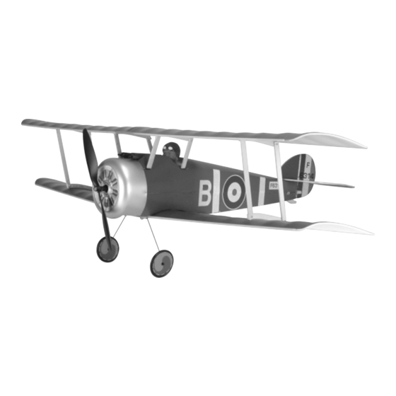
An Electric-Powered, Stand-Off Scale Slow-Flyer from:
INSTRUCTIONS FOR FINAL ASSEMBLY
The Wattage Sopwith Camel EP is distributed
exclusively by Global Hobby Distributors
18480 Bandilier Circle, Fountain Valley, CA 92708
All contents copyright © 2003, Global Hobby
Distributors Version V1.0 January 2003
Kit Product Number 128437
Need help or have any questions? Call us at 1-714-963-0329 or send us an Email at service@globalhobby.net
Specifications:
Wing Span: 38 Inches (Top & Bottom)
Wing Area: 475 Square Inches
Length: 25 Inches
Weight RTF: 13 - 15 Ounces
Wing Loading: 4 - 4.5 Ounces Per Square Foot
Functions: Rudder, Elevator & Throttle
Power: 370 Motor w/4.78:1 Gear Box & Propeller
Radio Required: 3Ch or More Micro w/2 Micro Servos
ESC Required: 5 Amp Micro
Battery Required: 6C 800Mah 5/4AAA NiMH
1
Advertisement
Table of Contents

Subscribe to Our Youtube Channel
Related Manuals for WattAge Sopwith Camel EP


Summary of Contents for WattAge Sopwith Camel EP
- Page 1 An Electric-Powered, Stand-Off Scale Slow-Flyer from: INSTRUCTIONS FOR FINAL ASSEMBLY Specifications: The Wattage Sopwith Camel EP is distributed exclusively by Global Hobby Distributors Wing Span: 38 Inches (Top & Bottom) 18480 Bandilier Circle, Fountain Valley, CA 92708 Wing Area: 475 Square Inches...
-
Page 2: Table Of Contents
In no case shall Wattage's liability exceed the original cost of the purchased kit. In that Wattage has no control over the final assembly or material used for final assembly, no liability shall be assumed for any damage resulting from the use by the user of the final user-assembled product. -
Page 3: Introduction
INTRODUCTION Thank you for purchasing the new Wattage Sopwith Camel EP. Before completing the final assembly of your new airplane, please carefully read through this instruction manual in its entirety. Doing so will ensure your success the first time around! Wattage Sopwith Camel EP Special Features: Foam Wings, Fuselage &... -
Page 4: Section 1: Our Recommendations
The ESC you choose should be capable of handling no less than 5 amps continuous current. Again, lighter is better. Your ESC should weigh no more than .85 ounces including the wiring and switch. We suggest using the Wattage IC-5A Micro electronic speed control. -
Page 5: Section 2: Tools And Supplies Required
Hitec crystal. SECTION 2: TOOLS AND SUPPLIES REQUIRED The tools and supplies listed below will be necessary to finish the assembly of your Sopwith Camel EP. We suggest having these items on hand before beginning assembly. Kwik Bond 5 Minute Epoxy # 887560... -
Page 6: Section 3: Kit Contents
WARNING The Sopwith Camel EP is constructed of foam. It is very important that you use no solvents, Cyanoacrylate (C/A) glue, or paint that can damage foam. If any of these chemicals comes in contact with the foam parts, the parts will be destroyed and will not be covered under warranty. -
Page 7: Section 4: Fuselage Assembly
SECTION 4: FUSELAGE ASSEMBLY YOU'LL NEED THE FOLLOWING PARTS FROM THE KIT: (1) Plywood Die-Cut Sheet (1) Fuselage Halves (Top & Bottom) YOU'LL NEED THE FOLLOWING TOOLS AND SUPPLIES: Kwik Bond 5 Minute Epoxy Paper Towels Excel Modeling Knife Rubbing Alcohol Ruler NHP Epoxy Mixing Sticks Pencil... - Page 8 Step 2: Joining the Fuselage Halves Using a ruler and pencil, carefully measure and draw three marks on each side of the top fuselage half. The first mark should be located 1-1/2" in front of the back of the fuselage, the second mark should be 2-1/8"...
-
Page 9: Section 5: Gear Box & Cowling Installation
Fit the fuselage halves back together and realign them. Remove any excess epoxy using a paper towel and rubbing alcohol, and hold the fuselage halves together until the epoxy sets up. Important Tip: We don't suggest using pieces of masking tape to hold the fuselage halves together, because the paint will be damaged when you remove the tape. - Page 10 Test-fit the motor plate onto the front of the fuselage. To align it properly, the two notches in the motor plate should be even with the seam between the two fuselage halves and the motor plate should be centered over the vertical centerline you drew previously.
- Page 11 ® Using a pair of scissors, cut a 2" long piece of Velcro ® from the strip of Velcro provided. ® Remove the protective backing from the piece of Velcro and adhere it to the front of the fuselage, as shown. ®...
-
Page 12: Section 6: Landing Gear Installation
Using a pair of scissors, carefully cut out the flight battery access hole in the bottom of the cowling. Using 220 grit sandpaper, lightly sand the edges of the access hole smooth and straight. IMPORTANT Before installing the cowling in the next procedure, apply the engine decal to the front of the cowling. - Page 13 Position the plywood landing gear mounting plate onto the bottom of the fuselage. The front edge of the plate should be 7/8" behind the front of the fuselage and the ends of the plate should be equal distance from the sides of the fuselage. When satisfied with the fit, glue the mounting plate into place using a generous amount of 5 minute epoxy.
-
Page 14: Section 7: Stabilizer Installation
Using a modeling knife, carefully cut a 1/8" deep slot in the bottom, back of the fuselage, the same dimension as the base of the plywood tail skid. Locate the back edge of the notch 1/4" in front of the back of the fuselage and make sure that the notch is centered between the fuselage sides. - Page 15 Using 220 grit sandpaper with a sanding block, carefully sand a shallow 45º bevel in the bottom of the leading edge of the elevator. Place the prebent elevator joiner wire onto the bottom of the elevator. Center the wire over the middle of the elevator, making sure that the front of the wire is even with the bevel in the leading edge.
- Page 16 Step 2: Hinging the Elevator Turn the elevator right side up and push the leading edge up against the trailing edge of the stabilizer. With the ends of the elevator even with the ends of the stabilizer and with no gaps in the hinge line, hinge the elevator to the stabilizer using a strip of clear plastic tape.
- Page 17 Using the tip of your modeling knife, punch out the small die-cut square in the leading edge of the rudder. Using a pair of scissors, cut out the right- and left-side rudder decals from the decal sheet. Carefully apply one decal to each side of the rudder, making sure to line up the front edge of each decal with the leading edge of the rudder.
-
Page 18: Section 8: Control Systems Installation
SECTION 8: CONTROL SYSTEMS INSTALLATION YOU'LL NEED THE FOLLOWING PARTS FROM THE KIT: (2) Nylon Clevises (2) 15-3/4" Threaded Wires (2) Nylon Control Horns (1) Double-Sided Foam Tape (2) Nylon Control Horn Backplates YOU'LL NEED THE FOLLOWING TOOLS AND SUPPLIES: # 0 Phillips Head Screwdriver Scissors Magnum Z-Bend Pliers... - Page 19 Using the tip of your modeling knife, carefully remove the die-cut square from the leading edge of the elevator. Push one control horn through the die-cut hole in the elevator, making sure that the tip of the control horn is toward the bottom of the elevator.
- Page 20 Remove the servo horn. Using a 1/16" drill bit, enlarge the hole in the servo arm that is 1/4" out from the center of the servo horn. Attach the servo horn to the Z-Bend, then attach the servo horn to the servo, making sure it's centered. Carefully install and tighten the servo horn retaining screw, provided with your servo, to secure the servo horn into place.
- Page 21 Place a single arm servo horn onto the servo. Mark where the pushrod wire crosses the hole that is 1/4" out from the center of the servo horn, then make a Z-Bend in the pushrod wire. Cut off the excess wire and attach the pushrod wire to the servo arm.
-
Page 22: Section 9: Pilot & Machine Gun Installation
SECTION 9: PILOT & MACHINE GUN INSTALLATION YOU'LL NEED THE FOLLOWING PARTS FROM THE KIT: (1) Molded Pilot Bust (2) Molded Machine Guns YOU'LL NEED THE FOLLOWING TOOLS AND SUPPLIES: Kwik Bond 5 Minute Epoxy Small & Medium Paint Brushes - Optional Modeling Knife - Optional Acrylic Paint (Assorted Colors) - Optional Pencil - Optional... -
Page 23: Section 10: Top & Bottom Wing Assembly
SECTION 10: TOP & BOTTOM WING ASSEMBLY YOU'LL NEED THE FOLLOWING PARTS FROM THE KIT: (4) Fiberglass Dowels (1) Right & Left Wing Panels (Top & Bottom) (1) Plywood Die-Cut Sheet (2) Aluminum Tubes (1 Straight, 1 Bent) YOU'LL NEED THE FOLLOWING TOOLS AND SUPPLIES: Kwik Bond 5 Minute Epoxy Rubbing Alcohol 220 Grit Sandpaper w/Sanding Block... - Page 24 Important Tip: Two fiberglass dowels and an aluminum tube are provided to strengthen the wing. For the strongest joint possible, it's important that these parts be installed correctly. The aluminum tube is prebent to the correct dihedral angle (in this case straight) and the two dowels are designed to be glued to the entire length of the leading edge of the wing.
- Page 25 Important Tip: In the next procedure make sure that the aluminum tube is angled straight up and not toward the front or back of the wing panel. This tube sets the dihedral angle of the bottom wing panels, so its alignment is important. Line up the crease in the middle of the aluminum tube with the root end of one wing panel and carefully glue the fiberglass dowel to the leading edge of the wing.
-
Page 26: Section 11: Top & Bottom Wing Installation
SECTION 11: TOP & BOTTOM WING INSTALLATION YOU'LL NEED THE FOLLOWING PARTS FROM THE KIT: (12) M2 x 8 Wood Screws (2) Plywood Die-Cut Sheets (4) Prebent Cabane Strut Wires (1) M3 x 25 Wood Screw (4) Nylon Cabane Strut Mounts YOU'LL NEED THE FOLLOWING TOOLS AND SUPPLIES: Kwik Bond 5 Minute Epoxy Ruler... - Page 27 Using 220 grit sandpaper, lightly sand the four prebent cabane strut wires to roughen the metal. IMPORTANT Roughening the metal will allow the glue to stick better to it, making the overall joint stronger. Using a generous amount of thick C/A, carefully glue one prebent cabane strut wire to the edge of one of the plywood cabane struts, making sure that the wire is centered on the edge of the strut and that there is a 1/16"...
- Page 28 Step 2: Assembling the Outer Wing Struts Carefully drill a 1/16" diameter hole through both ends of each of the four outer wing struts, as shown. Each hole should be located 3/16" from the end of the strut and centered between the sides of the strut.
- Page 29 Test-fit the right-side curved wing strut mount to the bottom of the wing, aligning it over the vertical line you drew. To position the mount properly, the back edge of the mount should be 1-5/8" in front of the trailing edge and the mount should be at a 90º...
- Page 30 Using a modeling knife, cut out two lengths of scrap plywood from the two leftover die-cut sheets. Using a 1/16" diameter drill bit, drill two holes through each piece of plywood exactly 3-5/16" apart. Using a ruler and a pencil, draw a vertical centerline between the two holes.
- Page 31 While holding the wing in position, turn the fuselage right-side up and look at the wing saddle. There should be few or no gaps between the top of the wing and the wing saddle. If there is a gap at the leading edge of the wing, please follow the next procedure below to eliminate it.
-
Page 32: Section 12: Final Assembly
Mix a small quantity of 5 minute epoxy and glue each of the four nylon cabane strut mounts into the slots you cut. Remove any excess epoxy using a paper towel and rubbing alcohol, and allow the epoxy to completely cure before proceeding. - Page 33 IMPORTANT The Wattage IC-5A Micro ESC does not feature an on/off switch. Please be aware that when you plug your flight battery into this ESC, the airborne system and motor will be powered up.
-
Page 34: Section 13: Balancing The Sopwith Camel Ep
SECTION 14: CONTROL THROWS We recommend setting up the Sopwith Camel EP using the control throws listed below. These control throws are suggested for initial test-flying because they will allow the airplane to fly smoother and make it easier to control. -
Page 35: Section 15: Preflight Check & Safety
Once you're familiar with the flight characteristics of the airplane, you might want to increase the control throws to the sport-flying settings listed below. These control throws will make the airplane more responsive and allow you to do basic aerobatics with ease. SPORT-FLYING Rudder: 3/4"... -
Page 36: Section 16: Flying The Sopwith Camel Ep
The airplane tracks well and will handle very light winds quite easily. It is a slow-flyer though, so we don't recommend flying the Sopwith Camel EP in winds greater than 5 - 10 MPH. With full power and the control throws set to the Sport-Flying settings, basic aerobatics are completed with ease. -
Page 37: Section 17: Replacement Parts
We suggest ordering directly from your local dealer. If your dealer does not stock Wattage products, you can order directly from us at the address shown below:... -
Page 38: Full-Size Cabane Strut & Wing Strut Drawings
Visit our website at http://watt-age.globalhobby.com or for Customer Service at http://globalservices.globalhobby.com... -
Page 39: Product Evaluation Sheet
Global Hobby Distributors will not disclose the information it collects to outside parties. Global Hobby Distributors does not sell, trade, or rent your personal information to others. Your privacy is important to us. Kit: Wattage Sopwith Camel EP # 128437 Was any of the assembly difficult for you? If yes, please explain. - Page 40 _____________________________ _____________________________ Post Office will not deliver _____________________________ without proper postage (Return Address Here) Global Hobby Distributors Attn: Global Services 18480 Bandilier Circle Fountain Valley CA 92728-8610 Fold along dotted line Visit our website at http://watt-age.globalhobby.com or for Customer Service at http://globalservices.globalhobby.com...
Need help?
Do you have a question about the Sopwith Camel EP and is the answer not in the manual?
Questions and answers