Table of Contents
Advertisement
HUSSONG MANUFACTURING CO., INC.
SP-34 LOG
SP-34 MILLIVOLT
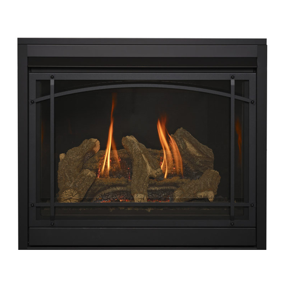
Models #SP-34-LE and #SP-34-MV
Direct Vent Gas Fireplaces
WARNING:
FIRE OR EXPLOSION HAZARD
Failure to follow safety warnings exactly
could result in serious injury, death, or
property damage.
ͷ Do not store or use gasoline or other
flammable vapors and liquids in the
vicinity of this or any other appliance.
ͷ WHAT TO DO IF YOU SMELL GAS
• Do not try to light any appliance.
• Do not touch any electrical switch; do
not use any phone in your building.
• Leave the building immediately.
• Immediately call your gas supplier from
a neighbor's phone. Follow the gas
supplier's instructions.
• If you cannot reach your gas supplier,
call the fire department.
ͷ Installation and service must be performed
by a qualified installer, service agency or
the gas supplier.
This
appliance
an
aftermarket,
manufactured home (USA only) or mobile
home, where not prohibited by local codes.
This appliance is only for use with the type
of gas indicated on the rating plate. This
appliance is not convertible for use with
other gases, unless a certified kit is used.
Hussong Mfg. Co., Inc. • SP-34-LE & SP-34-MV
may
be
installed
permanently
located,
INSTALLER: Leave this manual with the appliance.
CONSUMER: Retain this manual for future reference.
Tested &
Listed By
C
OMNI-Test Laboratories, Inc.
in
English
and
available through your local dealer. Visit our website
www.kozyheat.com or scan the QR code for our mobile app.
Les manuels d'installation en français et en anglais sont
disponibles chez votre détaillant local. Visitez www.kozyheat.
com ou scannez ce code QR pour notre application mobile.
Report No: 0216GF052S • Rev. 01, May 2016
Installation and
Operation Manual
Portland
Oregon USA
US
French
installation
manuals
are
Advertisement
Table of Contents

Subscribe to Our Youtube Channel
Related Manuals for kozy heat SP-34-LE


Summary of Contents for kozy heat SP-34-LE
- Page 1 INSTALLER: Leave this manual with the appliance. CONSUMER: Retain this manual for future reference. Hussong Mfg. Co., Inc. • SP-34-LE & SP-34-MV Report No: 0216GF052S • Rev. 01, May 2016...
- Page 3 CONGRATULATIONS! We welcome you as a new owner of a Kozy Heat gas fireplace. Kozy Heat products are designed with superior components and materials, and assembled by trained craftsmen who take pride in their work. To ensure you receive a quality product, the burner and valve assembly are 100 percent test-fired, and the complete fireplace is thoroughly inspected before packaging.
-
Page 5: Table Of Contents
9.3 #SP34-028 Optional Fan Kit ............33 3.4 Fireplace Wall Enclosure ............14 10.0 OPERATING INSTRUCTIONS ..........34 3.5 Floor Support and Protection ............15 10.1 Lighting Instructions (#SP-34-LE) ..........34 3.6 Recess Construction ..............15 10.2 Lighting Instructions (#SP-34-MV) .........36 3.7 Vent Termination Framing .............16 11.0 ADJUSTMENT ................ -
Page 7: Introduction
1.0 INTRODUCTION 1.1 Appliance Certification 1.2.3 Signage A metal or plastic identification plate shall be permanently Laboratory: OMNI-Test Laboratories in Portland, Oregon mounted to the exterior of the building at a minimum of eight (8) Standards: feet above grade directly in line with the exhaust vent terminal ANSI Z21.88-2014/CSA 2.33-2014, Vented Gas Fireplace Heaters for the horizontally vented gas fueled heating appliance or equipment. -
Page 8: Specifications
4 in (102 mm) Restrictor Plate SP34-HHS Vent Heat Shield Assembly 2.1.1 Additional Components Required Refer to Section 7.0 Venting on page 22 for approved vent systems. 2.2 Heating Specifications Models SP-34-LE and SP-34-MV Natural Gas LP Gas Maximum 20,500 Btu/h 20,500 Btu/h Input Rating (6.0 kW) -
Page 9: Appliance Dimensions
2.3 Appliance Dimensions TOP VIEW ⁄ ” (131mm) 14” (356mm) LEFT SIDE FRONT VIEW RIGHT SIDE ⁄ ” ⁄ ½ ” ” (848mm) (519mm) (786mm) ½ ” 28” ¾ ” (342mm) (711mm) (198mm) 34” (864mm) Figure 2.1, Appliance Dimensions SPECIFICATIONS 9... -
Page 10: Safety Barrier Dimensions
2.4 Safety Barrier Dimensions WARNING: A barrier designed to reduce the risk of burns from the hot viewing glass is provided with this appliance and shall be installed for the protection of children and other at-risk individuals. If the barrier becomes damaged, the barrier shall be replaced with Hussong Mfg.’s barriers for this appliance. -
Page 11: Framing
3.0 FRAMING 3.1 Appliance Placement Considerations WARNING: Due to high temperatures, the appliance should be located out of traffic and away from furniture and draperies. • This appliance must be installed on a level surface capable of supporting the fireplace and venting. If possible, place the STAND-OFF BRACKETS, AS SHIPPED fireplace in a position where the vent terminates between two studs, eliminating the need for any additional framing. -
Page 12: Clearances To Combustibles
3.3 Clearances to Combustibles Table 3.1, Minimum Appliance Clearances to Combustible Material From appliance top stand-off brackets 0 in 0 mm From facing material 1” (25 mm) stand-off flange 0 in 0 mm From appliance back stand-offs 0 in 0 mm From appliance corners 1/4 in 6 mm... -
Page 13: Typical Installation Options
3.3.1 Typical Installation Options TYPICAL VERTICAL INSTALLATION TYPICAL HORIZONTAL INSTALLATION ½ ½ ” ” (13mm) (13mm) 14” 14” (356mm) (356mm) ½ ½ ” ” (876mm) (876mm) TYPICAL CORNER INSTALLATION ⁄ ” (334mm) ½ ” (978mm) ¼ ” (6mm) ¼ ” ½... -
Page 14: Fireplace Wall Enclosure
3.4 Fireplace Wall Enclosure • Framing dimensions should allow for wall covering thickness and fireplace facing materials. Adjust rough opening size as WARNING: Provide adequate clearances around air openings necessary to maintain minimum clearance requirements. into the combustion chamber. Provide adequate clearance in •... -
Page 15: Floor Support And Protection
3.5 Floor Support and Protection • Floor protection in front of the fireplace is not required. 12” Combustible material may be used if installing a hearth (305mm) extension. Consider the thickness of the hearth extension 14” finishing material if building a fireplace platform. The bottom (356mm) of the fireplace must be level with finished hearth extension for proper fit of the safety barrier. -
Page 16: Vent Termination Framing
3.7 Vent Termination Framing IMPORTANT: Vent cap location must be in compliance with NATURAL AND LP GAS RIGID PIPE MINIMUM HORIZONTAL TERMINATION FRAMING Section 6.2 Minimum Termination Clearances on page 21. WARNING: DO NOT RECESS THE VENT CAP INTO WALL OR SIDING. -
Page 17: Facing And Finishing
4.0 FACING AND FINISHING 4.1 Secure the Appliance NOTE: The nailing tabs on both sides of the appliance allow installations for a flush mount, 1/2 in (13 mm) facing material, or 5/8 in (16 mm) facing material. CAUTION: The fireplace must be secured to framing regardless of finishing material used. -
Page 18: Mantel Requirements
4.2 Mantel Requirements 12” (305mm) 1” (25mm) 6” (152mm) 42” 3/4” (1067mm) (19mm) TRIM ½ 37” ” (940mm) (851mm) COMBUSTIBLE FLOORING 18 FACING AND FINISHING... -
Page 19: Gas Line Connection
• For pressure testing instructions, refer to Section 11.1 Gas Pressure Testing on page 37. Table 5.1, Inlet Pressure Requirements - SP-34-LE (Electronic) Gas Pressure Natural Gas LP Gas Minimum Inlet 5”... -
Page 20: Termination Locations
6.0 TERMINATION LOCATIONS 6.1 Vertical Vent Cap Termination WARNING: This appliance must not share or be connected to a chimney flue serving a separate solid-fuel burning appliance. LOWEST DISCHARGE OPENING APPROVED CAP MINIMUM *12” (.30m) APPROVED VENT PIPE ROOF PITCH = x/12 H - MINIMUM HEIGHT FROM ROOF TO LOWEST DISCHARGE OPENING *If vent is closer than 12 in (.30 m), it must terminate at least 2... -
Page 21: Minimum Termination Clearances
6.2 Minimum Termination Clearances AREA WHERE TERMINAL IS NOT PERMITTED Figure 6.2, Vent Cap Locations Canadian installations US installations Clearance above grade, veranda, porch, deck, or balcony 12 in (30 cm) 12 in (30 cm) Clearance to window or door that may be opened 12 in (30 cm) 9 in (23 cm) Clearance to permanently closed window (recommended to prevent condensation... -
Page 22: Venting
For vent EXCELDirect Horizontal & Vertical restriction plate recommendations after vent installation, see Section 11.2.2 Vent Restriction on page 40. Kozy Heat 700 Series Flexible Vent Horizontal Only System Metal Fab Direct Vent Chimney Horizontal &... -
Page 23: Vertical Terminations
7.5 Vertical Terminations NATURAL GAS AND LP GAS VERTICAL VENT DIAGRAM (A) Stand-off Heat Shields (D) Horizontal Vent Heat Shield IMPORTANT: The vertical vent heat shield must be installed for (not applicable) (B) 90° Elbow (not applicable) all venting applications. Refer to Section 7.8 on page 26. (E) Termination Cap (C) Vertical Vent Heat Shield NOTE: Attic insulation shields may be insulated using unfaced... -
Page 24: Combination Venting
7.6 Combination Venting NATURAL GAS AND LP GAS HORIZONTAL VENTING DIAGRAM (A) Stand-off Heat Shields (D) Horizontal Vent Heat Shield IMPORTANT: The horizontal vent heat shield must be installed (B) 90° Elbow (E) Termination Cap when using a 90° elbow off the top of the appliance.. Refer to (C) Vertical Vent Heat Shield Section 7.8 on page 26. -
Page 25: 700-2 Series Direct Vent Termination Kit(S)
7.7 #700-2 Series Direct Vent wall, and seal. (OPTIONAL) insulate the wall thimble with any unfaced Termination Kit(s) insulation products listed as non-combustible per ASTM E 136. IMPORTANT: The vertical vent heat shield included with this fireplace must be installed for every type of venting application. Apply a liberal bead of exterior sealant around outer edge of termination box (A), placing assembly through the wall-pass IMPORTANT: The flex pipe is permanently attached to the... -
Page 26: Vent Heat Shield Assembly Installation
7.8 Vent Heat Shield Assembly Installation IMPORTANT: The vertical vent heat shield MUST be installed for every type of venting application. The horizontal vent heat VENT STAND-OFF TAB shield must be installed when using a 90° elbow off the top of the appliance. -
Page 27: Fireplace Setup
8.0 FIREPLACE SETUP 8.1 Safety Barrier Installation 8.2 Glass Frame Assembly WARNING: Do not operate this fireplace with the glass removed, 8.1.1 Safety Barrier Screen (#SP34-SCR) cracked, or broken. Replacement of the glass assembly should Locate the (4) slots located on each side of the fireplace be done by a licensed or qualified service person. -
Page 28: Sp34-500 Log Set Installation
8.3 #SP34-500 Log Set Installation Align the holes in the bottom of log SP34-1 with the mounting pins on the log plates at the back of the firebox. Push log CAUTION: Do not place logs or lava rock directly over down to seat. -
Page 29: Control Board Removal And Installation
8.4 Control Board Removal and Installation WARNING: Avoid burns or personal property damage by using appropriate protection to remove any components if the burner and/or pilot have been burning. WARNING: DO NOT operate this appliance without the sealing gasket (located under the control board) in place. If the sealing gasket is damaged, it must be replaced. -
Page 30: Electrical Information
9.0 ELECTRICAL INFORMATION 9.2.2 Continuous Pilot Ignition WARNING: Do not use this fireplace if any part has been under water. Immediately call a qualified service technician to inspect System (Millivolt) this appliance and to replace any part of the control system and CAUTION: Do connect high voltage (115V) wire to the gas valve. - Page 31 PILOT APPLIANCE GROUND STAR IGNITER MAIN ON/OFF SWITCH BATTERY FLAME MALE END SENSOR PACK IPI/CPI SWITCH 886 PROFLAME PILOT BURNER Figure 9.1, Electronic Gas Valve Wiring Schematic with ON/OFF Rocker Switch PILOT WIRE ASSEMBLY APPLIANCE GROUND STAR IGNITER FLAME MALE END SENSOR BATTERY PACK IPI/CPI...
- Page 32 THERMOPILE THERMOCOUPLE PIEZO PILOT ON/OFF ROCKER SWITCH Figure 9.3, Millivolt Gas Valve Wiring Schematic with ON/OFF Rocker Switch THERMOPILE THERMOCOUPLE PIEZO PILOT WIRE ASSEMBLY Attach gas valve connectors to the wall switch/thermostat wires, connect to top and bottom terminals marked TH and TP-TH on gas valve Figure 9.4, Millivolt Gas Valve Wiring Schematic with Thermostat or Wall Switch Wiring 32 ELECTRICAL INFORMATION...
-
Page 33: Sp34-028 Optional Fan Kit
9.3 #SP34-028 Optional Fan Kit WARNING - Electrical Grounding Instructions: This appliance is equipped with a three-prong (grounding) plug for your protection against shock hazard and should be plugged directly into a properly grounded three-prong receptacle. Do not cut or remove the grounding prong from this plug. -
Page 34: Operating Instructions
10.0 OPERATING INSTRUCTIONS 10.1 Lighting Instructions (#SP-34-LE) is recommended to leave the fan off during this period to help speed the paint curing process. • When this fireplace is initially lit, condensation will appear on • This fireplace may produce noises of varying degree as it the glass. - Page 35 10.1.1 Pilot Ignition Selection (IPI/CPI) 10.1.2 Flame Height and Heat Output Adjustment Model #SP-34-LE (electronic ignition system) has the option of a continuous (standing) pilot. This features allows the system to Model #SP-34-LE (electronic ignition system) is equipped with a...
-
Page 36: Lighting Instructions (#Sp-34-Mv)
10.2 Lighting Instructions (#SP-34-MV) speed the paint curing process. • This fireplace may produce noises of varying degree as it • When this fireplace is initially lit, condensation will appear on heats and cools due to metal expansion and contraction. This the glass. -
Page 37: Adjustment
11.0 ADJUSTMENT 11.1 Gas Pressure Testing Table 11.1, Pressure Requirements - OAK-18-LE (Electronic) NOTE: The appliance and its appliance main gas valve must Gas Pressure Natural Gas LP Gas be disconnected from the gas supply piping system during any Inlet Pressure 5”... - Page 38 11.1.2 Millivolt Gas Pressure Testing Table 11.2, Pressure Requirements - OAK-18-MV (Millivolt) IMPORTANT: Pressure check taps for manifold (outgoing) and Gas Pressure Natural Gas LP Gas inlet (incoming) pressure have been incorporated into the valve. Inlet Pressure 5” - 10.5” WC 11”...
-
Page 39: Burner Flame Adjustments
11.2 Burner Flame Adjustments IMPORTANT: Slight adjustments to the venturi opening will create dramatic results. Adjust at slight increments until WARNING: To avoid property damage or personal injury, allow desired look is achieved. Always burn the fireplace for at least the fireplace ample time to cool before making any adjustments. -
Page 40: Restrictor Plate Installation
11.2.2 Vent Restriction RESTRICTOR PLATE WARNING: To avoid property damage or personal injury, allow REMOVE CIRCLE TO the fireplace ample time to cool before making any adjustments. CREATE LESS RESTRICTION WARNING: Improper vent installation may cause the burner flames to lift or “ghost.” Perform a visual check on flame appearance after restrictor adjustment to ensure proper performance. -
Page 41: Troubleshooting
12.0 TROUBLESHOOTING 12.1 Electronic Ignition System with correct polarity. • Verify all connections between the wire harnesses and the ATTENTION: Troubleshooting must be performed by a qualified system components are proper and positive. technician. • Verify inlet pressure meets the recommended inlet pressure. Before proceeding with the steps in the following troubleshooting If necessary, adjust line pressure regulator. - Page 42 Issue Cause Solution Pilot and burner No LP (propane) gas in tank Check LP (propane) tank. Refill if necessary. extinguish while in Incorrect glass assembly Refer to Section 8.2 Glass Frame Assembly on page 27. operation installation Incorrect vent cap installation Adjust if necessary.
-
Page 43: Continuous Pilot Ignition (Millivolt) System
12.2 Continuous Pilot Ignition (Millivolt) System ATTENTION: Troubleshooting must be performed by a qualified technician. Issue Cause Solution Verify piezo igniter is properly grounded. Tighten mounting fastener, No spark from electrode Piezo igniter wiring if required. to pilot when piezo button disconnection is triggered Check and repair, if necessary, the wire connections between the... - Page 44 Issue Cause Solution Burner will not light Lighting instructions not Turn gas control knob to ON position. followed Turn the ON/OFF rocker switch to ON position. Put wall switch, remote control, or thermostat in heat demand position. Plugged main burner orifice Remove blockage as necessary.
-
Page 45: Maintenance
13.0 MAINTENANCE 13.2 Fan (optional) ATTENTION: Installation and repair should only done by a qualified service person. The appliance should be inspected CAUTION: Label all wires prior to disconnection when servicing before use and at least annually by a professional service controls. -
Page 46: Replacement Parts List
14.0 REPLACEMENT PARTS LIST Replacement parts are available through your local dealer. Contact your local dealer for availability and pricing. SP-34-LE CONTROL BOARD AND PARTS Control Board - NG SP34-140 Pilot Orifice - NG #62 700-166 Control Board - LPG... -
Page 47: Limited Warranty
Hussong Manufacturing Co., Inc. warranties to the original all times, according to the operating instructions furnished. purchaser of this Kozy Heat Fireplace, that it is free of defects in This warranty is limited to defects in material and workmanship. It materials and workmanship at the time of manufacture. -
Page 49: Lifetime Warranty
Kozy Heat Fireplace will not be defective in than those incurred by Hussong Manufacturing Co., Inc. to repair material or workmanship under normal use and service for as long or replace the defective component.
Need help?
Do you have a question about the SP-34-LE and is the answer not in the manual?
Questions and answers