
Related Manuals for 3onedata IES7110 3GS Series


Summary of Contents for 3onedata IES7110 3GS Series
- Page 1 User manual IES7110-3GS series Managed Industrial Ethernet switches user manual Version 1.0.0, Jun. 2014 www.3onedata.com...
- Page 2 User manual IES7110-3GS series user manual Statement Copyright Notice Information in this document is reserved by Shenzhen 3onedata Technology Co.,Ltd. Reproduction and extract without permission is prohibited. Trademarks Notice is registered trademarks of Shenzhen 3onedata Technology Co.,Ltd. All other trademarks or registered marks in this manual belong to their respective manufacturers.
-
Page 3: Table Of Contents
User manual Content CONTENT ....................... 错误!未定义书签。 CHAPTER 1 SUMMARIZE................错误!未定义书签。 1.1 I ..............................5 NTRODUCTION 1.2 F ................................5 EATURES CHAPTER 2 HARDWARE DESCRIPTION................. 5 2.1 P ..............................6 ANEL DESIGN 2.2 P ..............................7 OWER INPUT 2.3 R ............................7 ELAY CONNECTION 2.4 C ..............................7 ONSOLE PORT... - Page 4 User manual CHAPTER 7 FUNCTION SETTING.................... 53 7.1 DIP SWITCH..............................53 7.1.1 Default factory..............................53 CHAPTER 8 REPAIR AND SERVICE............错误!未定义书签。 8.1 I SERVICE......................错误!未定义书签。 NTERNET ............... 错误!未定义书签。 CALL TO TECHNOLOGY SUPPORT DEPARTMENT 8.3 REPAIR OR REPLACE....................错误!未定义书签。 APPENDIX 1 GLOSSARY TABLE..............错误!未定义书签。 APPENDIX 2 PERFORMANCE PARAMETER................
-
Page 5: Chapter 1 Summarize
User manual Chapter 1 Summarize 1.1 Introduction IES7110-3GS series is a industrial grade, managed and redundancy Ethernet switch. IES71 10-3GS series provided some kinds of advanced network managed function, like as: SW-Ring redu ndancy ring network, VLAN, Trunking, Quality of Service, Speed control, port mirroring, fault alar m and firmware upgrade online. -
Page 6: Chapter 2 Hardware Description
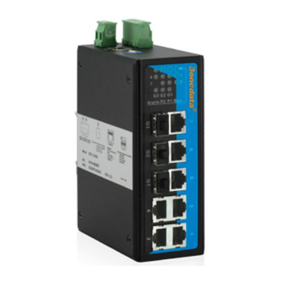
User manual CHAPTER 2 HARDWARE DESCRIPTION 2.1 Panel design IES7110-3GS-P(12/48VDC) 1. Ground screw 2. PWR1/PWR2 power input 3. Relay output terminal block 4. DIP switch 5. CONSOLE port 6. DIN-Rail mount 7. Wall mount screw hole 8. 10Base-T /100Base-TX port 9. -
Page 7: Power Input
User manual Power supply input Front view Top view IES7110-3GS series top panel provided 4 bit power supply input terminal block, support DC input. DC power supply input supported redundancy function, provided PWR1 and PWR2 power input, can use for single, and can connect 2 separately power supply system, use 1 pair terminal block connect the device at the same time. -
Page 8: Communication Port
User manual 2.5 Communication port IES7110-3GS series Industrial Ethernet switch provided 7 port 10Base-T/100BaseTX(RJ45) and 3 port 1000Base-FX (SFP). 10Base-T /100Base-TX Ethernet port 10Base-T/100Base-TX Ethernet port is located on front panel and the type is RJ45. The pinout of RJ45 port connects to UTP or STP. -
Page 9: Led Indicator
User manual Suppose: If you make your own cable, we advise to label the two sides of the cable with the same letter (A-to-A and B-to-B, shown as below, or A1-to-A2 and B1-to-B2). 1000SFP fiber port(mini-GBIC) 1000BaseSFP fiber port adopts gigabit mini-GBIC transmission, can choice different SFP module according to different transfer distance. - Page 10 User manual Before installation, confirm that the work environment meet the installation require, including the power needs and abundant space. Whether it is close to the connection equipment and other equipments are prepared or not. 1. Avoid in the sunshine, keep away from the heat fountainhead or the area where in intense EMI. 2.
- Page 11 User manual Wiring Requirements Cable laying need to meet the following requirements, 1. It is needed to check whether the type, quantity and specification of cable match the requirement before cable laying; 2. It is needed to check the cable is damaged or not, factory records and quality assurance booklet before cable laying;...
-
Page 12: Chapter 3 Appearance And Dimension
User manual Chapter 3 Appearance and Dimension 3.1 Appearance IES7110-3GS(12/48VDC) 3.2Dimension... - Page 13 Please check the packaging and accessories by your first using. Please inform us or our distributor if your equipments have been damaged or lost any accessories, we will try our best to satisfy you. Description Quantity 3onedata Industrial Ethernet switch User manual Warranty card...
-
Page 14: Chapter 5 Network Configuration
User manual CHAPTER 5 NETWORK CONFIGURATION IES7110-3GS series can access, configuration and management through WEB, the user manual will introduce the operations step by step. 5.1 Configure PC’s IP Address IES7110-3GS series default address is: 192.168.1.254, subnet mask is: 255.255.255.0. When entering into IES7110-3GS series Web interface through internet explorer, the IP address of IES7110-3GS series and PC must be in the same Local Area Network. -
Page 15: Chapter 6 Web Management
User manual CHAPTER 6 WEB MANAGEMENT IES7110-3GS series have WEB server inside, can manage and maintenance the device very intuitive through WEB interface 6.1 Configurate preparing 1. The lowest requirement for user's computer is as below: Install operating system (Windows XP/2000,etc) ... -
Page 16: System Status
User manual Main Menu Function System Display device information and port information such as software System Status information version, IP address, etc. Display and configure information of each port: such as connection Port settings status, configuration modes, flow status etc. Port Configuration Bandwidth... - Page 17 User manual Figure 6.2.1 Configuration Items Description Name Network mark of the device. It is convenient for management tools to judge. Serial No. Serial number of the device. It is convenient for device management. Description Description of the product features. Contact Information Contact information of the operator for device maintenance.
-
Page 18: Port Configuration
User manual (Figure 6.2.3) Port 3,7...G1,if the port is connected properly the status should be LINK, no connection status will be LOS. 6.3 Port Configuration 6.3.1 Port Settings The port configuration interface mainly include port type(Electric port or optical port), setup speed mode and duplex mode,flow control. - Page 19 User manual (Figure 6.3.1 ) Configuration Items Description Port Port name, corresponding to mark in panel. Type Display port type (TX or FX). Speed Display configurable speed of port or auto-negotiation mode. Auto-negotiation(AUTO),full duplex(FULL), half duplex(HALF) Duplex optional, default mode is auto-negotiation mode. Configurable port enable or disable.
-
Page 20: Bandwidth Management
User manual Port Enable This item provides a device to enable/disable the port. When choosing disable, the device would cut off power supply of this port. Even if other device is connected to this port, all status indicators of this port are OFF. Only enable this port, all settings about this port will be valid. - Page 21 User manual (Figure 6.3.2) Ingress Bandwidth Configuration: Ingress bandwidth limit includes 4 kinds: 1 All frames; 2 Broadcast&Multicast &unicast frames; 3 Broadcast&Multicast only; 4 Broadcast only “No limit” stands for no limitation, the rate of low priority queues (L)can be setted:128k, 256k, 512k, 1M, 2M, 4M, 8M.The rate of normal priority queues(N)...
-
Page 22: Vlan
User manual Broadcast only The ingress rate is related to CoS priority. Priority Queue is based on QoS setting (the same as QoS assorted setting includes checking CoS priority), or ingress rate will be based on default. CoS priority includes 4 queues: Low,Normal,Medium,High. - Page 23 User manual VLAN ID: a 12-bit field specifying the VLAN to which the frame belongs. The hexadecimal values of 0x000 and 0xFFF are reserved. All other values may be used as VLAN identifiers, allowing up to 4,094 VLAN. ◎ Work mode of port In using VLAN, each port of switch can work in different mode.
- Page 24 User manual (Figure 6.4.1) Steps for remove VLAN are as follows: This can remove existing VLAN and steps are as follows: 1. Firstly select VLAN items which need to remove, like VLAN2; 2. After selecting, click [Delete], then [Apply]. As shown in Figure 6.4.2: (Figure 6.4.2)...
- Page 25 User manual (Figure 6.4.3) Typical VLAN configuration: Suppose Port 3,4,5 can meet following needs, Port 3 can intercommunicate with Port5, Port4 can intercommunicate with Port5, Port3 can’s intercommunicate with Port4, what will you do for VLAN? (regardless of VLAN setting of other ports) We can do following analysis, Port 3 can intercommunicate Port 5, their ports must belongs to a VLAN, Port4 can intercommunicate with Port5, Port4 and Port5 must belongs to a same VLAN, Port3 and Port4 belong to different VLAN.
-
Page 26: Igmp Snooping
User manual VLAN Configuration of Single Ring: 1. It must configure a Console port for the device. Console port and CPU port must be in the same VLAN, and Port 1 in following figure is Console port. 2. Port type of ring port must be Trunk and Tagged. As shown in Figure6.4.6 and 6.4.7; (Figure 6.4.6)... -
Page 27: Static Multicast Forward Table
User manual (Figure 6.4.8) 1. Must configure the VLAN of 802.1q at first, then open IGMP Snooping function 2. Please do not open more IGMP snooping, waste source. 6.4.3 Static Multicast FWD The device provides the function of static MAC address forwarding. The destination address includes the data packets with static MAC address which will be transferred to the appointed port. -
Page 28: Qos
User manual 1. This function has great impact on forwarding multicast, unless you can make sure the address is no problem, otherwise, please use it with caution. 2. The following multicast addresses are reserved for the device or protocol, please don't use them: 0180C20000xx, 01005E0000xx. -
Page 29: Dscp
User manual Ethernet standard by four bytes which was published as IEEE 802.3ac in 1998. The QoS technique developed by the working group, also known as class of service (CoS), is a 3-bit field called the Priority Code Point (PCP) within an Ethernet frame header when using VLAN tagged frames as defined by IEEE 802.1Q. -
Page 30: Redundancy
User manual DSCP field is a superset of the IP precedence field, DSCP field definition is backward-compatible with IP precedence field. So far, the defined DSCP with default DSCP, the value is 0; class selector DSCP defined as the backward-compatible with IP precedence, the value(8,16,24,32,40,48,56); Expedited Forwarding (EF), generally used for low latency service, the recommended value is 46 (101110);... -
Page 31: Rapid Ring
When network is broken, it has link redundancy and self-recovery capability and self-recovery time is less than 20ms. SW-Ring is the patented technology of Shenzhen 3onedata Technology Co.,Ltd. designed for industrial control network requiring high reliability. - Page 32 User manual Self-developed patented technology for SW-Ring network can realize the intelligent redundancy for industrial Ethernet switch, which can make you easily and conveniently establish redundant Ethernet, and can facilitate the quick recovery of any network section of automatic system disconnected from the network. IES7110 series supports maximum 4 ring groups.
- Page 33 User manual (Figure 6.5.4) 3, Select “Apply”. 2. Method to enabled Ring V1: 1. Enable Ring V2,Select Ring V2 in [Settings] drop-down menu, figure as 6.6.3 (Figure 6.6.3) 2. Enable ring group 1(or group 2), input network ID (support 0-255 pure digital), select the ring port in ring port 1 and ring port 2, figure as 6.6.4...
- Page 34 User manual (Figure 6.6.4) Ring V2 can also set Hello_time . Hello_time setting is time interval of sending detecting packet to network at regular time. The unit is ms. Its main purpose is to detect network connection. This setting will influence self-recovery time, we suggest advanced user use it.
- Page 35 User manual (Figure 6.6.6) 3. Set 100, 101 device’s ring port as port 3 and port 4 in ring group 1, network ID:1, type: single ring. Set ring port as port 6 in ring group 2 , network ID: 3, type: coupling ring, figure as 6.6.7. (Figure 6.6.7)...
- Page 36 User manual (Figure 6.6.8) 4. Method to enable Ring V3 1. Enable Ring V3,Select Ring V3 in [Settings] drop-down menu, figure as 6.6.9 (Figure 6.6.9) 2.After select Ring V3, Configuration interface is as figure 6.6.10, we can see Ring V3 support 4 different ring group: Single, Coupling, Chain and Dual_homing.
- Page 37 User manual Coupling(Figure 6.6.11) Operation method: 1. Select Ring V2, enable ring group 1 and 2. (Hello_time can be disable, if enable, time of sending Hello packet could not be very fast, it will influence CPU operate speed); 2. Set 105, 106 device’s ring port as port 1 and port 2 in ring group 1, network ID:1, type: single ring. Set ring port as port 4 in ring group 2 , Coupling ctrl port: 2, network ID: 3, type: coupling ring, figure as 6.6.12.
-
Page 38: Rstp
User manual Chain (Figure 6.6.14) Operating method: 2. Enable Ring Group 1: Hello time can be disable too, if it enable, time of sending Hello packet could not be very fast, or it will influence CPU dealing speed. 3. Set up Port 7 and 8 of Device 100, 101, 102 and 103 to be Ring Port in Ring Group 1, Network ID is1, Ring Type is Single;... - Page 39 User manual The first spanning tree protocol was invented in 1985 at the Digital Equipment Corporation by Radia Perlman. In 1990, the IEEE published the first standard for the protocol as 802.1D,based on the algorithm designed by Perlman. Subsequent versions were published in 1998 and 2004, incorporating various extensions.
- Page 40 User manual follows: (Figure 6.6.17) Rapid Spanning Tree of concepts: Switch priority:As the bridge priority,the bridge priority and bridge MAC address combine bridge ID,the smallest ID bridge will become the root bridge on the network. Polling interval:how often send BPDU packet at one time. Forwarding delay:the port state of switch remain a forward delay time over the listening and learning.
-
Page 41: Access Control
User manual Directly connect terminal:connect the edge of network switch with terminal devices with configuration Edge port,which can achieve port state rapid conversion without the processing Discarding, Learning,Forwarding Don’t join RST structure:don’t participate in RSTP running RSTP switch port states: 1. - Page 42 User manual (Figure 6.7.1) 1.Please contact our online technical support if you forget login name and password 2. Set same user mane, the front settings of user name/password will be available. User must remember user name and password after modified. If forget it, please use DIP switch to make default factory. The default user name and password: admin.
-
Page 43: Remote Monitoring
User manual Remote monitoring 6.8.1 SNMP management 1. Introduction of SNMP SNMP (Simple Network Management Protocol) is an internet-standard protocol for managing devices on IP networks. It is used mostly in network management systems to monitor network-attached devices for conditions that warrant administrative attention. 2. -
Page 44: Relay Warning
User manual (Figure 6.8.1) Read Community Use a character string to name a SNMP community. This community only has Get privilege. Read/Write Community Use a character string to name a SNMP community. This community has Get and Set privilege. SNMP TRAP Gateway IP address of the receiver of the alarm information sent Agent The device supports warm start of Trap. -
Page 45: Port Statistics
User manual (Figure 6.8.2) In default status, the type of relay output is open, the alarm light is OFF, have no alarm, relay alway open. When the device have alarm, the light is ON, relay close Traffic Statistics The function of traffic Statistics is to calculate the data packets in a fixed time, included transmit and receive data packets. -
Page 46: Tx Frame
User manual Invalid oversized frames received (more than 1518 or Jabber 1522) Valid oversized frames received (more than 1518 or Oversize 1522) Number of Valid discarded frames (because of cache, InDiscards flow control, etc.) InFiltered Valid frames filtered (because of VLAN and so on) 6.9.2 TX frame statistics OutUnicasts unicast data frames output... -
Page 47: Basic Settings
User manual (Figure 6.10.1) (Figure 6.10.2) Mirror Port It defines a group of ports which are needed to be monitored. The device collects data from these ports. Monitored Port It defines a group of ports which are used to monitor other ports. The device outputs the data through these ports. - Page 48 User manual 0.0.0.0~126.255.255.255 1.0.0.0~126.0.0.0 128.0.0.0~191.255.255.255 128.0.0.0~191.254.0.0 192.0.0.0~223.255.255.255 192.0.0.0~223.255.254.0 224.0.0.0~239.255.255.255 240.0.0.0~246.255.255.255 Others 255.255.255.255 255.255.255.255 A, B, C class address is unicast address; D class address is multicast address; E class address is reserved to prepare for the future for special purposes. Each IP address is represented as four decimal integers separated by decimal IP address using dotted decimal.
-
Page 49: System Identification
User manual (Figure 6.11.1) Before reboot, please save all configurations. Otherwise, all configuration will be lost 6.11.2 System identification In System Identification interface we can see Model, Name, Description, Serial NO., and Contact Information. We can modify these above items by this function. It will take effect after system reboot. Figure 6.11.13 is initial device settings of IES7010-2GS series switch. -
Page 50: Sytem File Update
User manual (Figure 6.11.3) Name To give a name to each device, length is not more than 16 bytes. Description A brief description to a device, the length is not more than 16 bytes. Serial No. Display Installation Location of the device, the length is not more than 30 bytes. 6.11.3 System File Upgrade The menu included 5 functions: Factory default, Device reboot, Download Configuration, up load configuration, upgrade firmware. - Page 51 User manual 1. Factory Default If you know the IP address of the device, user name and password: Use IE to login Web interface. Click "System Management" Click "System File Update" Choose "Factory Default" Click "OK" Notice: the IP address will be "192.168.1.254". Open a new interface, input "192.168.1.254"...
- Page 52 User manual Click "System File Update" Choose "Upgrade Firmware" Click "Browse" and find the place of uploading the file. Click "Upgrade" A suggestion” interruption of power is not allowed during uploading” , confirm it. 1.Load factory default will result in all status be in factory default settings, the IP could be static IP address "192.168.1.254". 2.Upload the configuration file, in the new configuration if static IP is not in the same network segment, the website will not be opened.
-
Page 53: Chapter 7 Function Setting
User manual CHAPTER 7 Function setting 7.1 DIP switch IES7110-3GS series have 4 DIP switch. Can default factory through DIP 2 DIP switch ON function Hold Factory default Hold Hold 7.1.1 Default factory Put the DIP switch 2 to ON, Power ON again, the default factory finished. After default factory, must put the DIP switch to OFF, otherwise, will default factory again when power ON next time. -
Page 54: Chapter 8 Repair And Service
Make a call to our technical office. Return or replace product. 7.1 Internet Service Please visit http://www.3onedata.com 7.2 Make a call to our technical office You can call our technical support office, the company has professional technical engineers to answer your questions and help you resolve your problems at the first time. -
Page 55: Appendix 1 Glossary Table
User manual Appendix 1 Glossary table Glossary Description ARP (Address Resolution An IP address to physical address protocol Protocol) Auto-Negotiation Switches at both ends of the device in accordance with the maximum performance to auto-negotiate the speed and duplex mode Broadcast Storm A port send excessive broadcast frame meantime on the network, accumulate the respond to send messages on the network , consume too... - Page 56 User manual Appendix 1 Default factory Main Menu Function Main Menu Name IES7110-3GS Module IES7110-3GS System System status Desription 3onedata information Serial No. Contact information sale@3onedata.com Port enable Enable Port Speed mode Consult automatic configuration Flow control enable Port configuration...
- Page 57 User manual Appendix 3 Treatment of common problem 1. Why the page is not normal when configured by a web browser? Before the access to WEB interface, please clear the IE cache and cookies. Otherwise, the WEB interface may be not normal.
Need help?
Do you have a question about the IES7110 3GS Series and is the answer not in the manual?
Questions and answers