
Related Manuals for 3onedata IES716-2GS


Summary of Contents for 3onedata IES716-2GS
- Page 1 User manual IES716-2GS Managed Industrial Ethernet switches User manual Version 1.0.0, January. 2015 www.3onedata.com...
- Page 2 User manual IES716-2GS user manual Statement Copyright Notice Information in this document is reserved by 3onedata Co.,Ltd. Reproduction and extract without permission is prohibited. Trademarks Notice is registered trademarks of 3onedata Co.,Ltd. All other trademarks or registered marks in this manual belong to their respective manufacturers.
-
Page 3: Table Of Contents
User manual Content Chapter 1 Summarize ..........................5 1.1 Introduction ............................5 1.2 Features ............................... 5 CHAPTER 2 HARDWARE DESCRIPTION ....................6 2.1 Panel design ............................6 2.2 Power supply input ..........................6 2.3 Relay connection ..........................7 2.4 Console port ............................7 2.5 DIP switch ............................. - Page 4 User manual 6.11.1 Device address .......................... 45 6.11.2 System identification ......................... 47 6.11.3 System File Upgrade ......................... 48 Chapter 7 Repair and Service ........................51 7.1 Internet Service ..........................51 7.2 Make a call to our technical office ...................... 51 7.3 Repair or Replace ..........................
-
Page 5: Chapter 1 Summarize
Chapter 1 Summarize 1.1 Introduction IES716-2GS series is a industrial grade, managed and redundancy Ethernet switch. IES716-2GS series provided some kinds of advanced network managed function, like as: SW-Ring redundancy ring network, VLAN, Trunking, Quality of Service, Speed control, port mirroring, fault alarm and firmware upgrade online. -
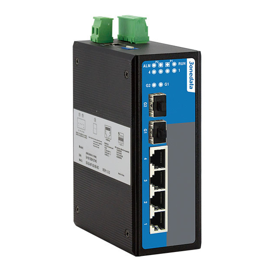
Page 6: Chapter 2 Hardware Description
CHAPTER 2 HARDWARE DESCRIPTION 2.1 Panel design IES716-2GS back and front panel has 4 pieces 10/100M port and 2 pieces gigabit SFP port, each port working statues LED indicator, 2 pieces redundant power supply and 1 piece relay alarm output, the structure is as follows: 1、DIP switch... -
Page 7: Relay Connection
2.3 Relay connection The relay owns two contacts of the terminal block on the top pane of IES716-2GS series. It is used to detect both power failure and port failure. The two wires attached to contacts form an open circuit when: (1) IES716-2GS series has lost power supply from one of the DC power inputs. - Page 8 User manual 10Base-T /100Base-TX Ethernet port 10Base-T/100Base-TX Ethernet port is located on front panel and the type is RJ45. The pinout of RJ45 port connects to UTP or STP. The distance is not more than 100m. 100Mbps Ethernet connector takes 120Ωof UTP 5, 10Mbps Ethernet connector takes 120Ωof UTP 3, 4, 5. RJ45 port supports automatically MDI/MDI-X connection.
-
Page 9: Led Indicator
User manual 2.7 LED Indicator IES716-2GS LED indictor light on the front panel .the function of each LED is described in the table as below: System status LED Indicator Description P1 connection regularly PWR1 P1 Power supply have no connection or... - Page 10 User manual Wiring Requirements Cable laying need to meet the following requirements, 1. It is needed to check whether the type, quantity and specification of cable match the requirement before cable laying; 2. It is needed to check the cable is damaged or not, factory records and quality assurance booklet before cable laying;...
-
Page 11: Chapter 3 Appearance And Dimension
User manual Chapter 3 Appearance and Dimension 3.1 Appearance IES716-2GS 3.2 Dimension Unit:mm Page 11... -
Page 12: Chapter 4 Packling List
Please check the packaging and accessories by your first using. Please inform us or our distributor if your equipments have been damaged or lost any accessories, we will try our best to satisfy you. Description Quantity 3onedata Industrial Ethernet switch User manual Warranty card Certificate of quality Page 12... -
Page 13: Chapter 5 Network Configuration
PC must be in the same Local Area Network. You can modify PC's or IES716-2GS series's IP address to make sure that they are in the same Local Area Network. Operating process can follow method 1 or method 2 as below, Method 1: Modify PC's IP address Click Start->Control panel->network connections->Local area Connection->Properties->Internet... -
Page 14: Chapter 6 Web Management
User manual CHAPTER 6 WEB MANAGEMENT IES716-2GS series have WEB server inside, can manage and maintenance the device very intuitive through WEB interface 6.1 Configurate preparing 1. The lowest requirement for user's computer is as below: Install operating system (Windows XP/2000,etc) ... -
Page 15: System Status
User manual Menu Introduction: Main Menu Function Display device information and port information such System Status System information as software version, IP address, etc. Display and configure information of each port: such as Port settings connection status, configuration modes, flow status etc. Port Configuration Bandwidth Set the maximum rate of the input/output packets for... - Page 16 User manual (Figure 6.2.1) Configuration Items Description Network mark of the device. It is convenient for management tools to Name judge. Serial No. Serial number of the device. It is convenient for device management. Description Description of the product features. Contact Information Contact information of the operator for device maintenance.
-
Page 17: Port Configuration
User manual Port 1-G2,if the port is connected properly the status should be LINK, no connection status will be LOS. 6.3 Port Configuration 6.3.1 Port Settings The port configuration interface mainly include port type(Electric port or optical port), setup speed mode and duplex mode,flow control. -
Page 18: Bandwidth Management
User manual 100M uses 100Base-TX standard and UTP/STP cable for connection. When the port is in 100M speed, Link/Act indicator will blink continuously while data transmitting. 100M fiber port uses 100Base- FX standard and single/multi-mode fiber for connection. Main fiber of 100Base-FX standard includes: 62.5nm multi-mode fiber and 50nm multi-mode fiber.Auto-negotiation includes 2 kinds of speed according the capability of the other end: 10M and 100M. - Page 19 User manual (Figure 6.3.2) Ingress Bandwidth Configuration: Ingress bandwidth limit includes 4 kinds: 1 All frames; 2 Broadcast&Multicast &unicast frames; 3 Broadcast&Multicast only; 4 Broadcast only “----” stands for no limitation, the rate of low priority queues (L)can be setted:128k, 256k, 512k, 1M, 2M, 4M, 8M.The rate of normal priority queues(N)...
-
Page 20: L2 Features
6.4 L2 Features 6.4.1 VLAN IES716-2GS supports based on 802.1Q VLAN. It deals with messages based on Tag of recognized message(including 802.1p priority and VLAN ID, etc.). Frames with 802.1q add 4 byte Tag based on Ethernet frames, including 2 byte TPID, 3 byte Priority, 1 byte CFI and 12 byte VLAN ID. - Page 21 User manual 2. Deal with transmit and receive message Receive message Type Message did not take Tag Message take Tag Put the VLAN tag point to Port Put the VLAN tag point to Port Access default VLAN ID for message default VLAN ID for message Put the VLAN tag point to Port Keep up VLAN ID, no need...
- Page 22 User manual (Figure 6.4.1) We can know as the figure, the type of port G1, G2 is Trunk, can allow the data of VLAN 1 and VLAN 2 pass. 5. Modify VLAN It can re-configure existing VLAN including modifying member’s type and quantity of the port. Steps are as follows: 1.
- Page 23 User manual 7. VLAN Configuration of Single Ring 1. Need to set one port as managed port, managed port and CPU port must in a same VLAN, figure as 6.4.4, port 1 is managed port. 2. The port that already set in ring network port, the VLAN port type must Trunk and take Tag, figure as 6.4.4.
-
Page 24: Igmp Snooping
User manual (Figure 6.4.5) : IES716-2GS series VLAN maximum support 64 VLAN item, VID value range:1~4095 Manged port is the port that manage and configure switch, it must in a same VLAN as CPU port 6.4.2 IGMP snooping IP host applies to join (or leave) multicast group to the neighboring router through IGMP (Internet Group Management Protocol) protocol. -
Page 25: Static Multicast Fwd
User manual (Figure 6.4.6) 1. Must configure the VLAN of 802.1q at first, then open IGMP Snooping function 2. Please do not open more IGMP snooping, waste source. 6.4.3 Static Multicast FWD The device provides the function of static MAC address forwarding. The destination address includes the data packets with static MAC address which will be transferred to the appointed port. -
Page 26: Qos
User manual none multicast address did not allow to add in this table and the format must according to XX-XX-XX- XX-XX-XX, did not have space or other illegal character, otherwise, will be display warning information. 1. This function has great impact on forwarding multicast, unless you can make sure the address is no problem, otherwise, please use it with caution. -
Page 27: Dscp
User manual 802.1p, there is no standard or amendment by that name published by the IEEE. Rather the technique is incorporated into IEEE 802.1Q standard which specifies the tag inserted into an Ethernet frame. Priority levels Eight different classes of service are available as expressed through the 3-bit PCP field in an IEEE 802.1Q header added to the frame. -
Page 28: Redundancy
User manual 1. Port priority is the highest level, don't need to check other QoS attributes is discharged into the highest priority queue if you set the port priority as 1. 2. DSCP priority comes second, unless we do not set DSCP, therefore will check 802.1p priority, otherwise it will line up according to the DSCP settings. -
Page 29: Rapid Ring
20ms. SW-Ring is the patented technology of 3onedata Co., Ltd. designed for industrial control network requiring high reliability. SW-Ring technology support maximum 250 pieces switches, in which the SW-Ring its self- recovery time is <20ms. - Page 30 User manual ms. Its main purpose is to detect network connection. It sends a detecting packet to next door devices by CPU. If they receive it, then reply a confirm packet to ensure network connection is active. If this setting will influence self-recovery time, we suggest advanced users can use it. Basic interface of Rapid Ring as shown in figure 6.6.2: (Figure 6.6.2)...
- Page 31 User manual (Figure 6.5.4) 3, Select “Apply”. 1. Method to enabled Ring V2 1. Enable Ring V2,Select Ring V2 in [Settings] drop-down menu, figure as 6.6.3 (Figure 6.6.3) 2. Enable ring group 1(or group 2), input network ID (support 0-255 pure digital), select the ring port in ring port 1 and ring port 2, figure as 6.6.4.
- Page 32 User manual (Figure 6.6.4) Ring V2 can also set Hello_time . Hello_time setting is time interval of sending detecting packet to network at regular time. The unit is ms. Its main purpose is to detect network connection. This setting will influence self-recovery time, we suggest advanced user use it. 2.
- Page 33 User manual (Figure 6.6.6) 3. Set 100, 101 device’s ring port as port 1 and port 2 in ring group 1, network ID:2, type: single ring. Set ring port as port 3 in ring group 2 , network ID: 3, type: coupling ring, figure as 6.6.7. (Figure 6.6.7)...
- Page 34 User manual (Figure 6.6.8) Method to enable Ring V3 1. Enable Ring V3,Select Ring V3 in [Settings] drop-down menu, figure as 6.6.9 (Figure 6.6.9) 2. After select Ring V3, Configuration interface is as figure 6.6.10, we can see Ring V3 support 4 different ring group: Single, Coupling, Chain and Dual_homing.
- Page 35 User manual (Figure 6.6.10) 3. Enable Ring Group 1(or Group 2), and enter into Network ID(support 0-255 number only).Select Ring Port between Port 1 and Port 2. “Chain” refers to strengthen user’s capability of making any type of redundant topological structure with flexibility by taking an advanced software technology.
- Page 36 User manual (Figure 6.6.12) 3. Set 100, 101 device’s ring port as port 3 and port 4 in ring group 1, network ID:2, type: single ring. Set ring port as port 1 in ring group 2 , Coupling ctrl port: 4, network ID: 3, type: coupling ring, figure as 6.6.13.
-
Page 37: Rstp
User manual Ring Ports in Ring Group 2, Network ID is 2. Ring Type is Chain; as shown in figure 6.6.16. (Figure 6.6.15) (Figure 6.6.16) 3. Use a wire to connect Port 1 and 2 of Device 107-109 in turn to make a chain. Use a wire to connect Port 1 and 2 of Device 100-103 in turn to make a Single Ring, Then use a wire to connect Port 2 of Device 107 and Port 1 of Device 109 to normal port of Device 102 and 103. - Page 38 User manual behaviors and bridge port roles to do this. RSTP was designed to be backwards-compatible with standard STP. While STP can take 30 to 50 seconds to respond to a topology change, RSTP is typically able to respond to changes within 3 × Hello times (default: 3 times 2 seconds) or within a few milliseconds of a physical link failure.
-
Page 39: Access Profile
User manual Forwarding delay:the port state of switch remain a forward delay time over the listening and learning. The maximum aging time:after one switch receive a packet from other switches , how long the packet is valid The port concepts of RSTP: Port path overhead:port link cost compared with port priority and port ID . - Page 40 User manual Password: Visitor use password, user authority allows the letter combination no more than 16 bytes Confirm password Make sure the last time input password is correct. (Figure 6.7.1) Page 40...
-
Page 41: Remote Monitoring
Community name with Write privilege can configure the device. 3. Setup appointed basic visit control list of the community name. IES716-2GS series supports SNMP V1/V2c. Both SNMP V1 and V2c use public character strings for match authentication. -
Page 42: Relay Alarm
Relay will be in open status. Power alarm IES716-2GS series provided dual DC power supply (AC power supply did not have alarm), if one power supply had problem, another will support power supply immediately, dual power supply hot back-up. Select to enable power alarm, If power supply was in unusual status, device will send alarm signal, inform power supply work unusual. -
Page 43: Traffic Statistics
User manual (Figure 6.8.2) In default status, the type of relay output is open, the alarm light is OFF, have no alarm, relay alway open. When the device have alarm, the light is ON, relay close Traffic Statistics The function of traffic Statistics is to calculate the data packets in a fixed time, included transmit and receive data packets. -
Page 44: Tx Frame Statistics
User manual Number of frames between128 and 255 bytes In255Octets (including invalid frames) Number of frames between 256 and 511 bytes In511Octets (including invalid frames) Number of frames between 512 and 1023 bytes In1023Octets (including invalid frames) Number of 1024-1518 or 1522 bytes(802.1Q) InMaxOctets (including invalid frames) Invalid oversized frames received (more than 1518... -
Page 45: Basic Settings
User manual Port mirroring refers to copy data from the port which need to be monitored to appointed monitoring port for analysis and monitoring. Ethernet switch supports many-for-one mirror which means messages from several ports can be copied to a monitored port. User can appoint the direction of monitored message, such as only monitoring of transmitted messages of appointed port. - Page 46 User manual Network type Address range Available IP network range 0.0.0.0~126.255.255.255 1.0.0.0~126.0.0.0 128.0.0.0~191.255.255.255 128.0.0.0~191.254.0.0 192.0.0.0~223.255.255.255 192.0.0.0~223.255.254.0 224.0.0.0~239.255.255.255 240.0.0.0~246.255.255.255 Others 255.255.255.255 255.255.255.255 A, B, C class address is unicast address; D class address is multicast address; E class address is reserved to prepare for the future for special purposes. Each IP address is represented as four decimal integers separated by IP address using dotted decimal.
-
Page 47: System Identification
In System Identification interface we can see Model, Name, Description, Serial NO., and Contact Information. We can modify these above items by this function. It will take effect after system reboot. Figure 6.11.2 is initial device settings of IES716-2GS series switch. Page 47... -
Page 48: System File Upgrade
User manual (Figure 6.11.2) Name To give a name to each device, length is not more than 16 bytes. Description A brief description to a device, the length is not more than 16 bytes. Serial No. Display Installation Location of the device, the length is not more than 30 bytes. 6.11.3 System File Upgrade The menu included 5 functions: Factory default, Device reboot, Download Configuration, up load configuration, upgrade firmware. - Page 49 User manual 1. Factory Default If you know the IP address of the device, user name and password: Use IE to login Web interface. Click "System Management" Click "System File Update" Choose "Factory Default" Click "OK" Notice: the IP address will be "192.168.1.254". Open a new interface, input "192.168.1.254"...
- Page 50 User manual If you know the IP address of the device, user name and password: Use IE to login Web interface. Click "System Management" Click "System File Update" Choose "Upgrade Firmware" Click "Browse" and find the place of uploading the file. Click "Upgrade"...
-
Page 51: Chapter 7 Repair And Service
Make a call to our technical office. Return or replace product. 7.1 Internet Service Please visit http://www.3onedata.com 7.2 Make a call to our technical office You can call our technical support office, the company has professional technical engineers to answer your questions and help you resolve your problems at the first time. -
Page 52: Appendix 1 Glossary Table
User manual Appendix 1 Glossary table Glossary Description ARP (Address An IP address to physical address protocol Resolution Protocol) Auto-Negotiation Switches at both ends of the device in accordance with the maximum performance to auto-negotiate the speed and duplex mode Broadcast Storm A port send excessive broadcast frame meantime on the network, accumulate the respond to send messages on the network ,... -
Page 53: Appendix 2 Default Factory
User manual Protocol) UTP(Unshielded Not shielded media out of twisted pair Twisted Pair) Appendix 2 Default factory Main Menu Function Main Menu Name IndustrialSwitch Module ManagedSwitch System System Desription 6Port status information Serial No. Contact information Port enable Enable Port Speed mode Consult automatic configuration... -
Page 54: Appendix 3 Treatment Of Common Problem
User manual Appendix 3 Treatment of common problem 1. Why the page is not normal when configured by a web browser? Before the access to WEB interface, please clear the IE cache and cookies. Otherwise, the WEB interface may be not normal. 2.
Need help?
Do you have a question about the IES716-2GS and is the answer not in the manual?
Questions and answers