Table of Contents
Advertisement
Quick Links
Advertisement
Table of Contents

Related Manuals for Emerson Liebert APM 15-90kVA


Summary of Contents for Emerson Liebert APM 15-90kVA
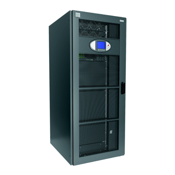
- Page 1 Liebert ® ™ User Manual–15-90kVA, 120, 208, 480 and 600V, 50/60Hz...
-
Page 3: Table Of Contents
TABLE OF CONTENTS ..........1 MPORTANT AFETY NSTRUCTIONS... - Page 4 Dry Contacts ............. . . 34 3.4.1 Input Dry Contacts.
- Page 5 ..........62 NSTALLATION RAWINGS LOT ®...
- Page 6 10.3 UPS Battery Start ............102 10.4 Switching the UPS from Normal Operation to Maintenance Bypass .
- Page 7 FIGURES Figure 1 Cabinet arrangement ............13 Figure 2 Liebert FlexPower assembly indicators and controls .
- Page 8 Figure 49 UPS dimensions continued, center of gravity—side, top and bottom views ....63 Figure 50 Liebert APM with top fan kit ............64 Figure 51 UPS main components—typical unit .
- Page 9 TABLES Table 1 Battery voltage, nominal and float ..........7 Table 2 Battery retorque values .
- Page 10 Table 50 Inverter output to critical load ........... . 121 Table 51 Component service life .
-
Page 11: Important Safety Instructions
MPORTANT AFETY NSTRUCTIONS SAVE THESE INSTRUCTIONS This manual contains important instructions that should be followed during installation of the Liebert APM, Liebert Bypass Distribution Cabinet ™ and batteries (where applicable). Read this manual thoroughly, paying special attention to the sections that apply to your installation, before working with the UPS. - Page 12 Ground Leakage Currents CAUTION Risk of electric shock from high leakage current. Can cause injury, property damage and death. EARTH CONNECTION IS ESSENTIAL BEFORE CONNECTING THE INPUT SUPPLY. Earth leakage current exceeds 3.5 mA and is less than 1000 mA. Transient and steady-state earth leakage currents, which may occur when starting the equipment, should be taken into account when selecting instantaneous RCCB or RCD devices.
- Page 13 Battery Cabinet Precautions The following warning applies to all battery cabinets supplied with UPS systems. Additional warnings and cautions applicable to battery cabinets may be found in 5.0 - Battery Installation. WARNING Risk of improper handling. Can cause injury, property damage and death. Internal battery strapping must be verified by manufacturer prior to moving a battery cabinet (after initial installation).
-
Page 14: Glossary Of Symbols
LOSSARY OF YMBOLS Risk of electrical shock Indicates caution followed by important instructions AC input AC output Requests the user to consult the manual Indicates the unit contains a valve-regulated lead acid battery PbH2SO4 Recycle DC voltage AC voltage Equipment grounding conductor Bonded to ground ®... -
Page 15: Introduction
Introduction NTRODUCTION The Liebert APM UPS is a transformer-free, hardware-scalable, online uninterruptible power system with 208/120V input and 208/120V output capability. The Liebert APM can operate with either a 50 or 60Hz input and provide a matching output frequency conversion. The rack-mounted 15kVA/kW modules allow scaling the UPS’s capacity in 15kVA increments from 15kVA to a maximum of 90kVA in a single frame. - Page 16 Introduction WARNING Risk of electrical shock and high short circuit current. Can cause equipment damage, personal injury and death. The following precautions must be observed when working on batteries: • Remove watches, rings and other metal objects. • Use tools with insulated handles. •...
-
Page 17: Table 1 Battery Voltage, Nominal And Float
Introduction Matching Battery Cabinets—Optional Although the individual battery cells are sealed (valve-regulated) and require only minimal maintenance, the Battery Cabinets should be given a periodic inspection and electrical check. Checks should be performed at least annually to ensure years of trouble-free service. Voltage Records: With the Battery Cabinet DC circuit breaker closed and the connected UPS operating, measure and record battery float voltage. -
Page 18: Installation
Installation NSTALLATION This section describes the Liebert APM’s environmental requirements and mechanical considerations that must be taken into account when planning the positioning and cabling of the UPS equipment. Because each site is unique, this section presents a guide to general procedures and practices that should be observed by the installing engineer, rather than step-by-step installation instructions. -
Page 19: Initial Inspections
2. Compare the contents of the shipment with the bill of lading. Report any missing items to the carrier and your local Emerson representative immediately. 3. Check the product label on the back of front door and confirm the contents match the UPS model, capacity and main parameters that were ordered. -
Page 20: Environmental Considerations
Installation 2.3.2 Environmental Considerations Before installing the Liebert APM, verify that the UPS room satisfies the environmental conditions stipulated in 11.2 - UPS Environmental, paying particular attention to the ambient temperature and air exchange system. The UPS unit should be installed in a cool, dry, clean-air environment with adequate ventilation to keep the ambient temperature within the specified operating range 32°F to 104°F (0°C to 40°C). -
Page 21: Mechanical Considerations
Leave a minimum of 24 in. (610mm) between the top of the UPS frame and the ceiling to permit adequate air circulation above the unit. Emerson recommends against using air conditioning or other systems that blow air onto the top of the unit. -
Page 22: Special Considerations For Parallel Systems
When bringing the 1+N system online for the first time or after removing one unit, Emerson recommends checking the bypass current mismatch. To check the bypass current mismatch: 1. -
Page 23: Optional Cabinets
Installation 2.6.1 Optional Cabinets If the Liebert APM installation includes a Liebert BDC, the UPS must be positioned to allow the Liebert BDC to be bolted to right side of the Liebert APM (see Figure 1). The Liebert BDC must be cabled and bolted to the Liebert APM before the UPS and bypass cabinet are moved into their final position. -
Page 24: Liebert Flexpower ™ Assembly
Installation ™ Liebert FlexPower Assembly Figure 2 Liebert FlexPower assembly indicators and controls Fault LED Run LED DIP Switches Battery Start Button Ready Switch The Battery start button allows starting of UPS on battery; refer to 10.3 - UPS Battery Start. The Run LED is illuminated Green when the Liebert FlexPower assembly is operating normally. -
Page 25: Electrical Connections -Ups
Electrical Connections—UPS —UPS LECTRICAL ONNECTIONS The UPS requires both power and control cabling once it has been mechanically installed. All control cables must run separate from power cables in metal conduits or metal ducts that are electrically bonded to the metalwork of the cabinets to which they are connected. WARNING Risk of electric shock. -
Page 26: Rectifier And Bypass Input Supply Of The Ups
Electrical Connections—UPS 3.2.1 Rectifier and Bypass Input Supply of the UPS Overcurrents Install suitable protective devices in the distribution unit of the incoming mains supply, considering the power cable current-carrying capacity and overload capacity of the system. Generally, the magnetic circuit breaker with IEC60947-2 tripping curve C (normal) at the 125% of the nominal current listed in Table 41 is recommended. -
Page 27: Ups Input Configuration
Electrical Connections—UPS 3.2.4 UPS Input Configuration By default, the Liebert APM ships with internal links installed between the bypass input and main (rectifier) input (single input configuration see Figure 84). Figure 4 shows the Liebert APM in a split bypass (single source dual-input) configuration. In this configuration, the static bypass and the maintenance bypass lines are supplied by the same source using separate feeds. -
Page 28: Ups Input Configuration With Transformers
Electrical Connections—UPS 3.2.5 UPS Input Configuration with Transformers Figure 5 shows the Liebert APM in a split bypass (single-source, dual-input) configuration using two transformers. One transformer is inside the Bypass Distribution Cabinet and the other inside the UPS. In this configuration, the static bypass and the maintenance bypass lines are supplied by the same source using separate feeds. -
Page 29: Figure 6 Control Wiring For The Dual Input Transformer Configuration
Electrical Connections—UPS Figure 6 Control wiring for the dual input transformer configuration The external maintenance bypass is available with a 480V, 600V or 208V optional internal transformer. Each UPS frame size (45kVA or 90 kVA) is available with a 480V, 600V or 208V optional internal transformer. -
Page 30: Cabling Guidelines
Electrical Connections—UPS 3.2.6 Cabling Guidelines The following are guidelines only and are superseded by local regulations and codes of practice where applicable. Use wiring rated at 75°C or greater. 1. Take special care when determining the size of the neutral cable, as current circulating on the neutral cable may be greater than nominal current in the case of non-linear loads. -
Page 31: Figure 7 Input Busbars-Liebert Apm 45Kva Frame
Electrical Connections—UPS Figure 7 Input busbars—Liebert APM 45kVA frame 1.75" (44mm) 1.52" (39mm) (Typ.) 1.75" (44mm) (Typ.) 1.65" ø .55" (14mm) ø .50" (13mm) (42mm) 1.65" 4 places 2 places (42mm) .8" (20mm) 3.54" (90mm) (Typ.) .8" (20mm) 1.6" (41mm) .7"... -
Page 32: Figure 8 Input Busbars-Liebert Apm 90Kva Frame
1. Dimensions are in inches [mm]. UAM02021 2. Control wiring and power wiring must be run in separate conduits. Rev. 3 3. Emerson recommends using only copper cables. 4. All wiring must be in accordance with national and local electrical codes. ® ™... -
Page 33: Figure 9 Liebert Bdc
3. Only copper cables are recommended. 4. All wiring is to be in accordance with national and local electrical codes. 5. If bypass distribution cabinet is attached to the UPS, Emerson will supply the TOP VIEW interconnection cables. 6. See UAM06020B, Pg. 2 of 2. -
Page 34: Figure 10 Busbars-Liebert Bdc
Electrical Connections—UPS Figure 10 Busbars—Liebert BDC UPS Bus Ø .44" (11mm) Neutral Bus Typical 5" x 8.9" (127 x 227mm) Ø .44" 1.75" System (11mm) (44.5mm) Input Bus Typical Typical See Detail B Busbars Ø .56" 1.38" (35mm) 1.38" (35mm) (14mm) Typical 1.38"... -
Page 35: Figure 11 Busbars-External 600Mm Battery Cabinet
2. Control wiring and power wiring must be run in separate conduits. 3. Copper cables onlyare recommended. UAM05020 4. All wiring is to be in accordance with national and local electrical codes. Rev. 1 5. If battery cabinet is attached to UPS, Emerson will supply interconnect cables. ® ™ Liebert... -
Page 36: Accessory Fuses And Backfeed Breaker Wiring
3. Emerson recommends using only copper cables. 4. All wiring must be in accordance with national and local electrical codes. UAM05022 5. If the battery cabinet is attached to the UPS, Emerson will supply the interconnect cables. Rev. 0 3.2.8 Accessory Fuses and Backfeed Breaker Wiring Two fuse blocks provide power for the backfeed breakers (standard) and the BDSi (optional). -
Page 37: Figure 13 Accessory Fuses
Electrical Connections—UPS Figure 13 Accessory fuses BDSi Fuse Backfeed Block Breaker (optional) Fuse Block Figure 14 Dual input backfeed breaker wiring when bypass distribution cabinet not used Upstream Bypass 1. Auxiliary contacts not needed for backfeed breaker operation. 2. A 120V shunt trip coil is required for proper operation. Input Breaker Upstream System Dual Input Control Wiring... -
Page 38: Safety Ground
Electrical Connections—UPS 3.2.9 Safety Ground The safety ground busbar is below the neutral input and output busbars as shown in Figure 15 below. The safety ground cable must be connected to the ground busbar and bonded to each cabinet in the system. -
Page 39: Figure 15 Ground And Neutral Busbar Connections-45Kva Frame Busbars
Electrical Connections—UPS Figure 15 Ground and neutral busbar connections—45kVA frame busbars 1.75" (44mm) 1.52" (39mm) (Typ.) 1.75" (44mm) (Typ.) 1.65" ø .55" (14mm) ø .50" (13mm) (42mm) 1.65" 4 places 2 places (42mm) .8" (20mm) 3.54" (90mm) (Typ.) .8" (20mm) 1.6"... -
Page 40: Figure 16 Ground And Neutral Busbar Connections-90Kva Frame Busbars
1. Dimensions are in inches [mm]. UAM02021 2. Control wiring and power wiring must be run in separate conduits. Rev. 3 3. Emerson recommends using only copper cables. 4. All wiring must be in accordance with national and local electrical codes. ® ™... -
Page 41: Protective Devices
3.2.11 Cabling Procedure CAUTION The operations described in this section must be performed by authorized electricians or qualified technical personnel. If you have any difficulties, contact your local Emerson representative or Liebert Services. NOTE Hydraulic pressure pliers, combinative tools and piston ring pliers should be used to connect AC wiring. -
Page 42: Control Cables Details
Risk of electrical shock and arc flash. Can cause property damage, injury and death. The DC bus is live when this internal battery connection is made. This connection is to be performed ONLY by Emerson Network Power ® Liebert Services at startup. -
Page 43: Figure 17 Static Bypass Assembly Connections To Display Cabinet And Options
Electrical Connections—UPS Figure 17 Static bypass assembly connections to display cabinet and options Monitor Operator Control Panel Battery Cabinet Bypass Distribution Cabinet Static Bypass Backfeed Protection Bypass Assembly Mains Backfeed Protection Temp Sensor (optional) and BCB Control Board Ground Fault (optional) Sensor &... -
Page 44: Dry Contacts
Electrical Connections—UPS Dry Contacts The UPS provides input dry contacts and output dry contacts on the Auxiliary Terminal Block (ATB). 3.4.1 Input Dry Contacts External input dry contacts are connected via the ATB. Dry contacts are available for environment detection, battery ground fault detection, etc. The UPS accepts external signal from zero-voltage (dry) contacts connected through external dry contact terminals produced, and these terminals are on the static bypass assembly. -
Page 45: Output Dry Contacts
Electrical Connections—UPS 3.4.2 Output Dry Contacts The Auxiliary Terminal Block has three output dry contact relays (see Figure 20 and Table 5). Figure 20 Output dry contacts and EPO wiring NOTE: The black square () on each connector indicates Pin 1. Refer to Figure 18 for the location of connectors J10, J11 and J12. -
Page 46: Battery Cabinet Interface Connectors
Electrical Connections—UPS 3.4.4 Battery Cabinet Interface Connectors The battery cabinet interface is on the Auxiliary Terminal Block at J8 and J4. Refer to Figure 18 for the location of connectors J4 and J8 and to Figure 19 for circuit details. Table 7 Battery cabinet interface Name... -
Page 47: Figure 22 Single Ups Remote Emergency Power Off
Electrical Connections—UPS Table 8 EPO input contact relays Position Name Description J6.1 EPO_NC EPO Activated when opened to J6.2 J6.2 +12V EPO Activated when opened to J6.1 J6.3 +12V EPO Activated when shorted to J6.4 J6.4 EPO_NO EPO Activated when shorted to J6.3 NOTE The Emergency Stop action within the UPS shuts down the rectifier, inverter and static bypass. -
Page 48: Parallel System And Lbs System Installation
WARNING To achieve coordinated operation of the modules in the parallel system, it is required to configure each module separately using Emerson configuration software. This must be done by Emerson service personnel. 4.2.2 Cabinet Installation Position the UPS modules and make connections as shown in Figure 23. -
Page 49: External Protective Device
UAM4002A,B D) NOTE For parallel system installations, an external bypass rated for the total system load must be installed. For parallel systems, Emerson recommends installing bypass load sharing inductors to optimize current sharing during static bypass operation. 4.2.3 External Protective Device Refer to 3.2 - External Protective Devices. -
Page 50: Power Cable
Parallel System and LBS System Installation 4.2.4 Power Cable The power cable wiring is similar to that of the UPS module. Refer to 3.1 - Power Cabling. The bypass and rectifier input supplies must use the same neutral line input terminal. If the input has a current leakage protective device, the current leakage protective device must be fitted upstream of the neutral line input terminal. -
Page 51: Parallel Cables
Parallel System and LBS System Installation Figure 25 Output breaker control wiring Buyout Liebert APM Paralleling Switchboard System AC Output AC Input 4-Wire + GND 4-Wire + GND See Note 2 MOB1 UHRF3S67X2 (J5) Liebert APM #1 See Note 3 X2 J5 MOB2 Liebert... -
Page 52: Key Interlock System
Parallel System and LBS System Installation 4.2.8 Key Interlock System Figure 27 Key interlock system control wiring Buyout Liebert APM Paralleling Switchboard AC Input AC Output Ø A ØA Ø B Ø B Ø C Ø C See Note 2 UHRF3S67X2 (J5, J12) Kirk Key MOB1... -
Page 53: Remote Epo
Parallel System and LBS System Installation Figure 28 Locations of ports J1, J2 and J3 on bypass module Input/output dry contact and EPO/BCB/MBC interface J1 ~ J3 port can’t connect to phone! INTELLISLOT1 INTELLISLOT2 INTELLISLOT3 PARA PARA MONITOR RS485-1 RS485-2 RS232 4.2.9 Remote EPO... -
Page 54: Lbs System
Parallel System and LBS System Installation LBS System 4.3.1 Cabinet Installation A dual bus system consists of two independent UPS systems, each containing one or more parallel UPS modules, as shown in Figure 30. The dual bus system has high reliability and is suitable for loads with multiple input terminals. -
Page 55: Figure 31 Connection Of Typical Dual Bus System Of Two Parallel Systems
Parallel System and LBS System Installation Figure 31 Connection of typical dual bus system of two parallel systems UPS 1 UPS 2 UPS 3 UPS 4 Bypass Module Bypass Module Bypass Module Bypass Module LBS Cable LBS Cable Figure 32 Connection of typical dual bus system of two single UPS’s without redundant LBS cable UPS 1 UPS 2 Bypass Module... -
Page 56: Battery Installation
NSTALLATION Introduction Emerson recommends that the batteries in external cabinets be the same type and made by the same manufacturer as the internal batteries in the Liebert APM. If multiple sets of batteries connected in parallel are used to provide the required battery backup run times, fit each set with an isolating device to permit working on one of the battery sets while leaving the others in service and providing backup protection. -
Page 57: Ups Batteries-Liebert Apm 45Kva Frame Only
Battery Installation UPS Batteries—Liebert APM 45kVA Frame Only The Liebert APM’s internal batteries are fully charged before the unit is shipped. During storage and transportation, some charge is lost. All batteries should be recharged before use. The battery charger works only when the Liebert APM is connected to input power and turned On. NOTE Full safety instructions concerning the use and maintenance of UPS batteries are provided in the appropriate battery manufacturer's manuals, available on the manufacturer’s Web site. -
Page 58: Figure 35 Internal Battery Control Wiring
Battery Installation Figure 35 Internal battery control wiring Battery Breaker Liebert APM DC Bus Positive (+) Neutral (Neg. Midpoint) Neg. Midpoint Negative (-) Liebert APM Aux. Internal Battery X107 Black Black Black X101 Detail A Capacitor Black See Note 2 Board Board Striped Com... -
Page 59: External Battery Cabinet Installation
Web site. When replacing batteries, Emerson recommends that the batteries in external cabinets be the same type used internally in the Liebert APM. See Tables 38 and 40 for batteries that are approved for use with the Liebert APM. -
Page 60: Connecting The Batteries
Battery Installation 5.4.2 Connecting the Batteries If the Liebert APM battery cabinets are installed on a raised floor, the battery power cables and circuit breaker control cables may be routed to the UPS cabinet through the bottom of the cabinet. If the Liebert APM battery cabinets are installed adjacent to one another on a solid floor, these cables may be passed between the cabinets through slots in the lower sides of the cabinets. -
Page 61: Figure 38 Battery Trays For 600Mm Battery Cabinet
Battery Installation Figure 38 Battery trays for 600mm battery cabinet HX300 HX330 HX205 HX150 ® ™ Liebert... -
Page 62: Figure 39 Battery Cabinet With Trays For 900Mm Battery Cabinet
Battery Installation Figure 39 Battery cabinet with trays for 900mm battery cabinet ® ™ Liebert... -
Page 63: Installation Considerations
Battery Installation 5.4.3 Installation Considerations Position—Liebert battery cabinets come in versions specific to the left side of the UPS. If the system includes a matching Liebert BDC, the cabinet should be mounted to the right of the UPS (nearest the busbars) and the battery cabinet(s) should be installed to the left of the UPS. -
Page 64: Figure 40 Battery Cabinet Connection To Liebert Apm
Battery Installation Table 9 Control wiring for Liebert APM to battery cabinet From Liebert APM UPS Bypass Battery Cabinet Module (X2 J4 & J8) Terminal Strip (TB1) J4-2 TB1-12 J4-3 TB1-11 J4-4 TB1-10 J8-1 TB1-6 J8-2 TB1-7 J8-3 TB1-8 J8-4 TB1-9 Figure 40 Battery cabinet connection to Liebert APM AC 120V... -
Page 65: Non-Standard Batteries
When batteries other than a matching battery cabinet are used, a remote battery disconnect switch with overcurrent protection is required per the National Electrical Code. Contact your local Emerson sales representative about this option. Refer to Figures 87 and 88 for details. -
Page 66: Figure 42 Control Wiring Diagram For Battery Ground Fault Detection Option
Battery Installation Figure 42 Control wiring diagram for battery ground fault detection option W600 UHRF3S67X2 (J9) UHR93S6A1ZA6 Output EMI Board Liebert APM Bypass Module Output A Output B Output C Output N X2_J4 UHRF3S67X2 UHW241M5 Auxiliary Power Board X2_J9 W603 W601 Liebert APM Bypass Module Battery... -
Page 67: Liebert Bdc
™ Liebert BDC ™ IEBERT The Liebert BDC is designed to operate in UPS normal mode, static bypass mode and maintenance mode. The Liebert BDC offers either 45kVA or 90kVA capacity to match the associated Liebert APM frame offerings. Each of the Liebert BDC capacities offer optional input 208V, 480V and 600V internal transformers as well as multiple output distribution selections. -
Page 68: Maintenance Mode
™ Liebert BDC Maintenance Mode When the Liebert BDC is in Maintenance mode (MBB closed; BIB/MIB open), it provides an alternate path for power to the connected equipment should the UPS need to be taken out of service for limited maintenance or repair. -
Page 69: Input/Output Wiring
™ Liebert BDC 6.5.3 Input/Output Wiring Follow the steps below to connect the input wiring: NOTE Input wiring must be installed using conduit if cabinet is not mounted to the immediate right of the UPS. 1. Locate the input wiring access (top or bottom access), remove the conduit landing plate and punch the appropriate size hole for the size conduit being used. -
Page 70: Figure 45 Bdc Connection To Liebert Apm
™ Liebert BDC Figure 45 BDC connection to Liebert APM Output Neutral ØA ØB Output ØC Utility Kirk Key K1 Kirk Key K2 AC Input Output Ground Fuses Ground to Unit Frame SKRU 1 2 3 4 5 6 7 8 9 10 11 12 Input Neutral Push Button... -
Page 71: Bolting Cabinets Together
™ Liebert BDC Bolting Cabinets Together NOTE UPS wiring must be completed before the cabinets are bolted together. 1. Line up cabinets so that mounting holes are aligned. Figure 46 Bolting Liebert APM to a Liebert BDC Washer Split, M10 3 Washer Hex Head Flat, M10... -
Page 72: Installation Drawings
Installation Drawings NSTALLATION RAWINGS The diagrams in this section illustrate the key mechanical and electrical characteristics of the Liebert APM UPS System cabinets (UPS, Liebert BDC and battery). Figure 47 UPS dimensions- front view 55.4" (1408mm) 23.8" (604mm) 1. All dimensions are in inches (mm). 2. -
Page 73: Figure 49 Ups Dimensions Continued, Center Of Gravity-Side, Top And Bottom Views
Installation Drawings Figure 49 UPS dimensions continued, center of gravity—side, top and bottom views 23.4" 3" (595mm) (77mm) See Detail A 9.2" Power 28.3" (235mm) Cable Entry (719mm) 21.26 x 7.87" Bracket (540 x 200mm) Centers Vent Screen 34.3" (871mm) Power Mechanical Caster... -
Page 74: Figure 50 Liebert Apm With Top Fan Kit
Installation Drawings Figure 50 Liebert APM with top fan kit Caster Mechanical Stop DETAIL A 23.4" 3" FRONT (595mm) (77mm) Top Fan 20.7" (526mm) See Detail A Flange to Flange 9.2" Power Cable Entry 13.2" 28.3" 12.1" (235mm) 21.26" x 7.87 (335mm) (718mm) (308mm) -
Page 75: Table 11 Center Of Gravity And Weights For Liebert Apm 90 Kva Frame
Installation Drawings Table 11 Center of gravity and weights for Liebert APM 90 kVA frame Center of Gravity Weight, lb (kg) Dimension X Dimension Y Dimension Z KVA Rating in. (mm) in. (mm) in. (mm) Unit Shipping No Internal Options 16.65 (423) 37.64 (956) 18.78 (477) -
Page 76: Table 12
Installation Drawings Table 12 Center of gravity and weights for Liebert APM 90 kVA frame with top fan option Center of Gravity Weight, lb (kg) Dimension X Dimension Y Dimension Z KVA Rating in. (mm) in. (mm) in. (mm) Unit Shipping Top Fan Option Only 17.99 (457) -
Page 77: Table 14 Center Of Gravity And Weights For Liebert Apm 45 Kva Frame
Installation Drawings Table 13 Center of gravity and weights for Liebert APM 45 kVA frame Center of Gravity Weight, lb (kg) Dimension X Dimension Y Dimension Z kVA Rating in. (mm) in. (mm) in. (mm) Unit Shipping 12HX100 Batteries 14.29 (363) 31.50 (800) 21.30 (541) 1922 (874) -
Page 78: Figure 51 Ups Main Components-Typical Unit
Installation Drawings Figure 51 UPS main components—typical unit UAM02000 UAM02000 Liebert APM 45kVA Frame Rev. 2 Rev. 2 Liebert APM 90kVA Frame ® ™ Liebert... -
Page 79: Figure 52 Ups Cable Connections-45Kva And 90Kva Frames
Installation Drawings Figure 52 UPS cable connections—45kVA and 90kVA frames 45kVA frame 90kVA frame ® ™ Liebert... -
Page 80: Figure 53 Battery Cabinet Connection To Ups
1. Dimensions are in inches [mm]. UAM02021 2. Control wiring and power wiring must be run in separate conduits. Rev. 3 3. Emerson recommends using only copper cables. 4. All wiring must be in accordance with national and local electrical codes. ® ™... -
Page 81: Figure 54 Battery Cabinet Connection To Ups (Continued)
Installation Drawings Figure 54 Battery cabinet connection to UPS (continued) 600mm Battery Cabinet 900mm Battery Cabinet Table 15 Interconnect wiring for Liebert APM to battery cabinet From Conductors UPS Battery Busbar External Battery Cabinet Busbar Positive, DC Neutral, Negative UPS Static Bypass Assembly Battery Cabinet Terminal Block TB1 Battery Breaker Shunt and Aux Contacts J4 and J8... -
Page 82: Figure 55 Battery Cabinet Outline Drawing, Weights And Center Of Gravity, 600Mm Cabinet
Installation Drawings Figure 55 Battery cabinet outline drawing, weights and center of gravity, 600mm cabinet 3.75" (95mm) Cable Entry Area Outside Panel 8.2" x 8.7" (210 x 220mm) 2 Places FRONT Cable Entry Area 2.5" (65mm) 14.6" x 7.6" Outside Panel 7.9"... -
Page 83: Figure 56 Battery Cabinet Outline Drawing, Weights And Center Of Gravity 900Mm Cabinet
Installation Drawings Figure 56 Battery cabinet outline drawing, weights and center of gravity 900mm cabinet 4" (101mm) Outside Panel Cable Entry Area 14.6" x 7.6" 17.1" (434mm) (370 x 190mm) Outside Panel FRONT 7.5" (190mm) Outside Frame Cable Entry Area 8.2"... -
Page 84: Figure 57 Outline Drawing, Liebert Bdc For Liebert Apm, 15-45Kva
Installation Drawings Figure 57 Outline drawing, Liebert BDC for Liebert APM, 15-45kVA 11.5" Cable Entry Area (292mm) 23.6" 6.2" x 13.2" 39.5" (1000mm) Outside (600mm) (57 x 335mm) Panel Cable Entry Area Cable Entry Area 11.4" x 13.2" 11.4" x 13.2" 6.5"... -
Page 85: Figure 59 Liebert Bdc Connection To Ups
Corner Post Removed Rev. 0 NOTES 1. All Emerson-supplied cable must be repositioned prior to and while the cabinets are being placed in their final installed location. 2. All interconnection hardware supplied by Emerson. 3. AC connections must be made to the UPS module before attaching Liebert BDC to UPS module. -
Page 86: Figure 60 Acceptable Hardware Configuration For Torque Application
Installation Drawings Table 17 Interconnect wiring for Liebert APM to Liebert BDC From Conductors Utility AC source BDC System Input Bus Phase A, B, C Utility AC Source BDC System Input Bus Neutral BDC Bypass Isolation Breaker UPS Main Input Phase A, B, C BDC Bypass Isolation Breaker UPS Main Input... -
Page 87: Figure 61 Seismic Mounting Bracket Details
Installation Drawings Figure 61 Seismic mounting bracket details ® ™ Liebert... -
Page 88: Liebert Intellislot ® Installation
® Liebert IntelliSlot Installation ® IEBERT NTELLI NSTALLATION Liebert IntelliSlot Communication The Liebert APM has three Liebert IntelliSlot ports to allow installation of optional communication cards. Liebert IntelliSlot cards communicate via Liebert’s proprietary Velocity protocol to cards that translate the information into such protocols as SNMP and Modbus. Other cards provide dry contact signals for external signaling of operating status. -
Page 89: Liebert Intellislot Card Web Interface
Trellis ™ • IS-UNITY-DP: Offers a web interface to monitor and configure the Life.net and Emerson Network Power proprietary protocols for use with the Emerson Life Station, Liebert Nform and Emerson Trellis. It allows selection and configuration of two of the available third-party protocols—SNMP, Modbus or BACnet—for operation with building management systems. -
Page 90: Liebert Intellislot
® Liebert IntelliSlot Installation ® Liebert IntelliSlot Relay Card The Liebert IntelliSlot Relay card (IS-RELAY) provides voltage-free contact closures for remote monitoring of alarm conditions. Delivering On Battery, On Bypass, Low Battery, Summary Alarm, UPS Fault and On UPS signals, the easy-to-install card integrates with AS/400 computers (additional cable required) and other relay contact monitoring systems. -
Page 91: Liebert Intellislot ® Relay Card Jumper Setup
® Liebert IntelliSlot Installation ® 8.4.2 Liebert IntelliSlot Relay Card Jumper Setup The Liebert IntelliSlot Relay Card has five jumpers, P3 through P7, as shown in Figure 64. Each jumper connects two pins. Figure 64 Jumper location and numbering Front Card Jumper Jumper... -
Page 92: Liebert Intellislot ™ Multiport Card
The matching Liebert battery cabinets allow installing an optional Alber BDSi battery monitoring system inside the cabinet. The Alber BDSi by Emerson continuously checks all critical battery parameters, such as cell voltage, overall string voltage, current and temperature. Automatic periodic tests of internal resistance of each battery will verify the battery's operating integrity. -
Page 93: Figure 66 Alber Bdsi Controller And Input Connection
® Liebert IntelliSlot Installation Figure 66 Alber BDSi controller and input connection Rear Panel 120VAC 50/60Hz INPUT XXXXXXXXXXXXXAXA XXXXXXXXXXXA OUTPUT POWER X XXXXXXA Input ® ™ Liebert... -
Page 94: Battery Temperature Compensation
® Liebert IntelliSlot Installation Battery Temperature Compensation For a UPS with external batteries, an optional battery temperature interface optimizes the external battery management by connecting up to four external temperature sensors from the battery cabinets to a control unit inside the UPS. Figure 67 Multi-temperature sensors Temperature Sensor... -
Page 95: Operator Control And Display Panel
Operator Control and Display Panel PERATOR ONTROL AND ISPLAY ANEL Operator Control Panel The control panel and LCD on the front of the Liebert APM lets the operator: • Turn the UPS On or Off. • Transfer into the various operating modes. •... -
Page 96: Mimic Display Indicators
Operator Control and Display Panel Mimic Display Indicators Figure 69 Mimic display indicators location E ME R S O N Network Power Mimic indicators Mimic indicators 1. Rectifier indicator 1. Rectifier indicator 2. Battery indicator 2. Battery indicator 3. Bypass indicator 3. -
Page 97: Control Buttons
Operator Control and Display Panel Control Buttons The Control Buttons on the front panel may be used to shut down the UPS completely, turn the inverter on or off, restart the UPS after a fault and silence the alarm, as shown in Figure 70. The function of each button is described in Table 24. -
Page 98: Lcd Overview
Operator Control and Display Panel LCD Overview The LCD on the front panel has five main sections, as shown in Figure 72. Press the F1 key below the LCD to scroll through these sections. • UPS system information - view UPS name and model, date and time, overall status. •... -
Page 99: Navigation Keys
Operator Control and Display Panel Navigation Keys The navigation keys on the front panel—F1 through F4 and Help—are used to access the LCD to view the current status and other information about the Liebert APM. Navigation key icons on the LCD appear above each key to indicate its operation (see Table 25). The keys are “soft keys”... -
Page 100: Language Selection
Operator Control and Display Panel Figure 73 Menu tree Mains (input) Bypass Output Load System L-N voltage (V) L-N voltage (V) L-N voltage (V) Sout (kVA) Sout (kVA) L-N current (A) Frequency (Hz) L-N current (A) Pout (kW) Pout (kW) Frequency (Hz) L-L voltage (V) Frequency (Hz) -
Page 101: Current Date And Time
Operator Control and Display Panel Figure 74 Language selection screen Single APM 090 kVA 0 2 : 1 7 : 4 7 ENGLISH DEUTSCH POLSKI FRANCAIS ITALIANO ESPANOL NEDERLANDS SVENSKA PORTUGUES Language HELP Current Date and Time To change the system date and time: 1. -
Page 102: Ups History Log
Operator Control and Display Panel 9.10 UPS History Log The Liebert APM displays status changes as they occur and stores that data in the history log, as shown in Figure 76. • History Log: When a record moves to the history log, the time the status changed is recorded. The history log can hold up to 512 records. -
Page 103: Default Screen
Operator Control and Display Panel Figure 77 Opening display Single APM 090kVA 0 2 :1 7 : 4 7 EMERSON ™ Network Power Press any key back to main menu HELP 9.11.2 Default Screen After the UPS has powered up and completed a self-test, the output screen appears, as shown in Figure 78. -
Page 104: Screen Saver Window
It remains on the LCD for 2 minutes, then the screen will go dark. The LCD will become active again when any key is pressed. Figure 79 Screen saver window Single APM 090kVA 0 2 :1 7 : 4 7 EMERSON ™ Network Power Press any key back to main menu HELP HELP 9.12... -
Page 105: System Self-Test
Operator Control and Display Panel 9.12.3 System Self-Test When a system self-test is completed, a pop-up window reports the System Self-Test finished . results of the test, as shown at right. Please check the current • Press the Help (Enter) key and the pop-up window closes. warnings 9.12.4 Battery Capacity Test Confirmation When a battery capacity test is started from the Command menu, the... -
Page 106: Table 26 Ups Menus And Data Window Items
Operator Control and Display Panel Table 26 UPS menus and data window items Menu Type Item Type Explanation L-N voltage (V) Phase voltage L-N current (A) Phase current Mains Frequency (Hz) Input frequency (input) L-L voltage (V) Line-line voltage Power factor Power factor L-N voltage (V) Phase voltage... - Page 107 Operator Control and Display Panel Table 26 UPS menus and data window items (continued) Menu Type Item Type Explanation Display contrast Adjust the LCD display contrast Choose the format for date display: YYYY MM DD, DD MM YYYY and MM DD Date format set YYYY Date &...
-
Page 108: Operation
This unit refers to some modes and conditions that are set or adjusted using proprietary service software. To take advantage of all the available features for the Liebert APM, the unit must be commissioned by an Emerson-authorized engineer. Normal Mode Operating in normal mode, the Liebert APM’s rectifier derives power from a utility AC source and... - Page 109 0-30 days. As a module goes offline, another module comes online. Each module will rotate being online and offline. Sleep Mode must be enabled by an Emerson Customer Engineer. A minimum of three power modules are required for Sleep Mode to be activated. Once enabled, Sleep Mode requires no further action.
-
Page 110: Ups Startup
Operation Generator Mode The Liebert APM UPS can be set up for operation in Generator Mode by an Emerson Network Power Liebert Services engineer. The setup requires connecting J9 Pin 1 to Pin 4 or connecting J9 Pin 2 to Pin 4. -
Page 111: Startup In Eco Mode
Operation Table 28 Mimic indicators after initialization Status Rectifier Indicator Green Battery Indicator Bypass Indicator Green Inverter Indicator Load Indicator Green Status Indicator Amber 7. Ensure that the Liebert FlexPower assembly ready switches are latched (in Down position). 8. Close the external output circuit breaker. 9. -
Page 112: Switching Between Ups Operation Modes
Operation 10.2.3 Switching Between UPS Operation Modes To switch from Normal Mode to Static Bypass Mode—Press the INVERTER OFF button to switch to Bypass Mode (see Figure 70). NOTE In Static Bypass Mode, the load is being powered by the utility and is not protected from fluctuations in input power: spikes, sags and failure. -
Page 113: Switching The Ups From Normal Operation To Maintenance Bypass
Operation 10.4 Switching the UPS from Normal Operation to Maintenance Bypass Follow the procedure below to transfer the load from the UPS inverter output to the Maintenance Bypass system. CAUTION This procedure must be performed by properly trained and qualified personnel who are knowledgeable about the operation of this system. -
Page 114: Switching The Ups From Maintenance Bypass To Normal Operation
Operation 10.5 Switching the UPS from Maintenance Bypass to Normal Operation Follow the procedure below to transfer the load from the Maintenance Bypass system to the UPS inverter output. These conditions must be met for this operation to proceed: • the UPS must be operating normally •... -
Page 115: De-Energize Liebert Apm With Maintenance Bypass Cabinet
Performing the next step will shut down the critical load. 3. If the MBC is an Emerson cabinet, open the Maintenance Isolation Circuit Breaker (MIB). If the MBC is a customer-issued switchgear or a non-Emerson cabinet, open the breaker(s) that supply power to the critical bus. -
Page 116: De-Energize Liebert Apm Without Maintenance Bypass Cabinet
Operation 10.7 De-Energize Liebert APM Without Maintenance Bypass Cabinet CAUTION This procedure will remove power from the critical bus. To de-energize the APM: 1. On the UPS control panel, press and hold the INVERTER OFF button for 2 seconds. 2. Open all battery circuit breakers(s) including internal battery breaker (if applicable). CAUTION Performing the next step will shut down the critical load. -
Page 117: Figure 82 Liebert Apm Six-Breaker Buyout Paralleling Configuration
Operation Figure 82 Liebert APM six-breaker buyout paralleling configuration Buyout Liebert APM Paralleling Switchboard * System AC Output AC Input 4-Wire+GND Opt. K 4 Wire +GND Note 7 MOB1 Output Busbar Liebert APM #1 UPS Cabinet Static Bypass MOB2 Output Busbar Liebert APM #2 UPS Cabinet... -
Page 118: Procedure To Take Ups1 Offline While Leaving Ups2 Online
Operation 10.8.1 Procedure to Take UPS1 Offline While Leaving UPS2 Online The procedure below is used to switch the system from parallel to single UPS operation. NOTICE Risk of improper switching. Can cause damage to connected load. Verify that removal of UPS1 from the system bus will NOT overload UPS2 and cause the load to drop. -
Page 119: Apm Procedure From Parallel Inverter Operation To Wrap-Around Bypass
Operation 10.9 APM Procedure from Parallel Inverter Operation to Wrap-Around Bypass Note: MBB is OPEN. 1. Turn OFF the Inverter on UPS1 (see Figure 82). 2. Turn OFF the Inverter on UPS2. 3. Verify that each UPS is now in Static Bypass Mode. 4. -
Page 120: Emergency Shutdown With Epo
Operation 10.13 Emergency Shutdown With EPO This circuit has been designed to switch off the UPS in emergency conditions (i.e., fire, flood, etc.). The system will turn off the rectifier, inverter and stop powering the load immediately (including the inverter and bypass), and the battery stops charging or discharging. If the input utility is present, the UPS’s controls will remain active;... -
Page 121: Replacing Dust Filters
Operation 10.17 Replacing Dust Filters Installing the two dust filter sizes in a Liebert APM requires only a Phillips screwdriver. Each filter is held in place by a bracket on either side of each filter. Each UPS is shipped from the factory with two sets of washable and reusable dust filters. -
Page 122: Operation
Operation 10.18 Operation WARNING Risk of electrical shock and arc flash. Can cause property damage, injury and death. The Liebert APM contains high voltages internally. Components that can only be accessed by opening the protective cover with tools cannot be serviced or replaced by the user. Only properly trained and qualified service personnel are authorized to remove the protective covers. -
Page 123: Figure 85 Single Module Block Diagram-Dual Input Configuration With Three-Breaker Liebert Bdc
Operation Figure 85 Single module block diagram—Dual input configuration with three-breaker Liebert BDC Bypass Distribution Cabinet * Bypass AC Output Optional AC Input 208V 54-Pole 4-Wire + GND 4-Wire + GND See Note 6 Static Bypass * Rectifier AC Input 4-Wire + GND UPS Cabinet See Note 7... -
Page 124: Static Bypass Switch
RIB - Rectifier Input Breaker 1. Install in accordance with national and local electrical codes. BIB - Bypass Isolation Breaker 2. A neutral is required from the system AC source. Emerson MBB - Maintenance Bypass Breaker recommends a full-capacity neutral conductor and grounding conductors. -
Page 125: Specifications And Technical Data
Specifications and Technical Data 11.0 S PECIFICATIONS AND ECHNICAL 11.1 Conformity and Standards The Liebert APM has been designed to conform to the following standards: Safety UL 1778, CSA 22.2 107.3, 4th Edition Surge ANSI 62.41 Cat A3 and B3 Harmonics IEC 61000-3-4 Electrical Fast Transient... -
Page 126: Table 34
Specifications and Technical Data Table 34 45kVA Liebert BDC mechanical characteristics 15-45 Rated Power, kVA 23-5/8 x 39-1/2 x 78-3/4 Dimensions, W x D x H, in (mm) (600 x 1000 x 2000) Weight, lb (kg) No Distribution 525 (239) 225A Panelboard 625 (284) No Distribution &... -
Page 127: Batteries Approved For Use In Liebert Apm Systems
Specifications and Technical Data Table 37 900mm battery cabinet mechanical characteristics Rated Power, kVA 15 - 90 35-1/2 x 39-1/2 x 78-3/4 Dimensions, W x D x H, in (mm) (900 x 1000 x 2000) Weight, lb (kg) with HX400 batteries 2693 (1224) with HX505 batteries 3245 (1475) -
Page 128: Ups Electrical Characteristics
Specifications and Technical Data 11.4 UPS Electrical Characteristics Refer to additional circuit breaker notes in 3.2.8 - Accessory Fuses and Backfeed Breaker Wiring. NOTE The breakers and cables used must be in accordance with NEC ANSI/NFPA 70. A disconnect breaker must be provided for AC input, DC input and AC output. Recommended cable sizes are suitable for operation at a maximum temperature of 86°F (30°C). -
Page 129: Table 44 Ups Currents And Terminals-Battery (288V String)
Specifications and Technical Data Table 44 UPS currents and terminals—Output 208V Maximum Recommended Lug (T&B) Nominal Compression Mechanical Unit Output OCP Device 75°C Wire Lug Two Hole Lug Two Hole Rating Current Rating Bolt Size Current, tot Wire 3/8" Bolt 3/8"... - Page 130 Specifications and Technical Data Table 47 Rectifier input Parameter 15-90kVA Rated AC Input Voltage 208/120V or 220/127V, 60Hz, 3-Phase, 4-Wire Plus Ground Input Voltage Range, Startup/Operating 96-138V or 102-146V or -20%, +15% (Full Load) Input Voltage Range, Operating 72-138V or 76-146V or -40%, +15% (<80% Load) Frequency 50 or 60Hz (40-70Hz Range) Power Factor...
- Page 131 Specifications and Technical Data Table 49 Inverter output to critical load Parameter 15 - 90kVA Rated AC Voltage 208/120, 220/127VAC, 60Hz, 3-phase, 3- or 4-wire plus ground Frequency 60Hz 110% load, 60 min Overload Capacity 125% load, 10 min 150% load, 60 sec Fault Current Short circuit for 200 ms Non-Linear Load Capability...
-
Page 132: Figure 87 Battery, Circuit Breaker And Ups Wiring With External Batteries With Four Connecting
Specifications and Technical Data Figure 87 Battery, circuit breaker and UPS wiring with external batteries with four connecting wires Figure 88 Battery, circuit breaker and UPS wiring with external batteries with three connecting wires ® ™ Liebert... -
Page 133: Maintenance
Risk of electrical shock and arc flash. Can cause property damage, injury and death. Only Emerson or Emerson-trained service personnel should work on this equipment. Both AC and DC high voltages are present in lethal amounts within this equipment. Extreme care should be taken when working around UPS equipment. -
Page 134: Limited Life Components
A second log should be maintained for the battery module as directed by the battery manufacturer. Emerson recommends a periodic walk-through inspection of the UPS and battery rooms to check for visible and audible indications of problems. Log the inspection, metered parameter indications and any discrepancies. -
Page 135: Air Filters
Maintenance 12.3.2 Air Filters The air filters must be inspected and serviced on a regular schedule. The period between inspections will depend upon environmental conditions. Under normal conditions, the air filters will require cleaning or replacement approximately every two months. All Liebert APM models have replaceable filter elements behind the grille in the front of the unit. -
Page 136: Battery Safety Precautions
Maintenance 12.3.4 Battery Safety Precautions Servicing of batteries should be performed or supervised by personnel experienced with batteries and the required precautions. Keep unauthorized personnel away from batteries. When replacing batteries, use the same number and type of batteries. WARNING Risk of electric shock, explosive reaction, hazardous chemicals and fire. -
Page 137: Torque Requirements
Maintenance WARNING Risk of electric shock, explosive reaction, hazardous chemicals and fire. Can cause equipment damage, personal injury and death. Do not use equalize charging with valve-regulated, lead-acid batteries, such as those used in Liebert battery cabinets. Refer to the battery manufacturer’s manual, available on the manufacturer’s Web site, for specific information about equalize charging. -
Page 138: Detecting Trouble
Maintenance 12.4 Detecting Trouble It is important that the operator check the instrument readings if abnormal equipment performance is suspected. Any metered value that differs appreciably from normal could mean an impending malfunction, and should be investigated. Items to check on the various UPS display screens include: 1. -
Page 139: Appendix A - Hazardous
SJ/T11363-2006 Emerson Network Power Co., Ltd. has been committed to the design and manufacturing of environment-friendly products. It will reduce and eventually eliminate the hazardous substances in the products through unremitting efforts in research. However, limited by the current technical level, the following parts still contain hazardous substances due to the lack of reliable substitute or mature solution: 1. -
Page 140: Appendixb - Ups Status Messages
Maintenance B UPS S PPENDIX TATUS ESSAGES Table 57 shows all event messages as they appear in the current status area of the LCD or the history log, along with a description and recommended actions, if any. For further information on the current status area and the history log, see 9.10 - UPS History Log. - Page 141 Maintenance Table 57 UPS status messages (continued) Event Message Description / Suggested Action (if any) This alarm is triggered by an inverter software routine when the inverter and bypass waveforms are misaligned by more than 6 degrees in phase. This alarm resets automatically once the condition is no longer true.
- Page 142 Maintenance Table 57 UPS status messages (continued) Event Message Description / Suggested Action (if any) Shut off inverter due to abnormal DC bus voltage. DC Bus Abnormal Contact Liebert Services at 800-543-2378 for assistance. The whole paralleled UPS system transferred to bypass at the same time. This message will System Transfer appear on the UPS which passive transfer to bypass.
- Page 143 Maintenance Table 57 UPS status messages (continued) Event Message Description / Suggested Action (if any) Byp. Abnormal Shutdown Both bypass and inverter voltages unavailable. Load interruption. Mains Neutral Lost AC Input mains reference neutral not detected. Battery Room Alarm Environment in battery room needs attention. Rec Flash Update Rectifier firmware is being updated.
- Page 144 Philippines ® Liebert is a registered trademark of Liebert Corporation. +63 2 687 6615 All names referred to are trademarks Fax: +63 2 730 9572 or registered trademarks of their respective owners. SL-25615_REV10_01-16 Emerson Network Power Liebert www.emerson.com www.EmersonNetworkPower.com...
Need help?
Do you have a question about the Liebert APM 15-90kVA and is the answer not in the manual?
Questions and answers