Table of Contents
Advertisement
Advertisement
Table of Contents

Related Manuals for Emerson Liebert GXT MT+LB 10KL


Summary of Contents for Emerson Liebert GXT MT+LB 10KL
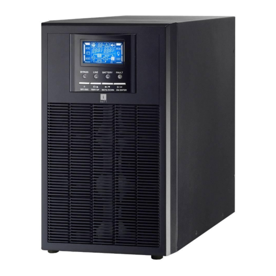
- Page 1 Single Phase Online UPS Liebert GXT MT+LB 10kVA UPS User Manual...
- Page 2 Please comply with all warnings and operating instructions in this manual strictly. Save this manual properly and read carefully the following instructions before installing the unit. Do not operate this unit before reading through all safety information and operating instructions carefully.
-
Page 3: Table Of Contents
Table of Contents 1. SAFETY AND EMC INSTRUCTIONS ....................3 1-1. T ......................3 RANSPORTATION AND TORAGE 1-2. P ..........................3 REPARATION 1-3. I ..........................3 NSTALLATION 1-4. O ............................ 4 PERATION 1-5. S ............................ 4 TANDARDS 2. INSTALLATION AND OPERATION ....................5 2-1. -
Page 4: Safety And Emc Instructions
1. Safety and EMC instructions Please read carefully the following user manual and the safety instructions before installing the unit or using the unit! 1-1. Transportation and Storage Please transport the UPS system only in the original package to protect against shock and impact. The UPS must be stored in the room where it is ventilated and dry. -
Page 5: Operation
1-4. Operation Do not disconnect the earth conductor cable on the UPS or the building wiring terminals in any time since this would cancel the protective earth of the UPS system and of all connected loads. The UPS system features its own, internal current source (batteries). The UPS output sockets or output terminal blocks may be electrically live even if the UPS system is not connected to the building wiring outlet. -
Page 6: Installation And Operation
2. Installation and Operation There are two different types of online UPS: standard and long-run models. Please refer to the following model table. Model Type Model Type Standard Model 10KL Long Model 2-1. Unpacking and Inspection Unpack the package and check the package contents. The shipping package contains: ●... - Page 7 Diagram 2: 6KL/10KL Rear Panel Diagram 3: 6K(L)/10K(L) Input/Output Terminal 1. External battery connector 2. RS-232 communication port 3. Intelligent slot 4. USB communication 5. Emergency power off function connector (EPO connector) 6. Cooling fan 7. Input circuit breaker 8. Input/Output terminal (Refer to Diagram 3 for the details) 9.
-
Page 8: Single Ups Installation
2-3. Single UPS Installation Installation and wiring must be performed in accordance with the local electric laws/regulations and execute the following instructions by professional personnel. Make sure the mains wire and breakers in the building are in compliance with the standard of rated capacity of UPS to avoid the hazards of electric shock or fire. - Page 9 Warning: (Only for standard model) ● Make sure the UPS is not turned on before installation. The UPS should not be turned on during wiring connection. ● Do not try to modify the standard model to the long-run model. Particularly, do not try to connect the standard internal battery to the external battery.
-
Page 10: Installation For Hot Standby
2-4. Installation for hot standby If the hot standby function is not used, you may skip this section. 1) Disconnect the jumper wire between the terminals of “BPS” and “L0” on the host UPS. 2) Keep the jumper wire between the terminals of “BPS” and “L0” on the standby UPS. 3) Connect the “L1”... -
Page 11: Operations
3. Operations 3-1. Button Operation Button Function Turn on the UPS: Press and hold the button more than 0.5s to turn on the UPS. ON/Enter Button Enter Key: Press this button to confirm the selection in setting menu. Turn off the UPS: Press and hold the button more than 0.5s to turn off the UPS. OFF/ESC Button Esc key: Press this button to return to last menu in setting menu. - Page 12 LCD Panel: Display Function Backup time information Indicates the backup time in pie chart. Indicates the backup time in numbers. H: hours, M: minute, S: second Setting operation Indicates the setting operation. Fault & warning information Indicates that the warning situation occurs. Indicates the warning and fault codes, and the codes are listed in details in “Faults Reference Code”...
-
Page 13: Audible Alarm
Indicates the UPS is charging battery. Battery information Indicates the Battery capacity by 0-25%, 26-50%, 51-75%, and 76-100%. Indicates the battery is fault. Indicates low battery level and low battery voltage. 3-3. Audible Alarm Description Buzzer status Muted UPS status Bypass mode Beeping once every 2 minutes Battery mode... - Page 14 running and the UPS supplies power to the loads via the bypass. The UPS is operating in Bypass mode. NOTE: When UPS is in Bypass mode, the output voltage will directly power from utility after you switch on the input breaker. In Bypass mode, the load is not protected by UPS. To protect your precious devices, you should turn on the UPS.
- Page 15 5. Battery mode operation 1) When the UPS is in Battery mode, the buzzer will beep according to different battery capacity. If the battery capacity is more than 25%, the buzzer will beep once every 4 seconds; If the battery voltage drops to the alarm level, the buzzer will beep quickly (once every sec) to remind users that the battery is at low level and the UPS will shut down automatically soon.
- Page 16 10. Operation in warning status 1) When Fault LED flashes and the buzzer beeps once every second, it means that there are some problems for UPS operation. Users can get the fault code from LCD panel. Please check the trouble shooting table in chapter 4 for details.
-
Page 17: Abbreviation Meaning In Lcd Display
3-5. Abbreviation Meaning in LCD Display Abbreviation Display content Meaning Enable Disable Auto Not allowed Allow 3-6. LCD Display 3-6-1. LCD Main Interface A. Single model: Press up and down key to select the displayed information. 1 Output Voltage 2 Output Frequency 3 Battery Voltage 4 Load Level 5 Environmental Temperature... - Page 18 3-6-2. LCD Setting At the main interface; press and hold the “up” and “down” buttons simultaneous for more than 1 second to enter or escape from setting menu. There are two parameters to set up the UPS. Refer to following diagram. Parameter 1: It’s for program alternatives.
- Page 19 01: Output voltage Interface Setting Parameter 2: Output voltage You may choose the following output voltage in parameter 3: 208: Presents output voltage is 208Vac 220: Presents output voltage is 220Vac 230: Presents output voltage is 230Vac 240: Presents output voltage is 240Vac 02: Frequency Converter enable/disable Interface Setting...
- Page 20 Interface Setting Parameter 2: Allow or forbidden bypass mode FBD: Bypass not allowed. When selected, it’s not allowed for running in Bypass mode under any situations. OPN: Bypass allowed. When selected, UPS will run at Bypass mode depending on the setting of “Switch off Bypass mode enable/disable”.
- Page 21 08: Voltage range for bypass Interface Setting Parameter 2: Set the acceptable low voltage for bypass. Setting range is from 110V to 209V and the default value is 176V 09: Voltage range for bypass Interface Setting Parameter 2: Set the acceptable low voltage for bypass. Setting range is from 231V to 276V and the default value is 264V 10: Frequency range for bypass Interface...
- Page 22 Parameter 2: Set Battery voltage calibration. the voltage range is from -5.7V to 5.7V.the default value is 0V. 13: charger voltage calibration Interface Setting Parameter 2: Set charger voltage calibration. the voltage range is from -6.4V to 6.4V, the default value is 0V. 14: Inverter voltage calibration Interface Setting...
- Page 23 15: Charger maximum current setting Interface Setting Parameter 2: The maximum charging current could be adjusted. Default value is 4A for long run model and 1A for standard model. The setting range is 0.5A~6A for long run model, and 0.5A~2A for standard model Note: Any modification should be suitable to battery specifications.
-
Page 24: Operating Mode/Status Description
3-7. Operating Mode/Status Description Operating Description LCD display mode/status AC mode When the input voltage is within acceptable range, UPS will provide pure and stable AC power to output. The UPS will also charge the battery at AC mode. CVCF mode When input frequency is between 46Hz and 64Hz, the UPS can be set at a constant output frequency, 50 Hz or 60 Hz. -
Page 25: Fault Code
3-8. Fault Code Fault event Fault code Icon Fault event Fault code Icon Bus start failure None Battery SCR short circuited None Bus over None Inverter relay short circuited None Bus under None Charger output short None Bus unbalance None Parallel communication None failure... -
Page 26: Trouble Shooting
4. Trouble Shooting If the UPS system does not operate correctly, please solve the problem by referring to the table below: Alarm Code Icon Possible cause Remedy type Warning 1) The battery is not connected 1) Connect the battery well; well;... - Page 27 Alarm Code Possible cause Remedy Icon type The internal converter failed, so the Contact the dealer for repair Fault DC bus voltage could not be boosted correctly. Fault 1) The mains input load 1) Shut down and restart the UPS to transient current cause the DC see if it happens again.
-
Page 28: Storage And Maintenance
5. Storage and Maintenance 5-1. Storage Before storing, charge the UPS at least 7 hours. Store the UPS covered and upright in a cool, dry location. During storage, recharge the battery in accordance with the following table: Storage Temperature Recharge Frequency Charging Duration -25°C - 40°C Every 3 months... -
Page 29: Specifications
6. Specifications MODEL GXT MT+ LB, 10kVA CAPACITY* 10000 VA / 8000 W INPUT 110 VAC ± 3 % at 50% Load; Low Line Loss 176 VAC ± 3 % at 100% Load Voltage Range Low Line Comeback Low Line Loss Voltage + 10V High Line Loss 300 VAC ±...
Need help?
Do you have a question about the Liebert GXT MT+LB 10KL and is the answer not in the manual?
Questions and answers