Table of Contents
Advertisement
Advertisement
Table of Contents

Related Manuals for Estyma iGNEO COMPACT

Summary of Contents for Estyma iGNEO COMPACT
- Page 1 BOILER CONTROLLER COMPACT...
- Page 2 page 2 PL20110629...
-
Page 3: Table Of Contents
4.5 Service password 5 Simple menu 5.1 Simple menu screens 6 Main menu 6.1 Heating 6.1.1 Selection of circuit..................24 6.1.2 State......................24 6.1.3 Settings......................25 6.1.4 Time program....................25 6.1.5 Service......................26 6.2 Hot water estyma electronics page 3 www.estyma.pl PL20110629... - Page 4 Index 6.2.1 Selection of circuit..................28 6.2.2 State......................28 6.2.3 Settings......................29 6.2.4 Time program....................29 6.2.5 Service......................30 6.3 Buffer 6.3.1 State......................31 6.3.2 Settings......................31 6.3.3 Time program....................32 6.3.4 Service......................32 6.4 Boiler 6.4.1 State......................33 6.4.2 Settings......................33 6.4.3 Service......................
-
Page 5: General Information
Team 1.1 Introduction Controller IGNEO Compact is a modern microprocessor system, which controls not only the boiler, but also the central heating system and domestic hot water. The device controls the burning process by providing the appropriate amount of air and fuel. - Page 6 1 General information The modular construction of the CAN - using industrial CAN bus data exchange (mainly used in the demanding automotive industry), it is possible to expansion of the system. The maximum extension is 16 heating circuits, two circuits of hot water, energy buffers and solars. Buffer - controlling the heating system in combination with heat storage reservoir.
-
Page 7: Safety Precautions
When connecting the unit to power supply, make sure that the parameters of the supply network are within the unit’s operating range. • All electrical connections must be as shown in the electrical assembly drawings and must comply with national and/or local regulations concerning electrical connections. estyma electronics page 7 www.estyma.pl PL20110629... -
Page 8: Disposal Of Old Equipment
1 General information • This unit contains no parts that may be replaced by the user. All maintenance work except for cleaning, fuse replacement (when the unit is de-energized), and function setting, should be performed by an authorized service provider. •... -
Page 9: Connecting To The System
3. The temperature in the location must not exceed 60ºC and should not be lower than 0ºC. Humidity should be within the range from 5% to 95%, with no vapour condensation taking place. estyma electronics page 9 www.estyma.pl PL20110629... -
Page 10: Assembly
2 Connecting to the system 2.3 Assembly The controller is designed for mounting in a wall or plate mounting. Plate thickness should not exceed 3mm. The minimum depth of the mounting hole is 100mm. The dimensions of the hole and controller are indicated in the figure below. After placing the panel in the hole, always install the mounting frame. -
Page 11: Connecting
(N). Warning !!! Wiring must be done with the device disconnected from the mains. Connections should be exercised by a person possessing adequate powers in this regard. 2.4.1 Direct connection of devices estyma electronics page 11 www.estyma.pl PL20110629... - Page 12 2 Connecting to the system INPUTS Description Explanation Tboiler Boiler temperature sensor Teg / photo Exhaust gas temperature sensor or photocell Tburner The temperature sensor burner The temperature sensor hot water Troom Room temperature sensor / regulator (CTP) The temperature sensor central heating Tout Outdoor temperature sensor (CTZ) +12V output to supply optional equipment...
-
Page 13: Connecting Using Burner Wire
2 Connecting to the system 2.4.2 Connecting using burner wire estyma electronics page 13 www.estyma.pl PL20110629... - Page 14 2 Connecting to the system INPUTS Description Explanation Tboiler Boiler temperature sensor 5 (Teg) Photocell 6 (Tbur) The temperature sensor burner The temperature sensor hot water Troom Room temperature sensor / regulator (CTP) The temperature sensor central heating Tout Outdoor temperature sensor (CTZ) +12V output to supply optional equipment +5V output to supply optional equipment 7 (GND)
-
Page 15: Overview Of The Basic Functions
Green light continuously Controller OFF Green blinks Controller enabled, burner OFF Orange light continuously Controller enabled, burner enabled Orange blinks Burner works Red light continuously There is an alarm to be confirmed Red blinks Alarm active estyma electronics page 15 www.estyma.pl PL20110629... -
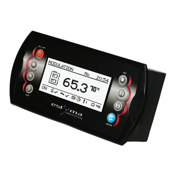
Page 16: Buttons
3 Overview of the basic functions 3.1.2 Buttons Button Function Long press on the main screen (>3 seconds) changes the state of the ON/OFF (on/off). ON / OFF Quick access to the full configuration settings for the central heating. Quick access to the full configuration settings for hot water. Shows the navigation information and descriptions of the regulated parameters. -
Page 17: Graphic Display
Quenching of the furnace. Work of burner and blower tray until the complete disappearance of the flame. STOP Burner does not work but it is to agree to his work. The required boiler temperature is reached. estyma electronics page 17 www.estyma.pl PL20110629... -
Page 18: Handling
4 Handling 4 Handling 4.1 Navigation in the menu The device has two types of menus: simple and main menus. Simple menu - allows for quick access to basic controller functions. Enter the menu is simple by pressing the "up arrow"or "down arrow" on the main screen. Description of a simple menu in chapter 5. -
Page 19: Time Scheduling
WARNING !!! Values of temperatures comfortable and economical are set in the “SETTINGS” menu and may be different for each of the circuits. To make the time program work, you must also enable a timed mode in the “SETTINGS” menu. estyma electronics page 19 www.estyma.pl... -
Page 20: Service Password
4 Handling 4.5 Service password Access to the service parameters are password protected. After entering the correct password, access will be lifted. Access to the service parameters will be locked after a period of 10 minutes without pushing buttons. Service code is a temperature of the boiler in menu BOILER / SETTINGS and 3 letters "EST". -
Page 21: Simple Menu
"ENTER" set the desired temperature of hot water. Menu relates to the circuit No. 1 Disposable heating hot water to a comfortable temperature regardless of the program. Menu relates to the circuit No. 1 estyma electronics page 21 www.estyma.pl PL20110629... - Page 22 5 Simple menu Set the mode a hot water: a) time - according to the programmed timescales b) constatant - regardless of the time intervals comfortable temperature is maintained c) disabled - off the heat Menu relates to the circuit No. 1 Shows the current temperature in the room No 1 (large font) and the value of the desired (small font).
-
Page 23: Main Menu
24 6.2 Hot water page 28 6.3 Buffer page 31 6.4 Boiler page 33 6.5 Settings page 35 6.6 Burner page 38 6.7 Alarms page 40 6.8 Solar page 46 6.9 Info page 47 estyma electronics page 23 www.estyma.pl PL20110629... -
Page 24: Heating
6 Main menu 6.1 Heating 6.1.1 Selection of circuit Allows you to select a number of central heating circuit. The selection of the circuit make arrows. 6.1.2 State Allows you to monitor the status of central heating system. page 24 PL20110629... -
Page 25: Settings
Economical temp. Desired temperature in the room outside the period of heating. 6.1.4 Time program Used to configure the time program steering central heating. Description of the adjustment time program refer to chapter 4.4. estyma electronics page 25 www.estyma.pl PL20110629... -
Page 26: Service
6 Main menu 6.1.5 Service WARNING !!! Access the service is intended only for qualified technical personnel. The changes may cause malfunction of the system. Service Function Description Comf. MAX pump temp. Maximum outdoor temperature at which the circulating pump can work in a comfortable range. - Page 27 (only with the use of a sensor for central heating and room sensor), No - after reaching the set temperature in the room the pump is turned off. estyma electronics page 27 www.estyma.pl PL20110629...
-
Page 28: Hot Water
6 Main menu 6.2 Hot water 6.2.1 Selection of circuit Allows you to select the number of hot water circuit. 6.2.2 State Allows you to monitor the status of hot water. page 28 PL20110629... -
Page 29: Settings
Economical temp. Desired temperature of hot water outside the period of heating. 6.2.4 Time program Used to configure the time steering hot water preparation. Description of the adjustment time refer to chapter 4.4. estyma electronics page 29 www.estyma.pl PL20110629... -
Page 30: Service
6 Main menu 6.2.5 Service WARNING !!! Access the service is intended only for qualified technical personnel. The changes may cause malfunction of the system. Service Function Description Source delta Increasing the temperature of the source of the desired temperature of hot water during heating. -
Page 31: Buffer
Programme Constant - the buffer is charged regardless of the time, time - the buffer charged only at specified intervals. Intervals are set in the "time program", disabled - off charging buffer. estyma electronics page 31 www.estyma.pl PL20110629... -
Page 32: Time Program
6 Main menu 6.3.3 Time program Used to configure time program to controlling charging buffer. Description of program adjustment time refer to chapter 4.4. 6.3.4 Service WARNING !!! Access the service is intended only for qualified technical personnel. The changes may cause malfunction of the system. -
Page 33: Boiler
Across the screen are displayed statistics of 2 hours. Screens switching buttons "up" and "down". 6.4.2 Settings Settings Function Description Boiler temp. set Heating water temperature in the boiler which will be maintain the controller. Menu is active only in continuous work mode. estyma electronics page 33 www.estyma.pl PL20110629... -
Page 34: Service
6 Main menu 6.4.3 Service WARNING !!! Access the service is intended only for qualified technical personnel. The changes may cause malfunction of the system. Service Function Description MIN pump temp. The temperature above which the the controller can attach pumps. Mode Operating mode of boiler: a) auto - temperature calculated automatically... -
Page 35: Settings
We define here, if the driver shall notify of alarms by acoustic signal. 6.5.4 Service WARNING !!! Access the service is intended only for qualified technical personnel. The changes may cause malfunction of the system. estyma electronics page 35 www.estyma.pl PL20110629... - Page 36 6 Main menu 6.5.4.1 Module configuration Menu is used to configure the CAN network. In the menu, select the modules that are connected to the system. WARNING !!! A detailed description of the modules and their destination are described in the manual of expansion modules.
- Page 37 This function allows the controller to restore the factory settings. WARNING !!! Will be restored all factory settings, which can cause your system to malfunction. After restoring the factory settings may be need to reconfigure the controller settings. estyma electronics page 37 www.estyma.pl PL20110629...
-
Page 38: Burner
6 Main menu 6.6 Burner 6.6.1 State 6.6.2 Settings Settings Function Description Feed fuel now Starts fuel feeding screw regardless of other features. Burner on Consent to work of the burner. Fuel type Specifies the type of fuel. page 38 PL20110629... -
Page 39: Service
Oxygen MIN (20%) Oxygen target for minimal power. Oxygen MAX (100%) Oxygen target for maximal power. * testing equipment in the menu “BURNER” is only possible when the controller is in the OFF mode. estyma electronics page 39 www.estyma.pl PL20110629... -
Page 40: Alarms
6 Main menu 6.7 Alarms This menu contains a history of up to 20 alarms that occurred during the controller work. The importance of alarm codes was presented in table below. 6.7.1 Alarm codes ALARM CODES AND THEIR SIGNIFICANCE CODE Short description Explanation Procesor overheating. - Page 41 Lambda communication Solars overheating Solars freezing The codes of the modules Shorted IN1 Module 0 Shorted IN2 Module 0 Shorted IN3 Module 0 Shorted IN4 Module 0 Shorted IN5 Module 0 Shorted IN6 Module 0 estyma electronics page 41 www.estyma.pl PL20110629...
- Page 42 6 Main menu Shorted IN11 Module 0 Open IN1 Module 0 Open IN2 Module 0 Open IN3 Module 0 Open IN4 Module 0 Open IN5 Module 0 Open IN6 Module 0 Open IN11 Module 0 Overheating Module 0 Shorted IN1 Module 1 Shorted IN2 Module 1 Shorted IN3 Module 1 Shorted IN4 Module 1...
- Page 43 Shorted IN4 Module 2 Shorted IN5 Module 2 Shorted IN6 Module 2 Open IN1 Module 2 Open IN2 Module 2 Open IN3 Module 2 Open IN4 Module 2 Open IN5 Module 2 Open IN6 Module 2 estyma electronics page 43 www.estyma.pl PL20110629...
- Page 44 6 Main menu Overheating Module 2 Shorted IN1 Module 3 Shorted IN2 Module 3 Shorted IN3 Module 3 Shorted IN4 Module 3 Shorted IN5 Module 3 Shorted IN6 Module 3 Open IN1 Module 3 Open IN2 Module 3 Open IN3 Module 3 Open IN4 Module 3 Open IN5 Module 3 Open IN6 Module 3...
- Page 45 Shorted IN1 Module 5 Shorted IN2 Module 5 Shorted IN3 Module 5 Shorted IN4 Module 5 Shorted IN6 Module 5 Shorted IN7 Module 5 Shorted IN8 Module 5 Shorted IN9 Module 5 Overheating Module 5 estyma electronics page 45 www.estyma.pl PL20110629...
-
Page 46: Solar
6 Main menu 6.8 Solar 6.8.1 State 6.8.2 Settings Settings Function Description Turn on delta Temp. difference between solar and accumulator needed for solar pump turn on. Turn off delta Temp. difference between solar and accumulator needed for solar pump turn off. page 46 PL20110629... -
Page 47: Service
Minimal temp. of solar collector. Alarm and antifreeze procedure are taken under this temp. Solar pump test Allow for solar pump testing. 6.9 Info There you will find useful information about the controller, including the version of software. estyma electronics page 47 www.estyma.pl PL20110629... -
Page 48: Expansion Of The System - Can Bus
7 Expansion of the system - CAN bus 7 Expansion of the system - CAN bus The controller is equipped with a high bandwidth CAN bus used to communicate with the modules. Thanks to the well-known for their reliability, widely used in automotive bus system is expandable to the highest level. - Page 49 The table describing the functions refer to chapter 6.5.4.2. On the next page is a sample diagram of the system. Please note that this is only overhead view, not containing all the elements of the system. estyma electronics page 49 www.estyma.pl PL20110629...
- Page 50 7 Expansion of the system - CAN bus page 50 PL20110629...
-
Page 51: Sonda Lambda
After connecting the module configure the controller yet. For this purpose, proceed as explained below. From the main menu select SETTINGS Then in the mode SERVICE enter the access code After inputting the correct code, run the MODULES CONFIGURATION estyma electronics page 51 www.estyma.pl PL20110629... - Page 52 7 Expansion of the system - CAN bus Find Lambda Module and turn it on by changing the option to YES At this point, turned on the module Lambda. The second step is a change the configuration settings for the burner. From the main menu by selecting BURNER we get to the settings Here you can again enter the mode SERVICE and if required, enter the access code In the list, you can locate the position Lambda control, which switches on YES.
-
Page 53: Solars
The first step is to enable module number 5. From the main menu select SETTINGS Then in the mode SERVICE enter the access code After inputting the correct code, run the MODULES CONFIGURATION estyma electronics page 53 www.estyma.pl PL20110629... - Page 54 7 Expansion of the system - CAN bus Find Module 5 and activate it by changing the settings to YES Now enable the solar handling. As the main menu select SETTINGS and then enter the access code in the SERVICE mode After entering the code run SYSTEM CONFIGURATION Find the position Solars and activate them by changing the settings to YES After finishing configuration the controller we can start to change the adjustment and settings...
-
Page 55: Specification
NTC 10kΩ B =3877K±0,75% 25/85 VISHAY BC components Ambient temperature 0-60ºC Moisture 5-95% non-condensing Software class Module output load capacity CH pump 100W HW pump 100W Igniter 400W Blower 150W Burner feeder 150W Feeder tank 150W estyma electronics page 55 www.estyma.pl PL20110629... - Page 56 Manufactured by: Estyma electronics tel. +48 87 429 86 75 al. Lipowa 4 fax +48 87 429 86 75 11-500 Giżycko biuro@estyma.pl POLAND www.estyma.pl page 56 PL20110629...
Need help?
Do you have a question about the iGNEO COMPACT and is the answer not in the manual?
Questions and answers