Table of Contents
Advertisement
Quick Links
Advertisement
Table of Contents

Related Manuals for Solid State Logic XLogic Alpha-Link LIVE-R


Summary of Contents for Solid State Logic XLogic Alpha-Link LIVE-R
- Page 1 XLogic Alpha-Link LIVE-R User Guide XLogic Alpha-Link. This is SSL.
- Page 2 Document History 82BSBM01A (July 2011) Initial release (October 2011) Minor typos corrected, clarified saving settings...
-
Page 3: Table Of Contents
Contents Introduction Virtual Switches, Page One Notes for Virtual Switches, Page One Scope Virtual Switches, Page Two I/O Capabilities Notes for Virtual Switches, Page Two Installation Notes Virtual Switches, Page Three Front Panel Notes for Virtual Switches, Page Three Power Switch Virtual Switches, Page Four Status LED Appendix A –... -
Page 5: Introduction
Introduction Congratulations on your purchase of this Solid State Logic Alpha-Link LIVE-R audio I/O unit. Please be assured that it will provide you with many years of reliable service while delivering the pristine audio quality you expect from any Solid State Logic product. -
Page 6: Scope
Registration will also make you eligible for technical support. The Solid State Logic home page is at: www.solidstatelogic.com From there you can access our Support page, which includes links to the Product Registration and Download pages. -
Page 7: I/O Capabilities
I/O Capabilities The number of channels available on each audio interface provided by the Alpha-Link LIVE-R is determined by the sample rate and in certain circumstances by the mode of operation chosen. The LIVE-R can operate at the following sample rates; 44.1kHz, 48kHz, 88.2kHz, 96kHz, 176.4kHz and 192kHz and if locked to an external clock source, it can also operate at a deviation of up to 10% from these rates. -
Page 8: Installation Notes
Installation Notes Please take time to read through this guide before installing your Alpha-Link LIVE-R. If however you are unable to resist that temptation, do take note of the following points: • Full connector pin-out details are provided at the rear of the Alpha-Link LIVE-R Installation Guide. •... -
Page 9: Front Panel
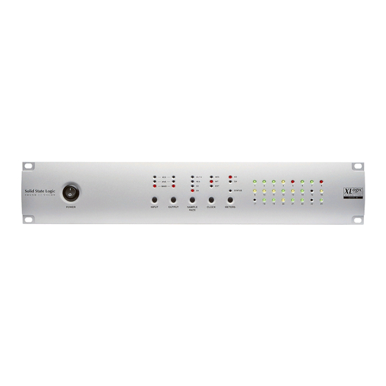
Front Panel Routing Matrix Clock Source Power Switch Control Selection Signal Meters Sample Rate Status LED Selection Power Switch This is used to switch the Alpha-Link LIVE-R on or off. All front panel settings are stored in non-volatile memory ~5 sec after the last front panel change; please allow time for this before switching the unit off. -
Page 10: Routing Matrix Control
Routing Matrix Control The Alpha-Link LIVE-R contains a routing matrix which enables routing AES/EBU of groups of signals between the inputs and outputs. This routing matrix is controlled using two buttons – one to select an OUTPUT Analogue and the other to pick the INPUT for that output – along with a set of MADI indicator LEDs to show the routing setup. -
Page 11: Viewing And Setting Routing
Viewing and Setting Routing Pressing the OUTPUT button repeatedly will cycle through the available output groups, the currently selected output group being indicated by the corresponding LED. For each output group, the LEDs of the input column will indicate which input group(s) are connected to that output group. To set or change the input group(s) connected to a given output group: •... -
Page 12: Clock Source Selection
Clock Source Selection The Alpha-Link LIVE-R unit can operate either as a Clock Master device AES/EBU (‘Internal’ mode), or as a Clock Slave device locked to an external clock signal. Possible external sources are: Internal External • AES/EBU (MADI, Video or Wordclock) •... -
Page 13: Sample Rate Selection
Sample Rate Selection The sample rate indicators show the current sample rate of the unit. When 44.1kHz the Alpha-Link LIVE-R clock source is set to ‘Internal’ (see opposite), pressing the SAMPLE RATE button will step through each available sample rate 48kHz (44.1kHz, 48kHz, 88.2kHz, 96kHz, 176.4kHz and 192kHz) –... -
Page 14: Signal Meters
Signal Meters The meter section of the front panel provides simple tri-colour LED metering for either the 24 analogue inputs (AD) or the 24 analogue outputs (DA), selectable using the METERS button. Input Metering Output Metering Tri-colour LED Meters (24 Channels) For each input or output channel, the signal level is represented by the state of the LED with the corresponding number. -
Page 15: System Settings And Diagnostics
System Settings and Diagnostics Each Alpha-Link LIVE-R unit is configured by Current option settings for the default to work in a simple system. Many users selected page however may find that these defaults are not appropriate for their setup. To cater for such situations the default settings may be adjusted STATUS using a set of virtual switches, accessed from... -
Page 16: Selecting An Option
Selecting an Option For each page of switches, the middle row of meter LEDs indicates, in RED, the currently selected switch such that Channel 9 LED indicates Switch 1, Channel 10 indicates Switch 2 etc. Pressing the OUTPUT button will cycle through all switches for that page. -
Page 17: Firmware Version
The Alpha-Link LIVE-R firmware can be updated in the field using the standard USB 2.0 port located on the rear panel. An update utility (MS Windows™ only) can be downloaded from the Support section of the Solid State Logic website to facilitate this. -
Page 19: Virtual Switches, Page One
Virtual Switches, Page One (indicated by an illuminated channel 17 LED) Settings in bold indicate defaults. Please also refer to the notes overleaf for details of each setting. Option Setting LED State See Note 64 (32/16 at 2Fs/4Fs) Number of MADI channels 56 (28/14 at 2Fs/4Fs) High Speed MADI 2Fs/4Fs data format... -
Page 20: Notes For Virtual Switches, Page One
Notes for Virtual Switches, Page One 1. There are two MADI channel formats; 56 or 64 channel. The 56 channel format allows for 10% deviation from the nominal sample rate whilst the 64 channel format uses the full capacity of the MADI stream fixed to the selected sample rate. - Page 21 b. If the unit is not set to lock to the interface in question and the interface provides multiple data formats , these options are used to set the 2Fs/4Fs data format for that interface: • When set to ‘Legacy (SMUX2 or SMUX4) a half-rate frame pattern will be used. This format is functionally compatible with Fs rate interfaces and may be required to interface to older equipment.
-
Page 22: Virtual Switches, Page Two
Virtual Switches, Page Two (indicated by an illuminated channel 18 LED) Settings in bold indicate defaults. Please also refer to the notes opposite for details regarding each setting. Option Setting LED States See Note AES/EBU In 1 & 2 AES/EBU In 3 & 4 AES/EBU clock source (port ‘A’... -
Page 23: Notes For Virtual Switches, Page Two
Notes for Virtual Switches, Page Two 1. The Alpha-Link LIVE-R unit can optionally lock to one of the four AES/EBU inputs provided on AES/EBU port ‘A’. To enable one of these four inputs to be selected the first two option switches operate together. The current AES clock input selection is shown by the status of the channel 1 and channel 2 metering LEDs. -
Page 24: Virtual Switches, Page Three
Virtual Switches, Page Three (indicated by an illuminated channel 19 LED) Settings in bold indicate defaults. Please also refer to the notes opposite for details regarding each setting. Option Setting LED States See Note Unused – None External Wordclock Currently Unused AES A 1/2 Fallback Clock Source AES A 3/4... -
Page 25: Notes For Virtual Switches, Page Three
Notes for Virtual Switches, Page Three 1. This option sets an alternative clock source to automatically take over if the main External Clock Source fails (see notes 2. though 4. below). Note that video sync is not available as a Fallback Clock Source. 2. -
Page 26: Virtual Switches, Page Four
Virtual Switches, Page Four (indicated by an illuminated channel 20 LED) Settings in bold indicate defaults. Please also refer to the notes below for details regarding each setting. Option Setting LED States See Note +14dBu +15dBu +16dBu +18dBu Analogue Operating Level +20dBu +21dBu +22dBu... -
Page 27: Appendix A - Aes/Ebu Interface
Appendix A – AES/EBU Interface Inputs with Sample Rate Conversion The inputs of AES/EBU port A (channels 1 through 8) have sample rate conversion available. These sample rate converters combine a wide input-to-output sampling ratio with outstanding dynamic range and ultra low distortion, resulting in high quality even at a 1:1 conversion (where many SRCs offer their lowest quality). -
Page 28: Appendix B - Troubleshooting
Appendix B – Troubleshooting Symptom Possible Solution Check that the Alpha-Link LIVE-R unit is connected to the There is no sound, all the LEDs are off. mains supply and that the Power switch is in the ‘ON’ position. Check the condition of the mains cable. There is no sound. -
Page 29: Support Faqs
Support FAQs Support information for the entire SSL Alpha-Link range of audio I/O is always available through our online support site: www.solidstatelogic.com/support If you can’t find the answer or solution for your particular issue, questions and queries can be submited to our support staff. -
Page 31: Appendix C - Alpha-Link Model Numbers
Appendix C – Alpha-Link Model Numbers The SSL Alpha-Link range provides a variety units for different applications. The following table correlates the major differences between the different models, including the Alpha-Link LIVE-R, with the unit part numbers to aid identification of units: SSL Part Number 1 Unit Identifier 2 Analogue I/O Level 3... - Page 32 As research and development is a continual process, Solid State Logic reserves the right to change the features and specifications described herein without notice or obligation. Solid State Logic cannot be held responsible for any loss or damage arising directly or indirectly from any error or omission in this manual.
Need help?
Do you have a question about the XLogic Alpha-Link LIVE-R and is the answer not in the manual?
Questions and answers