Table of Contents
Advertisement
Quick Links
Advertisement
Table of Contents

Subscribe to Our Youtube Channel
Related Manuals for Solid State Logic THE BUS+


Summary of Contents for Solid State Logic THE BUS+
- Page 1 www.solidstatelogic.com THE BUS User Guide THE BUS+...
- Page 2 As research and development is a continual process, Solid State Logic reserves the right to change the features and specifications described herein without notice or obligation. Solid State Logic cannot be held responsible for any loss or damage arising directly or indirectly from any error or omission in this manual.
-
Page 3: Table Of Contents
Contents Table of Contents Overview The Bus Compressor Legacy Creating The Ultimate Features Unpacking Rack Mounting, Heat and Ventilation Safety Notices Hardware Overview Front Panel Rear Panel Tutorial MODE Selection CH 1 IN and CH 2 IN Switches Overload (Clipping) Indication Mid Solo and Side Solo Sleep Mode Gain Reduction Meters... -
Page 4: Overview
Introduction Overview The Bus Compressor Legacy If there is a single piece of analogue processing equipment that is synonymous with SSL, it just has to be The SSL Bus Compressor. From the very first commercially released SSL 4000 B console in 1976 and through many generations of SSL consoles that have followed since, the Bus Compressor has always been the stalwart of the console centre section. -
Page 5: Features
Introduction Features The Bus+ (General) The Bus+ combines a feature-rich analogue SSL Bus Compressor with a powerful Dynamic EQ, all in a single 2U rack unit ➤ 100% analogue circuit, controlled digitally using the stepped front-panel pots ➤ 4 modes of operation - Classic Stereo, � S/C Stereo, Dual Mono or Mid-Side ➤... -
Page 6: Unpacking
Introduction Unpacking The unit has been carefully packed and inside the box you will find the following items. ➤ The Bus+ ➤ IEC power cord for your country ➤ Safety Sheet ➤ Quickstart Guide It is always a good idea to save the original box and packaging, just in case you ever need to send the unit in for service. Rack Mounting, Heat and Ventilation The Bus+ is a 2U, 19”... -
Page 7: Hardware Overview
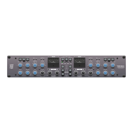
Hardware Overview Hardware Overview This page provides a brief overview of The Bus+ hardware. The tutorial section covers each control in more detail. Front Panel BUS COMPRESSOR SWITCHES MODE MOVING-COIL METER Special Bus Compressor features, Determines the mode of operation. Displays Gain Reduction for the Bus unique to The Bus+ : LOW THD, F/B, Choose from Classic Stereo, �... -
Page 8: Tutorial
Tutorial Tutorial MODE Selection The Bus+ has four different modes of operation to choose from. Pressing the MODE switch will move you through the options. CLASSIC STEREO - This is the classic mode of operation for the SSL Bus Compressor. Designed to be used on stereo sources, the controls on the left-hand side of the unit determine the settings of both left and right channels. -
Page 9: Overload (Clipping) Indication
Tutorial Overload (Clipping) Indication The CH 1 IN and CH 2 IN switches will indicate if the headroom of the unit has been exceeded by flashing red when the signal passing through the unit registers above 26.5 dBu (i.e. 1 dB below absolute headroom of +27.5 dBu). -
Page 10: Bus Compressor Controls
Tutorial Bus Compressor Controls THRESHOLD - Determines the level at which compression occurs. 31-position stepped pot ranging from -20 to +20 dB. ATTACK - Sets the attack time of the compressor (in milliseconds). 11-position stepped pot ranging from .1 to 40 ms. The Bus+ features a number of Attack time options never before seen on an SSL Bus Compressor, including 6, 15, 20 and 40 ms. - Page 11 Tutorial S/C HPF (SIDE-CHAIN HIGH-PASS FILTER) Introduces a 12 dB/oct (2nd order) High-Pass Filter into the compressor side-chain. 31-position stepped pot ranging from OUT (fully counter-clockwise) to 300 Hz (fully clockwise). Steps are in 10 Hz resolution. Allows the dry (uncompressed) and wet (compressed) signal paths to be blended together. 31-position stepped pot range from DRY (fully counter-clockwise) to WET (fully clockwise).
- Page 12 Tutorial F/B (FEED-BACK) MODE Although the Bus Compressor side-chain per se has a 'feed-back' topology, the signal feeding the side-chain is derived from a feed-forward position. Engaging the F/B switch derives the signal feeding the side-chain from a feed-back position (i.e. after the main gain-reduction VCA in the audio path).
- Page 13 Tutorial Selecting The External Side-chain Input Pressing the S/C HPF control allows the external side-chain input(s) to be sourced for the Bus Compressor, D-EQ or both. Ext S/C Input - Bus Comp Ext S/C Input - D-EQ Ext S/C Input - Both Ext S/C Input - Off Press once to select Press twice to select the...
-
Page 14: Dynamic Equaliser (D-Eq)
Tutorial Dynamic Equaliser (D-EQ) Many engineers use regular ('static') EQ in addition to their master bus compression, often feeling that they need to compensate for the psychoacoustic perception of 'dulling' that compression can bring. Also, in general, many engineers apply a static EQ across their mix as part of their mixing template to help achieve the level of bass and presence that modern productions require. - Page 15 Tutorial D-EQ Switches By default, the LF and HF bands are first order (6 dB per/oct) shelving filters with nominal attack and release times set in the D-EQ side-chain. However, the following switches allow for some different options: HF BELL Changes the filter type from shelf to bell for the HF band.
- Page 16 Tutorial G (G-Series) Mode Pushing the LF GAIN control will toggle G (G-Series) mode on/off for the LF band. When active, the LED lights GREEN. When the EQ is in G-Series mode, the filters are changed from 1st order to 2nd order (12 dB per octave) and an amount of overshoot/undershoot is added to the shelving filters above the frequency cut-off point, similar to that found on G-Series SSL EQs.
- Page 17 Tutorial D-EQ - Frequency & Range Selection For each band of the D-EQ, 16 different frequency points can be chosen from, allowing control over which part of the frequency spectrum you want to affect. The D-EQ also allows control over a parameter called RANGE for each band. The RANGE parameter allows you to restrict the maximum amount of expansion or compression possible, by introducing gain-reduction (or expansion) limiting on the control voltage for the VCA in the D-EQ.
- Page 18 Tutorial Frequency Points The illustrations below show you the frequency to which each needle position corresponds to. The default frequency of the LF Shelf is 60 Hz. The default frequency of the HF Shelf is 6 kHz. The default frequency of the HF Bell is 4 kHz. BELL The HF BELL filter is a Proportional Q design, reaching a Q value of 1.87 at maximum boost/cut (10dB).
- Page 19 Tutorial Range Points When setting the Range parameter of the D-EQ band, the right-hand side meter displays the current setting. There are 23 different ranges values that can be chosen from. The minimum is a range of 0.5 dB and the maximum if 15 dB. Between 0.5 and 8 dB the steps are in 0.5 dB and between 8 and 15 dB the steps are in 1 dB.
-
Page 20: Settings
Settings Mode & Factory Reset Settings There are a number of configurable settings available for The Bus+. To access these, hold down the MODE key whilst The Bus+ is powering on. Read through the information on the following pages to understand which switches affect which particular setting. -
Page 21: Operating Level - Input Gain Trim
Settings Mode & Factory Reset Operating Level - Input Gain Trim The 4K MODE switch on the right-hand side determines if an Input Trim is applied. Press the switch to cycle through the options. 4K MODE = WHITE: 0 dB (default) This is the standard operating level, generally suitable for most mixing scenarios. -
Page 22: Deep Sleep & Waking Up
Settings Mode & Factory Reset Deep Sleep & Waking Up If the unit is in Auto Sleep mode, it's possible to make it wake up automatically simply by sending audio above 0 dBu. Alternatively, simply press the MODE switch. The Auto wake up function requires part of the audio circuitry to be still powered. After 1 hour of inactivity while in Auto Sleep, the unit enters "deep sleep"... -
Page 23: Side Solo Mode
Settings Mode & Factory Reset Side Solo Mode In normal operation, the Side signal when solo'd is presented on both left and right outputs, in phase. This can be changed to be presented after passing through the M/S decoder, which gives in-phase Side signal on the Left output and out-of-phase Side signal on the Right output. -
Page 24: Factory Reset
Settings Mode & Factory Reset Factory Reset To return the unit to the factory-shipped state, you can perform a factory reset by following these instructions: • Press and hold both channels' (left and right) LOW THD switches during the power-up sequence. •... -
Page 25: Code-Break Master Game
Code-Break Master Game Code-Break Master Game Can you break the code to unlock the Transient Expander? Introduction In true SSL tradition, the engineering team are pleased to bring you the Code-Break Master game built into The Bus+. Aim Of The Game The Bus+ randomly picks a sequence of 4-colours (from a palette of 6). - Page 26 Code-Break Master Game How It Works STEP 1 - Pick your colours At the start of each game, The Bus+ randomly picks (but does not show!) a sequence of colours for the CH 1 IN, HF BELL, HF FAST and LF FAST switches. Each of these switches could be one of a six possible colours - Orange, Red, Green, Blue, Magenta and White.
-
Page 27: The Prize - Unlocked Transient Expander Feature
Code-Break Master Game Top Tip - Using the LOW THD and F/B Switches to Review Previous Guess Rounds After the first round of guessing is complete the LOW THD switch becomes available, allowing you to go back through previous guess rounds, to help make more informed decisions as the game progresses. After the second round of guessing is complete, the F/B switch becomes available, which means you can then move backwards (using the LOW THD) and forwards (using the F/B switch) to review the choices you have made in every round as the game progresses. -
Page 28: Bus Compressor Meter Calibration
Troubleshooting & FAQs Bus Compressor Meter Calibration The Bus+ can be put into Meter Calibration Mode. This mode allows the meter needles to be calibrated for optimal alignment against the 4, 8, 12, 16 and 20 marks, when being used to display the Frequency and Range settings of the D-EQ. - Page 29 Troubleshooting & FAQs Calibration Marks '8', '12', '16', '20' When you are happy with the '4' mark calibration, repeat the same process to line up marks '8', '12', '16' and '20' as closely as you can using the LF FAST and HF FAST switches. Use the left-hand side LOW THD and F/B switches to go to the previous or next line-up positions, should you want to make any changes.
-
Page 30: Troubleshooting
Troubleshooting & FAQs Troubleshooting UID Display UID Display Mode displays the UID number of the firmware currently in use and the hardware revision of both main card and front panel card. To enter UID Display Mode, press and hold the left-hand side F/B switch during the power-up sequence. - Page 31 Troubleshooting & FAQs Soak and Potentiometer Test Mode Soak mode is used to check the correct operation of all lights and indicators on front panel. It cycles through the phases listed below. To enter Soak mode, hold down the left-hand side 4K MODE switch whilst The Bus+ is powering on.
-
Page 32: Specifications
Appendices Specifications General and Bus Compressor Default test conditions (unless otherwise stated): Source impedance of test set: 40 Ω Input impedance of test set: 100 kΩ Reference frequency: 1 kHz Reference level: 0 dBu All unweighted measurements are specified as 20 Hz to 20 kHz bandwidth limited, expressed in dBu Onset of clipping (for headroom measurements) should be taken as 1% THD Measurements taken with default input trim setting (0 dB) All levels are intended balanced... -
Page 33: D-Eq
Appendices D-EQ Default test conditions (unless otherwise stated): Source impedance of test set: 40 ohm Input impedance of test set: 100 kOhm Reference frequency: 1 kHz Reference level: 0 dBu All unweighted measurements are specified as 20 Hz to 20 kHz bandwidth limited, expressed in dBu Onset of clipping (for headroom measurements) should be taken as 1% THD Measurements taken with default input trim setting (0 dB) All levels are intended balanced... -
Page 34: Unit General
Appendices Unit General Power Power Supply Auto-Ranging 100-240 VAC Operating Power 38 Watts Sleep Power < 1 Watt Auto-Sleep Power 10 Watts Physical Width 480 mm / 19 inches Height 88.9 mm / 3.5 inches (2 RU) Depth 303 mm / 11.9 inches (chassis only) 328 mm / 12.9 inches (total including front panel controls) Weight 5.92 kg / 13.1 lbs... -
Page 35: Block Diagram
Appendices Block Diagram THE BUS+ User Guide... -
Page 36: The Bus+ Recall Sheet
Appendices The Bus+ Recall Sheet Track _____________________________________________________________ Artist _____________________________________________________________ Producer _____________________________________________________________ Notes _________________________________________ _____________________________________________________________ _________________________________________ _____________________________________________________________ _____________________________________________________________ _____________________________________________________________ _____________________________________________________________ THE BUS+ User Guide... -
Page 37: Code-Break Master Game - Cheat Code
Appendices Code-Break Master Game - Cheat Code Unlock the Transient Expander (Cheat) Desperate to try the Transient Expander but don't have the patience to win a game of Code-Break Master? Read on to discover how to unlock the Transient Expander without having to win the Code-Break Master game... Power on the unit whilst holding the MODE key down to enter SETTINGS mode. -
Page 38: Safety Notices
Appendices Safety Notices General Safety • Please read and keep this document. • Adhere to all warnings and follow instructions. • This electrical equipment should not be used near water, rain or moisture. • Clean only with dry cloth or products compatible with electrical devices and never when the unit is powered. •... - Page 39 Low Voltage directive (LVD) 2014/35/EU. RoHS notice Solid State Logic has conformed and this product has conformed to European Union’s Directive 2011/65/EU on Restrictions of Hazardous Substances (RoHS) as well as the following sections of California law which refer to RoHS, namely sections 25214.10, 25214.10.2, and 58012, Health and Safety Code;...
- Page 40 Appendices Industry Canada Compliance • This Class A digital apparatus complies with Canadian ICES-003. • Cet appareil numérique de la classe A est conforme à la norme NMB-003 du Canada. Electromagnetic Compatibility EN 55032:2015+A11:2020, Class A. EN 55103-2:2009, Environments E1 - E4. FCC 47CFR Part 15, Sub Part B.
- Page 41 www.solidstatelogic.com THE BUS+...
Need help?
Do you have a question about the THE BUS+ and is the answer not in the manual?
Questions and answers