Table of Contents
Advertisement
Advertisement
Table of Contents

Related Manuals for Solid State Logic ORIGIN


Summary of Contents for Solid State Logic ORIGIN
- Page 1 ORIGIN User Guide...
- Page 2 As research and development is a continual process, Solid State Logic reserves the right to change the features and specifications described herein without notice or obligation. Solid State Logic cannot be held responsible for any loss or damage arising directly or indirectly from any error or omission in this manual.
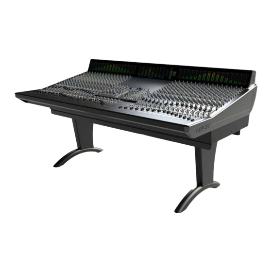
- Page 3 About ORIGIN ORIGIN takes a fresh look at what a large format console needs to do to work in harmony with a modern DAW-driven production studio. The functional design looks back at the ‘ORIGIN’ of in-line consoles for signal flow inspiration, but its circuits are at the cutting edge of SSL’s latest analogue developments.
-
Page 4: Table Of Contents
Contents Table of Contents Introduction Unpacking and Installation Safety Notices Dimensions ORIGIN Channel Strip Channel Strip Overview Detailed Channel Description SuperAnalogue PureDrive™ CHAN (Channel) Pre-Amp input MON (Monitor) Input Input Metering Channel DIRECT OUT Stereo Cue Sends Mono Auxilliary (Aux) Sends... - Page 5 TO MIX and TO BUSES The MISC Section SHIFT/ CLEAR ROUTE Power Management Tools Appendix A - ORIGIN Advanced Routing Routing Terms 'From Channel' Routing - The typical approach for Analogue Consoles Simple Channel to Bus Routing Routing to Multiple Buses...
- Page 6 Channel Equaliser Overall Channel Signal Chain Specifications Crosstalk Overall Console Noise Environmental Requirements Appendix D - ORIGIN Block Diagram Appendix E - Recall Sheets Channel Recall Sheet Master Section Recall Sheet Stereo Group Recall Sheet Appendix F - Suggested Patchbay Layout...
-
Page 7: Introduction
Welcome to ORIGIN... ORIGIN is a console that has traditional analogue ‘in-line’ studio workflow at its heart and is the latest in a long heritage of large format SSL studio mixing consoles. With the evolution of more sophisticated digital audio workstations and new hybrid approaches to session workflow, ORIGIN takes a fresh look at what an analogue console provides to complement these sophisticated tools to make the production process fast, fun and creative. -
Page 8: Unpacking And Installation
This manual assumes that the ORIGIN console has been unpacked, assembled, wired to peripherals such as loudspeakers and connected to a power source. Installation information can be found in the SSL ORIGIN Installation manual, which can be found in the ORIGIN Documents section of the SSL Website (https://www.solidstatelogic.com/) Safety Notices IMPORTANT: Please read the safety notice information included in the Safety Guide supplied inside the box before using ORIGIN. -
Page 9: Origin Channel Strip
70 dB of Gain, 48 V and Polarity Invert. Drive provides a way to change the ultra clean linear pre- An overview of the ORIGIN Channel Strip features. amp to one with gentle warmth from harmonic distortion Section descriptions are in the following pages. -
Page 10: Detailed Channel Description
SuperAnalogue PureDrive™ CHAN (Channel) Pre-Amp input ORIGIN’s pre-amp is a new wide gain range, ultra low noise SuperAnalogue design that provides both Line and Mic level amplification by using a LINE gain range and input source switch to cover a wide range of source signals and levels. -
Page 11: Mon (Monitor) Input
Channel Input Block Diagram METER TRIM MONITOR INPUT PATH FLIP ± 20dB MONITOR Large Fader Path CHAN CHANNEL METER INPUT GAIN DRIVE LINE ø +48V Small Fader Path 1.5K +2 to +70dB [-12 to +55dB] LINE -10dB ORIGIN User Guide... -
Page 12: Input Metering
Each channel SOLO MUTE ORIGIN has a fully balanced DIRECT OUTput. This 'per channel' output provides a way to send the to +10dB selected path signal directly out of the channel strip. This is normally post fader, but selectably pre-fader using the PRE switch. -
Page 13: Stereo Cue Sends
Pre Fader (post Insert) by engaging the corresponding PRE switch. Each send can also be switched to source their feed from the Small Fader path using the SF switch. The channel signal is unity gain to the Cue Bus when the Send Level control is fully clockwise. ORIGIN User Guide... -
Page 14: Parametric Eq And High Pass Filter (Hpf)
Parametric EQ and High Pass Filter (HPF) At the top of the ORIGIN EQ section is the High Pass Filter (HPF) section. This has a 18 dB/ Octave slope and has a variable corner frequency from 10 Hz to 400 Hz. As can be seen in the... -
Page 15: Origin
Detailed Channel Description ORIGIN Path Block Diagram ORIGIN User Guide... -
Page 16: Origin Eq Curves
Detailed Channel Description HF Shelf HF Bell HMF (Min and Max Q) ORIGIN EQ Curves LMF (Min and Max Q) LF Shelf LF Bell ORIGIN User Guide... -
Page 17: Origin
Detailed Channel Description ORIGIN Path Block Diagram ORIGIN User Guide... -
Page 18: Buses (Lf Or Sf Path Routing To Track Buses)
Typically on older analogue consoles, the track routing switches were located at the top of the channel strip. In ORIGIN we have used some clever routing switching to minimise the amount of channel depth used for the routing feature while at the same time adding a powerful and elegant way to route paths to buses. - Page 19 The second way to route signals to Buses from Paths is to start with the Bus selection in the BUS TRIM MASTERS AND ROUTING section in the Centre Section of ORIGIN. Press the bus switch (adjacent to the Bus Trim control) in the BUS TRIM MASTERS AND ROUTING section (e.g.
-
Page 20: Small Fader (Sf) Section
Small Fader Insert ORIGIN has a separate fully balanced Insert for both the Large Fader and Small Fader paths. The primary use of the insert is to bring external processing into the signal path. For example, to insert a dynamics unit such as those found in SSL’s 500 series modules. -
Page 21: Large Fader (Lf) Section
Large Fader (LF) The Large Fader controls the signal level in the LF path. ORIGIN's Large Fader is a 100mm high quality audio fader, with a fader law designed to provide more resolution around the 0 dB point, allowing subtle level changes from modest fader movements. The fader output is unity gain to the bus when the Pan control is hard left or right. - Page 22 Detailed Channel Description Path Block Diagram ORIGIN User Guide...
- Page 23 Detailed Channel Description Channel Section Notes ORIGIN User Guide...
-
Page 24: Stereo Groups
Stereo Groups Origin has eight Stereo Groups in the centre of the console. These are stereo 'audio' groups, i.e. they have audio passing through their faders, as opposed to being VCA control groups. The inputs to these groups are via two DB-25 connectors on the rear of the console labelled ST GRP IP 1-8 and ST GRP IP 9-16. -
Page 25: Buses/Stereo Group Meters
Origin Stereo Groups BUSES/STEREO GROUP METERS Above the Centre Section are the eight stereo meters that show the levels coming into the Stereo Groups. As can be seen in the block diagram on the previous page, the meters are fed after the input buffers and Mono switching, but before the Fader and Balance controls. -
Page 26: Origin Master Section
Origin Master Section ORIGIN Master Section Overview ORIGIN User Guide... -
Page 27: Origin Master Section Detail
Origin Master Section ORIGIN Master Section Detail Stereo Returns ORIGIN has four Stereo Returns for external stereo sources such as external effects or additional stereo submixes. ROUTE The Stereo Groups are able to be routed to the Track Buses in pairs and the routing works in an identical way to the Channel routing (for more details see page 12 or Appendix A). -
Page 28: Bus Masters Trim And Routing
Bus. If the LED is not illuminated then there are no signals routed. If the LEDs are flashing, this indicates the section is in 'Assign' mode and therefore using the Route switches will enable or disable signals. A more thorough explanation of ORIGIN's powerful routing options can be found in the ROUTING section in Appendix A. - Page 29 Origin Master Section LED. The headphone selection can be set up to intercancel with the other monitor selection switches (see Appendix B - Setup Functions), however the level control is independent of the large MONITOR LEVEL control in the MONITOR LEVELS section, but the output does follow the monitor CUT switch.
-
Page 30: Mix Bus Fader
Master Section OSCILLATOR controls. MIX BUS Insert ORIGIN's Mix Bus has a dedicated, fully balanced Insert Send and Return. The Insert Send is always active, with the Insert Return being switched into the Mix Bus circuit using the INSERT switch located next to the Mix Bus fader (see picture left). -
Page 31: Mix Bus Meter
INSERT Origin Master Section As an enhancement to the earlier design, the ORIGIN Mix Bus Compressor has a 2nd order SIDECHAIN HPF (High Pass Filter) with 5 selectable filter frequencies (30, 60, 120, 185 and 300 Hz). Using this control to remove bass frequencies from the sidechain reduces pumping effects when bass heavy mix bus signals 'dominate' the action of the compressor. -
Page 32: Communications
Origin Master Section COMMUNICATIONS As the name implies, the COMMUNICATIONS section is the hub of how the control room communicates with the artists and studio floor. The section is laid out with three columns which represent the three main destinations for the studio, namely FOLDBACK A, FOLDBACK B and STUDIO. - Page 33 Origin Master Section TALK ALL TALK ALL is a grouped 'TALK' function. Typically this simultaneously activates the TALK function for all three communications destinations. This is a momentary switch with an automatic latch feature (see previous paragraph). If it is pressed briefly it will 'latch' on until pressed again.
-
Page 34: Talkback And Listen Mic
Communications (Foldback and Studio) S TUDIO F/B 1 F/B 2 Origin Master Section LEVEL TALK F/BACK AL OUT EXT 1L EXT 1R F/BACK AR OUT to +10dB EXT 4L EXT 1L EXT 4R EXT 1R LEVEL EXT OSC TALK F/BACK BL OUT... -
Page 35: Listen Microphone Connections (Mic And Line Inputs)
Origin Master Section Listen Microphone Connections (Mic and Line Inputs) The Listen Mic Amplifier connection is on the "EXTERNAL INPUTS" DB-25 rear connector. If this DB-25 input is connected via a patchbay, it allows the Listen Mic Amp to be over patched. -
Page 36: Afl, Pfl And The Solo Master Section
AFL, PFL and the SOLO MASTER Section ORIGIN has a comprehensive and flexible After Fade Listen, Pre Fade Listen (AFL/PFL) and Solo In Place (SIP) system. With no options selected, the SOLO switches in the console channel strips activate the AFL function, i.e. they send the selected path to the stereo AFL bus and the monitoring switches to output the AFL bus. -
Page 37: Red Light
External Source selectors. PEAK MODE SELECT The meters in ORIGIN are fast detecting 'peak' meters. These meters have some options for displaying peaks and the PEAK MODE SELECT switch cycles around these modes with repeated pressing. The options are: No Peak Hold. -
Page 38: Dim Chan Meters And Dim Bus Meters
When this switch is pressed with the MISC section SHIFT switch, the MIX meter changes brightness. OSCILLATOR ORIGIN has a simple, yet flexible OSCILLATOR section. It is designed to take advantage of the power of modern hand held devices and the software applications available for them. -
Page 39: Power Management Tools
For these reasons, many older studio consoles are left on 24 hours a day with the associated cooling/air conditioning plant also running at the same time. ORIGIN's circuitry and power supplies are designed to be powered on and off under the control of the console's Power Management Tools. -
Page 40: Appendix A - Origin Advanced Routing
Typically on older analogue consoles, the track routing switches were located at the top of the channel strip, in ORIGIN we have used some clever routing switching to minimise the amount of channel depth (and back stretching!) used for the routing feature while at the same time adding a powerful and elegent way to route paths to buses. -
Page 41: Range Routing - More Channels To More Buses With Less Switch Presses
'To Bus' Routing - The other (more logical!) approach to routing Having central, per Track Bus, routing select switches allows ORIGIN to provide a second way to route to Track Buses. This starts from the bus, not from the Channel and in some ways is more logical once the principles are understood. Fundamentally with this way of routing, it starts with putting the Track Bus into Select Mode, so routing starting with the Track Bus, not the Channel. -
Page 42: Range Routing 2 - More Buses From More Channels With Less Switch Presses
Pressing and holding the SHIFT switch puts the switch into CLEAR ROUTE mode. With the SHIFT switch held down the next press of either a Channel ROUTE switch or Track Bus switch will clear any/all routing from that Channel or to that Track Bus respectively. ORIGIN User Guide... -
Page 43: Clearing All Routes/Crosspoints Quickly
Channel 9 to Channel 16 is selected, then the Bus Routing will be Channel 9 to Bus 1, Channel 10 to Bus 2 etc. to Channel 16 to Bus 8. Latching/Momentary Key Function The Routing keys have a similar automated latching/momentary feature to the Comms/Talkback switches, i.e. a fast press will 'latch' the key, a longer press will make the key momentary. ORIGIN User Guide... -
Page 44: Appendix B - Setup Functions
For example, the LED combination in the picture above means a time until Sleep of 55 minutes (1101) The factory default Auto Sleep setting is 20 minutes. ** the 15 second setting may be useful to check if Auto Sleep is operating as expected. ORIGIN User Guide... -
Page 45: Alt 3/Headphone Selection Setup
Monitor Select Function Channel number dictates the automatic bus assignment (e.g. Ch9 ->Bus 9, Ch10 -> Bus 10). (Default) Lowest channel in selection goes to Bus 1, next channel to Bus 2, etc. (e.g. Ch9->Bus 1, Ch10-> Bus 2). ORIGIN User Guide... -
Page 46: Factory Setup Reset
Press and hold PEAK MODE SELECT + DIM MON METERS switches during and for the duration of the meter start-up sequence which happens during power up. Red Peak LEDs on every meter will start flashing which means that the Factory Reset has been performed. Release the switches -> console restarts with settings back to Factory Default. ORIGIN User Guide... -
Page 47: Appendix C - Performance Specification
(-10 dBu applied, +20 dB gain) @ 1 kHz <0.0003% at 1 kHz (filter 22 Hz to 80 kHz) <0.0009% at 10 kHz CMRR > 65dB 20 Hz to 20 kHz Equivalent Input Noise (EIN) 150Ω termination, maximum gain <-104 dBu ORIGIN User Guide... -
Page 48: Channel Equaliser
20 Hz to 20 kHz +0/-0.3 dB -3 dB high rolloff >70 kHz Auxilliary Buses 20 Hz to 20 kHz +0/-0.3 dB -3 dB high rolloff >70 kHz Pot centre detent accuracy: +/-1 dB, typically <0.5 dB ORIGIN User Guide... -
Page 49: Crosstalk
16 channels routed <-85 dBu 24 channels routed <-83 dBu 32 channels routed <-80 dBu Environmental Requirements Temperature range: Operating: +1 to 30 °C (+34 to 86 °F). Storage: -20 to 50 °C (-4 to 122 °F). ORIGIN User Guide... -
Page 50: Appendix D - Origin Block Diagram
Appendix D Appendix D - ORIGIN Block Diagram ORIGIN User Guide... -
Page 51: Appendix E - Recall Sheets
SF PAN PATH kH z FLIP TRIM SOLO FROM DIRECT OUT PATH FLIP 0 dB ST CUE A PATH FLIP POST SOLO ST CUE B 2 .5 LF PAN POST AUX1 LF TO AUX2 BELL AUX3 AUX4 ORIGIN User Guide... -
Page 52: Master Section Recall Sheet
Appendix E ORIGIN User Guide... -
Page 53: Stereo Group Recall Sheet
Appendix E ORIGIN User Guide... -
Page 54: Appendix F - Suggested Patchbay Layout
Appendix F Appendix F - Suggested Patchbay Layout ORIGIN User Guide... - Page 55 Notes Notes ORIGIN User Guide...
- Page 56 www.solidstatelogic.com...
Need help?
Do you have a question about the ORIGIN and is the answer not in the manual?
Questions and answers