Zip HydroTap G4 Installation Instructions Manual
Filtered boiling, chilled and sparkling drinking water for residential kitchens and tea rooms
Hide thumbs
Also See for HydroTap G4:
- User manual ,
- Installation instructions manual (40 pages) ,
- Installation and operating instructions manual (28 pages)
Table of Contents
Advertisement
Installation Instructions
Zip HydroTap G4
®
Filtered Boiling, Chilled and Sparkling drinking water for Residential kitchens and tea rooms.
Residential
CS & BCS
HydroTap
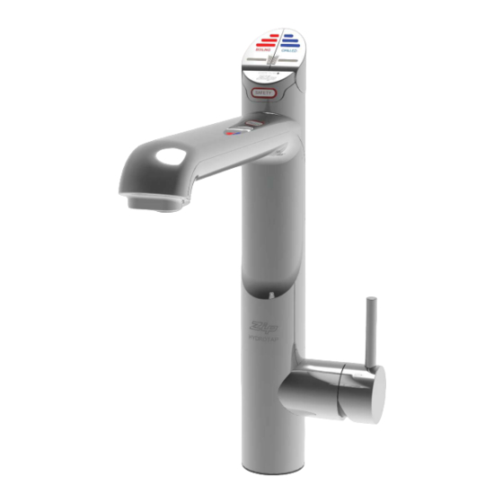
AIO Tap
Residential Chilled Sparkling model
Affix Model Number Label
Here
Residential Boiling Chilled Sparkling model
802005
802005 - Sparkling HT-BCS; CS; AIO; Residential- Installation Instructions - June 2015 - v2.01
Page 1 of 40
Advertisement
Table of Contents

Related Manuals for Zip HydroTap G4


Summary of Contents for Zip HydroTap G4
- Page 1 Installation Instructions Zip HydroTap G4 ® Filtered Boiling, Chilled and Sparkling drinking water for Residential kitchens and tea rooms. Residential CS & BCS HydroTap AIO Tap Residential Chilled Sparkling model Affix Model Number Label Here Residential Boiling Chilled Sparkling model 802005 802005 - Sparkling HT-BCS;...
- Page 2 Tap options The G4 applaince series offers a range of interchangeable taps to suit the customer’s needs These three taps are directly compatible with the G4 under bench unit. The Mixer tap upgrade kits are additional kits that may be used in conjunction with any one of the three taps shown above, to create optional 4-In-1 and 5-In-1 models The All-In-One Tap is a stand alone tap that may be used...
-
Page 3: Table Of Contents
Index HydroTap Specifications Installation check list ........................4 General Product Features ......................5 Important Safety Instructions ....................... 6 Warnings and Regulatory Information ..................7 Major components and Accessories .................... 8 Technical Specification ........................ 9 Before Installation and site requirements ..................10 STEP 1 - Measure and cut all the tap holes before fitting the taps Section 1 - Tap Installation instructions... -
Page 4: Installation Checklist
Installation checklist Before Installation: Read the instructions and check if there is adequate space to mount all of the components. Note: Not all fittings are supplied with the appliance kit. Isolation valves are not supplied. Check the mains water pressure is between 250 - 700kPa Check the water quality to determine if extra filtration will be required. -
Page 5: General Product Features
General Product Features Thank you for purchasing a Zip HydroTap. Please read and follow these instructions carefully to ensure safe and trouble free service. If service is required, please call 1800 460 222 What is the Zip HydroTap ? The Zip HydroTaps are electronically controlled, filtered, Boiling, Chilled and Sparkling water, drinking systems for kitchens and tea rooms. -
Page 6: Important Safety Instructions
Lifting Take care when lifting the Zip HydroTap unit. Some units may exceed safe lifting limits. If you feel this is beyond your personal capabilities, please seek assistance with the lift. The weights of the units are marked on the packaging. -
Page 7: Warnings And Regulatory Information
Important Safety Instructions WARNINGS The Zip HydroTap unit must be earthed. The resistance of the earth connection from each exposed metal part must be less than 1 ohm. All Installation and service work must be completed by trained and suitably qualified Tradespeople. Faulty operation due to unqualified persons working on this product, or any other Zip product may void warranty coverage. -
Page 8: Major Components And Accessories
Major components and accessories Parts supplied Description Accessories Description 1 off 3 HydroTaps Softener with hoses and head assembly (Classic tap shown) 1 off Font Kit for HydroTap Arc & Cube Models Undersink Unit with air and water filters 1 off Font Kit for Classic &... -
Page 9: Technical Specification
Technical Specifications Product covered by these instructions: BCS = Boiling, Chilled and Sparkling, Filtered, = Chilled Sparkling, Filtered = All in One - Mains = All in One - Vented = Disabled lever controls, (Order as an option) Note: chilled water will continue to be dispensed after the rated capacity has been used, although this may be at slightly higher temperature. -
Page 10: Before Installation And Site Requirements
/ or water softener if required. Refer to section 3 & 4, for Installation instructions. • For Zip HydroTap BCS & CS models, a 220-240Vac, 10A GPO will be required. For Zip HydroTap BCSHAV model, a double 220-240Vac, 10A GPO will be required. (One outlet is for the Zip HydroTap and the other for the Booster heater). -
Page 11: Step 1 - Measure And Cut All The Tap Holes Before Fitting The Taps Section 1 - Tap Installation Instructions 1.1 - Hydrotap Classic And Elitetap Installation
Position the tap such that it dispenses into the sink bowl with ample clearance for a cup or tea pot. Alternatively, the tap could be mounted away from the sink using a Zip Font, available as an accessory. Recommended dispensing distance **... - Page 12 HydroTap Classic & Elite EliteTap HydroTap Classic ALL THREAD STAINLESS STEEL BLACK PLASTIC SPACER SPACER SPIDER CLAMP 470mm Tap assembly exploded view and kitchen layout side view. BENCH TOP Ø35mm Apply a light smearing of silicon sealant on the underside of the spacer to ensure a watertight fit. Cut a 35mm hole in the bench / sink top.
- Page 13 Installation Instructions BLACK PLASTIC STAINLESS SPACER STEEL WASHER Fit the STAINLESS STEEL WASHER, SPIDER CLAMP SPIDER CLAMP, AND 6mm NUT. 6mm NUT 35mm hole Note: feed each of the three tubes and electrical cable evenly in between the legs of Pass all the hoses, tubes and USB lead the SPIDER CLAMP when installing.
-
Page 14: Hydrotap Arc/Cube Tap Installations
HydroTap Arc/Cube The HydroTap Arc/Cube has a spout that may be fixed in one of 6 angular positions (depending on the position of the rotary control) and fixed in one of two height positions. The spout is fixed and does not swivel. NOTE: The tube kit must be fitted after the HydroTap has been mounted on the benchtop or sink. - Page 15 Installation Instructions Height adjustment (Fixed position options) 50mm Angular adjustment (Fixed position options) Left Hand Control Right Hand Control NOTE: Position A is not recommended with Boiling water units Mounting (See table on Page 11 ) O-RING BENCH TOP LOWER Ø35mm RUBBER WASHER...
-
Page 16: Mixer Tap Installations
Red band Mixer Out Note: The mixer tap requires a Zip Restrictafl ow External Mains valve, as supplied, to be fi tted in the cold water supply line, from the isolation valve tee... - Page 17 Installation Instructions 1.12 Installing the Mixer Tap (Classic, Arc and Cube) • Fit the O-ring into the recess on the underside of the Mixer tap. (Note: If mounting on an uneven surface, a light smear of silicone on the O-ring will ensure a water tight seal) •...
- Page 18 Installation Instructions 1.13 Typical HydroTap 5-in-1 Installation (see section 5) HydroTap Note: All Mixer Booster silicon tubes Connections must be cut to size. They must have a constant fall back to the unit. MAINS MIXER MIXER BOILING BYPASS VENT BYPASS POWER CORD CHILLED...
-
Page 19: All-In-One Tap Installations
All-In-One Tap Installation 1.14 470mm 1.15 SINK TOP 50mm Cut a 50mm hole in the bench / sink top. Note: make sure the tap location will allow the nozzle to drain into the sink. (See Page 11) Installation Procedure • Fit the seal ring to the base of the tap and If mounting on an uneven surface, apply a light smear of silicone sealant to ensure a watertight seal •... - Page 20 Installation Instructions 1.16 Clamp Block markings and silicon tube positions, viewed from underneath WHITE mark BLUE mark BLUE mark RED mark SILICON TUBES USB CABLE AIO Vented assy AIO Mains assy CLAMP BLOCK O-RING 1.17 Mains IN To Mixer From HWS Mains IN FIXING NUT connection...
- Page 21 Installation Instructions Typical Vented assembly Vented braided hose positions 1.18 WHITE Mains IN • Screw the braided hoses into the extension tubes. Ensure the o-rings CLAMP RED from are lubricated prior to BLOCK Mixer OUT assembly and that the BLUE to braided hoses, with Mixer IN coloured markings,...
- Page 22 Restrictaflow valve Note: The All-In-One vented taps require a Zip Restrictafl ow valve and Tee piece, as supplied, to be fi tted in the cold water supply line, from the isolation valve (Not supplied), to the mixer tap. (See diagrams)
-
Page 23: Section 2 - Ventilation
Section 2 Ventilation When installing air flow ducts, the following tools will be required: • Jigsaw and 12mm Drill • Keyhole or Wall Board saw. Ventilation for All Models Proper air circulation must be provided for all Boiling and Chilled models. The system will operate correctly only if the recommended air gaps are achieved during Installation. -
Page 24: Cutout Details
Ventilation The following instructions are critical if there is insufficient cupboard air circulation. If the air flow, using the silicon door buffers, is insufficient, it will be necessary to fit a standard HydroTap vent kit, which ensures heat dissipation through natural convection via installed vents. For high use applications, where the cupboard space temperature is near 35°C, or higher, the inlet vent (See Item B below) and silicon buffers, need to be fitted. - Page 25 Ventilation Typical Cut out procedure for Mark out and cut the air inlet and door outlet holes as shown Ensure the air inlet vent and air outlet vent are positioned at opposite ends of the same cupboard space. Fit the inlet vent, as shown and secure with 5 screws If required, fit the outlet vent, as shown in the hottest part (top) of the cupboard and secure with 4 screws Air inlet vent...
-
Page 26: Install The Booster Heater (If Required) Section 3 - Booster Heater Installation 3.1 - Booster Heater Specifications And Installation
It is intended to provide pre heating of water before it enters the Zip HydroTap G4 boiling tank. The Booster is supplied with the BCSHAV model. However, it may be later installed, as an accessory for the BCS model, to increase its delivery. - Page 27 Booster Installation Installation Procedure Site requirements • Appliance must only be installed in a frost-free area. Never expose appliance to frost. • The Appliance is designed for wall mounted Installation and must to be installed with water connectors facing upwards. •...
- Page 28 ‘Bypass Out’ fitting to the water inlet of the booster unit (Marked Blue) and from the outlet of the booster unit (Marked Red) to the ‘Bypass IN’ fitting on the Zip HydroTap unit. Avoid exerting any mechanical pressure on the appliance. This can be achieved by applying a spanner on the flats of the inlet and outlet connections when tightening the braided hose connectors.
-
Page 29: Step 4 - Fit The Co Gas Cylinder Section 4 - Co Cylinder 4.1 - Connect And Secure The Co Gas Cylinder
Section 4 Cylinder WARNING: This cylinder mus be installed in an open plan area or in an enclosed room, with a volume no less than 20m If more than 1 gas cylinder containing CO is present within the same location, the recommended ventilated area should be in proportion to the number of gas cylinders stored in that location. - Page 30 Connections & Leak Testing pressure set zone: 2.7-3.0 bar IMPORTANT: After replacing a bottle or after making a gas connection, check for gas leaks: Stage1: Turn the gas OFF Using soapy water applied with a sponge, or with a brush, cover all of the gas joints with a liberal amount of suds.
-
Page 31: Section 5 - Undersink Unit Installation
The diverter bypass valve allows the user to choose to have the boiling feed water bypass the internal filter and only be filtered by the external filtration. This diverter valve is located at the rear panel of the Zip HydroTap undersink unit on the filter door side, see the image below. -
Page 32: Model Bcs
Installation Instructions Model BCS Note: All silicon tubes must be cut to size. They must have a constant fall back to the Leave the unit. RED caps ON unless fitting a Mixer MAINS MIXER MIXER BOILING BYPASS VENT BYPASS POWER CORD CHILLED SPARKLING... -
Page 33: Model Cs
Installation Instructions Model CS Note: All silicon tubes must be cut to size. They must have a constant fall back to the unit. MAINS SPARKLING CHILLED POWER OUTLET OUTLET CORD Note: - Mains hose length is 750mm - Plug and Cord length is 1800mm Position the under Max. -
Page 34: Model Bcsha - Aio Mains
Installation Instructions Model BCSHA All-In-One (Mains) Note: All silicon tubes must be cut to size. They must have a constant fall back to the Leave the unit. RED caps ON unless fitting a Mixer MAINS MIXER MIXER BOILING BYPASS VENT BYPASS POWER CORD CHILLED... -
Page 35: Model Bcshav - Aio Vented
(Supplied) Note: The All-In-One vented taps require a Zip Restrictafl ow valve and Tee piece, as supplied, to be fi tted in the cold water supply line, from the isolation valve (Not supplied), to the mixer tap. (See diagrams) Note:... -
Page 36: Section 6 - Commissioning
Section 6 Commissioning The HydroTap is now ready to be commissioned. • Turn ON the water and gas and check for any leaks. • Turn the power ON at the GPO and at the side of the undersink unit • If fitted, ensure the Booster is turned OFF. (The Booster is commissioned, later, at section 6.4) •... -
Page 37: Boiling Calibration
Commissioning OPEN Position Stop cock operation CLOSED Position Boiling Calibration (Boiling models) • Press the calibration button and the system will commence the Boiling calibration procedure. This will take approx 5-6 minutes. Booster • Upon completion, a Booster reminder screen will appear and allow you to return home by pressing the [Home] button. -
Page 38: Sensor Calibration
Commissioning To enabled when a Booster unit is installed. BC Sparkling 10:30 Wed 14, Nov 2013 1. Press the [MENU] button for main menu. 2. Press the [Install] button. Booster Disable Enable 3. Press the [Booster] button. 4. In the next screen, press button to enable the Booster. -
Page 39: Trouble Shooting
Flow Sensor Fault Internal fault Call Zip Service Call an electrician, a plumber, or Zip for a free call in Australia on 1800-638-633 for assistance, service, spare parts or enquiries. End of Life Disposal In order to help preserve our environment we ask that you dispose of this product correctly. Please contact your local city council for collection centre details. -
Page 40: Contact Details
The standard cup referred to in this publication is 167 ml (6 fl oz). The standard glass is 200 ml (7 fl oz). The terms “Zip” and “HydroTap” are registered trade marks of Zip Heaters (Aust) Pty Ltd. Zip products described in this publication are manufactured under one or more of the following patents: AU675601, AU637412, AU635979, GB0422305, GB2065848, US4354049, US5103859, US5099825 and SA2006/08043.
Need help?
Do you have a question about the HydroTap G4 and is the answer not in the manual?
Questions and answers