Advertisement
Quick Links
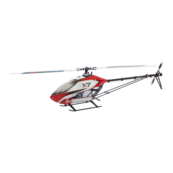
組み立て説明書
V 2.0
スペック
全長(キャノピー含む) : 1385 mm
ローター回転直径 : 1560~1620 mm
メインブレード長 : 690~720 mm
全高 : 415 mm
横幅 : 200 mm
テールブレード長 : 105mm
1560~1620 mm
290 mm
690~720 mm
テールローター回転直径 : 290 mm
ドライブギアレシオ (16T): 8.18 : 1 : 4.71
415 mm
飛行時間 : 7~8 分 (3D フライト)
燃料タンク : 660cc
1385 mm
総重量 : 4400g ±3%
200 mm
© 2014
MADE IN TAIWAN
Advertisement

Subscribe to Our Youtube Channel
Related Manuals for GAUI NX7


Summary of Contents for GAUI NX7
- Page 1 組み立て説明書 V 2.0 スペック 全長(キャノピー含む) : 1385 mm ローター回転直径 : 1560~1620 mm メインブレード長 : 690~720 mm 全高 : 415 mm 横幅 : 200 mm テールブレード長 : 105mm 1560~1620 mm 290 mm 690~720 mm テールローター回転直径 : 290 mm ドライブギアレシオ (16T): 8.18 : 1 : 4.71 415 mm 飛行時間...
- Page 2 Code Spare Part Number We recommend downloading and using the latest manual from Official size specs. M2x4 x3 pcs GAUI website’s download area. 数量 サイズスペック Quantity This product is for a radio controlled (RC) helicopter. Improper operation, maintenance or assembly can potentially cause...
- Page 3 Thank you for purchasing GAUI RC Helicopter from Tai Shih Hobby Corporation (TSH). We hope you will enjoy the joy of flight. In order to understand full assembly sequences, this instruction manual show the assembly information of this model, even though some elements might be supplied as pre-assembled.
-
Page 4: Academy Of Model Aeronautics (Ama)
The Academy of Model Aeronautics (AMA) is a national organization representing modelers in the United States. Please refer to the National Model Aircraft safety code from AMA Member Manual for details: http://www.modelaircraft.org/files/memanual.pdf Partially reprinted rules that are especially pertinent for Radio Controlled flight: RADIO CONTROL 1. - Page 5 1. Use CA glue to fix the on the frame. 全てのネジ部分にネジロック剤を添付 All Screws on side plates should 1.CAグル—を使用し をフレームに接着します。 be applied with thread locker. #073001 #0Z1303 フレームアッセンブリ Frame assembly...
- Page 6 1. Assemble Main Shaft Mount as figure shows. 全てのネジ部分にネジロック剤を添付 全てのネジ部分にネジロック剤を添付 2. Cut the rubber ring in half and use CA glue to stick the half ring on the All Screws on side plates should be applied with thread locker. 1.メインシャフトマウント組み立ては以下のイメージを参考に行います。 2.ラバーリングを半分にカットし瞬間接着剤で ...
- Page 7 1. The metal servo mount can be moved horizontal direction and 全てのネジ部分にネジロック剤を添付 please adjust the swashplate by following P.38. All Screws on side plates should 2. Insert bearing to Starter Shaft Bearing Mount. be applied with thread locker. 3. Assemble reinforcement frame as figure. 4.
- Page 8 1. Use apply anaerobic adhesive to secure the M3 x 12 in the post. 全てのネジ部分にネジロック剤を添付 2. Please tight up the M3x20 screws AFTER P.26 has been done. All Screws on side plates should be applied with thread locker. 1. 嫌気性接着剤を使用しM3 x 12 ポストを固定 2.
- Page 9 Tight M3x8 after P.26 has been done. 全てのネジ部分にネジロック剤を添付 All Screws on side plates should M3 x 8はP.26が完了後に締め付けます。現時点では仮固定とします。 be applied with thread locker. M3x6 M3x8 26.4mm #0R2305 #0R3306 #0R3308 M3x5 M3x6 M3x8 x4 pcs x3 pcs x1 pcs #073207 #073010 #073238 フレームアッセンブリ...
- Page 10 1. Assemble Push-rod adapt. 全てのネジ部分にネジロック剤を添付 2. Install Push-rod adapt to the frame and note the direction of All Screws on side plates should be applied with thread locker. Push-rod adapt. 3. Apply anaerobic adhesive to glue M3x12 into the post. 1.
- Page 11 The metal servo mount can be moved horizontal direction and 全てのネジ部分にネジロック剤を添付 please adjust the swashplate by following P.38. All Screws on side plates should be applied with thread locker. メタルサーボマウントは前後方向に移動が可能です。 P.38を参考にスワッシュプレートに合わせてください。 Step 1. ステップ1. adjustable for horizontal direction. 水平方向に調整 #0R2304 #0R2305 #0R2306 M3x4...
- Page 12 Apply anaerobic adhesive to glue M3x12 in the post. 全てのネジ部分にネジロック剤を添付 All Screws on side plates should 嫌気性接着剤を添付しM3 x12をポストに入れます。 be applied with thread locker. Step 1. ステップ1. #0R2305 #0R1306 #0R4312 M3x5 M3x6 M3x12 x4 pcs x2 pcs x12 pcs #0A8053 #073237 P.11 フレームアッセンブリ...
-
Page 13: Engine Assembly
1. Assemble fan and hub as right figure and install it to engine. 全てのネジ部分にネジロック剤を添付 2. Please tight the crank nut first and then tight screw M3x10. All Screws on side plates should be applied with thread locker. 1. ファンとハブを右の画像を参考に組み立てた後エンジンにインストールします。 2. 先にクランクナットを締めつけてからM3 x10のスクリューを締めこみます。 Step 1. - Page 14 1. Install and then tight after. 全てのネジ部分にネジロック剤を添付 2. Secure to the hub by using screw M4x8. All Screws on side plates should be applied with thread locker. 1. 先に と を取り付けてから を締めます 2. M4 x 8を使用し をハブに取り付けます。 M4x8 Step 1. ステップ1.
- Page 15 1. Install starter shaft head to starter shaft and secure it by using 全てのネジ部分にネジロック剤を添付 two M4x4 screws. All Screws on side plates should be applied with thread locker. 2. Please check and test the smooth of operation of starter shaft after complete the installment.
- Page 16 1. Install fan set to engine and place the engine to the body. 全てのネジ部分にネジロック剤を添付 2. Screw M3x5 and M3x8 to two side of frame. All Screws on side plates should be applied with thread locker. 1. ファンセットをエンジンボディへ取り付けます。 2. M3 x 5 と M3 x 8 をフレーム両側に取り付けます。 Step 1.
- Page 17 1. Adjust proper angle of fuel tank to fit into the frame and secure it by two 全てのネジ部分にネジロック剤を添付 M3x35 screws as the picture shows. All Screws on side plates should be applied with thread locker. 1. タンクをズラしたりしながらフレームにタンクを取り付け、M3 x 35のスクリューで固定します。 図を参考にします。 26.4mm 26.4mm #0R7335...
- Page 18 1. Assemble bottom frame and landing gear. 全てのネジ部分にネジロック剤を添付 All Screws on side plates should 1. ボトムフレームとランディングギアを組み立て be applied with thread locker. M3x5 26.4mm M3x3 M3x14 M3x5 M3x14 M3x8 #0R2305 #0R2308 M3x5 M3x8 x3 pcs x2 pcs 8.00 #0R2314 #0R4303 #073004 M3x14 M3x3 x4 pcs...
- Page 19 Install to two side of frame. 全てのネジ部分にネジロック剤を添付 All Screws on side plates should をフレーム両側に取り付け be applied with thread locker. #0R2306 M3x6 x14 pcs #073006 P.18 Frame assembly フレームアッセンブリ...
- Page 20 Do not over tight the screws when install to prevent thread damage. 全てのネジ部分にネジロック剤を添付 All Screws on side plates should を締め付ける際は締めすぎないように注意してください。樹脂パーツにはネジロック剤は使用しません。 be applied with thread locker. Canopy holder can be removed or keeped キャノピーホルダーは取り除いてもそのままでも構いません #0R7308 x14 pcs #073404 P.19 フレームアッセンブリ Frame assembly...
- Page 21 1.Insert the fixing pin (4.5mm side) into the 全てのネジ部分にネジロック剤を添付 2.Insert the into the and apply CA glue to fix it, All Screws on side plates should pay attention to the direction of the be applied with thread locker. 1. へ固定ピン(4.5mmの方)を挿入 2.
- Page 22 Make sure the hole on tail gear case is align to M3x6 screw before tighten. 全てのネジ部分にネジロック剤を添付 テールギアケースの M3 x 6 を占めこむ前に,固定穴の中心をよく確認してから締め込みます。 All Screws on side plates should be applied with thread locker. ベアリング 12x21x5 固定穴 fixing hole. M3x6 ベアリング 6x13x5 ピン...
- Page 23 1.If the can not move smoothly,adjust the M3x6 screw on 全てのネジ部分にネジロック剤を添付 All Screws on side plates should がスムーズに動かない場合は の M3 x6 を調整します。 be applied with thread locker. M3x3 P8x10x3.2 2x13 M3x6 Bearing 8x12x3.5 出荷時組み立て済み is already assemblied in factory チューブ 2.5x5.8 M2x2 M3x5...
- Page 24 1.Do not over tighten the M2x10 screw. 全てのネジ部分にネジロック剤を添付 All Screws on side plates should 1. M2 x 10 締めすぎに注意 be applied with thread locker. N3x5.5 ベアリング 5x10x4 スラストベアリング 5x10x4 M4x4 M3x16 ワッシャー 5.1x7x0.7 M2x10 N3x5.5 N3x5.5 チューブ 2x2.95x4.3 M3x10 M3x25 内径大...
-
Page 25: Main Gear Assembly
One way bearing need to maintain with bearing grease regularly. 全てのネジ部分にネジロック剤を添付 All Screws on side plates should ワンウエイベアリングは定期的にメンテナンスが必要です。 be applied with thread locker. M3x7 ベアリング 15x24x5 W15.1x18x2 M3x8 #0R1308 #0R3307 M3x8 M3x7 x6 pcs x6 pcs #073405 #074202 #074205 #073406 P.24 Main gear assembly メインギアアッセンブリ... - Page 26 Use W12.1x17x1.2 washer for main gear. If the tolerance between gears is not right, use W12.1x17x0.2 and W12.1x17x0.3 washers to adjust the tolerance. Proper tolerance between gears is around 0.1mm. W12.1 x 17 x 1.2 ワッシャーをメインギアに挿入します。 隙間が適正でない場合は,W12.1 x 0.2 と W12.1 x 17 x 0.3 ワッシャーを使用し隙間を調整します。 適正な隙間はおおよそ...
- Page 27 1. Make torque tube tail boom(assembled in P.23) through 全てのネジ部分にネジロック剤を添付 to frame body, and make sure the 14T front bevel gear fixing All Screws on side plates should be applied with thread locker. pin is in the right position. 2. Tight M3x20 & M3x8 screws after checking 14T gear and 66T gear are working good together by spinning the main gear.
- Page 28 After assemble tail push rod, attach on it and make sure the 全てのネジ部分にネジロック剤を添付 push-rod adapt is vertical to tail pus rod. All Screws on side plates should be applied with thread locker. The lever will parallel with tail push rod. テールプッシュロッドを組み立て後、 を取り付けプッシュロッドはレバーと垂直になるようにします。...
- Page 29 Assemble and install & as right figure. 全てのネジ部分にネジロック剤を添付 Install and Using AB glue to glue support rod head and support rod. All Screws on side plates should be applied with thread locker. と を右の図を参考にし取り付けます。 Step 1. ステップ1. はサポートロッドとロッドヘッドにABグル—を使用し取り付けます。 M3x6 4.2x8x0.4 ワッシャー M4x8 M3x10 N2x4...
- Page 30 1. Secure to support rod as picture shows. 全てのネジ部分にネジロック剤を添付 All Screws on side plates should 1. をイメージを参考にサポートロッドに取り付けます。 be applied with thread locker. N2x4 M2x10 #0R8204 #0R1210 N2x4 M2x10 x4 pcs x4 pcs #0A3002 P.29 テールケースアッセンブリ Tail case assembly...
-
Page 31: Swashplate Assembly
全てのネジ部分にネジロック剤を添付 All Screws on side plates should be applied with thread locker. M2x3 ボール M3x8 ベアリング 2x6x3 M2x10 ベアリング M2x3 30x42x7 #0R1203 #0R1210 M2x3 M2x10 x4 pcs x1 pcs #0R2203 #0R1308 M2x3 M3x8 x2 pcs x1 pcs #0B1201 #0A8622 #0B1304 P.30 Swashplate assembly スワッシュプレートアッセンブリ... - Page 32 Make sure M5x12 is tighten and glued. 全てのネジ部分にネジロック剤を添付 All Screws on side plates should M5 x 12の締め付けとグル—添付を確認 be applied with thread locker. M3x10 When assembling the rotor head, you can adjust for adequate mesh with W10.2x16x1 or W10.2x16x0.8 & 0.9 washers. ローターヘッド組み立て時は、十分な隙間を好みで調...
- Page 33 Assemble and install washout arm to rotor head. 全てのネジ部分にネジロック剤を添付 All Screws on side plates should ウオッシュアウトアームを組み立てローターヘッドに取り付けます。 be applied with thread locker. ベアリング 3x8x3 ワッシャー 3.1x4.6x1 M3x12 チューブ 3x5x5.1 M3x12 M3x18 #0R2312 #0R2318 #0R4312 M3x12 M3x18 M3x12 x2 pcs x2 pcs x2 pcs #072207 #0A8504...
- Page 34 1. Install blade rotor head to main shaft and tight M4x23 screw then tight M3x10. 2. Adjust to reach main blade grip. (please refer to P. 38) 1. ローターヘッドにメインシャフトを取り付けM4X23締めんでからM3x10を締めます。 2. P.37を参考に を調整します。 N4x7 M4x23 M3x10 Use a stick (<2mm) as tool, insert it into the adjusting hole for adjusting the length of the main blade push rod.
- Page 35 1. Different servo has different length requirement for push rod. 全てのネジ部分にネジロック剤を添付 Please adjust the length for your servo. All Screws on side plates should be applied with thread locker. 2. Refer to P.38. Adjust the length of ball with stand by changing different tube as the picture shows on right down corner.(three different sizes) 1.
- Page 36 1. Different servo has different length requirement for push rod. 全てのネジ部分にネジロック剤を添付 Please adjust the length for your servo. All Screws on side plates should be applied with thread locker. 2. Refer to P.38. Adjust the length of ball with stand by changing different tube as right down picture.(three different sizes) 1.
- Page 37 Install throttle servo 全てのネジ部分にネジロック剤を添付 All Screws on side plates should スロットルサーボインストール be applied with thread locker. M2.6x12 M2x12 N2x4 GAUI throttle push rod スロットルプッシュロッド 90mm 77.4mm 106mm #0R7212 #0R1212 #0R8204 M2.6x12 M2x12 N2x4 x4 pcs x1 pcs x1 pcs #0Z6202 Tail push rod / Throttle servo assembly P.36...
- Page 38 All Screws on side plates should be applied with thread locker. 2.Install (1) and refer to P.27 to do adjustment. 1. プッシュロッドにアルミシースを固定しCAグル—を添付添付し、ボールリンクをインストールします。 2. インストール[1]はP.27を参考に水平になるように調整します。 N2x4 M2x12 Tube M2.6x12 2x3.5x3.5 302mm GAUI 292mm 320.5mm #0R7212 #0R1212 #0R8204 M2.6x12 M2x12 N2x4 x4 pcs x1 pcs...
- Page 39 1. Install servos by referring P.34 to 35 and check the horizontal and vertical. 2. install 1. P.34からP.35を参照し、水平、垂直レベルを確認しサーボをインストール。 2. 取り付け Step 1. Step 2. ステップ1. ステップ2. 3x12 水平 垂直 #0R7312 3x12 x2 pcs #073401 Swashplate Guide / Muffler /Electronics / Canopy installation P.38 スワッシュプレートガイド...
- Page 40 1. Install main blade and muffler 2. Install governor 1. メインブレードとマフラーの取り付け 2. ガバナー取り付け M5x30 N5x8 1. Location of electronics parts are show as follow. 2. Insert R clip to canopy posts to secure canopy. (refer to right picture) 1. 図を参考にエレクトロニクスパーツを搭載 2.
-
Page 41: Spare Parts List
077504 Main Blade Holder Washer Pack メインシャフト 198mm (for NX7) 072210 Main Shaft 198mm (for NX7) カーボンファイバー メインフレーム (2mm) (For NX7) 073001 Carbon Fiber Main Frame (2mm)(for NX7) レインフォースメント フレーム (A) (2mm) (For NX7) 073003 Reinforcement Frame(A)(2mm)(for NX7) レインフォースメント フレーム (B) (2mm) (For NX7) 073004 Reinforcement Frame(B)(2mm)(for NX7) フレーム... - Page 42 CF テール フロントプッシュロッド アップグレード (For NX7) 075214 CF Tail front pushrod upgrade(for NX7) CF テールブーム サポートロッドセット (レッド アノダイズド) (For NX7) 076207 CF Tail Boom Support Rod Set (Red anodized)(for NX7) FORMULA キャノピー (C1 タイプ レッド) (For NX7) 077021 FORMULA Canopy(C1 Type Red)(for NX7)
- Page 43 Screws スクリュー ソケットヘッド キャップスクリュー ブラック (M2x3)x10pcs 0R1203 Socket Head Cap Screw - Black (M2x3)x10pcs ソケットヘッド キャップスクリュー ブラック (M2x5)x10pcs 0R1205 Socket Head Cap Screw - Black (M2x5)x10pcs ソケットヘッド キャップスクリュー ブラック (M2x10)x10pcs 0R1210 Socket Head Cap Screw - Black (M2x10)x10pcs ソケットヘッド キャップスクリュー ブラック (M2x12)x10pcs 0R1212 Socket Head Cap Screw - Black (M2x12)x10pcs ソケットヘッド...
- Page 44 GAUI 製品購入後のお問い合わせは【ガウイ ジャパン】まで GAUI JAPAN www.gaui.com.tw E-mail: gaui@gaui.com.tw TEL: +886-2-86305567 FAX: +886-2-26105567 E-mail: customerservice@gaui.jp No.118, Ren’ai Rd., Bali Dist., TEL: 050-5539-0883 〒273-0864 千葉県船橋市北本町2-57-2 1F,2F New Taipei City 249, Taiwan © 2014 MADE IN TAIWAN...
Need help?
Do you have a question about the NX7 and is the answer not in the manual?
Questions and answers