
Related Manuals for Allied Telesis CentreCOM FS980M Series


Summary of Contents for Allied Telesis CentreCOM FS980M Series
- Page 1 CentreCOM FS980M Series ® Fast Ethernet Switches AlliedWare Plus™ FS980M/9 FS980M/9PS FS980M/18 FS980M/18PS FS980M/28 FS980M/28PS FS980M/28DP FS980M/52 FS980M/52PS Quick Installation Guide 613-003080 Rev A...
-
Page 2: Table Of Contents
Introduction This Quick Installation Guide contains a short version of the installation instructions for the CentreCOM FS980M Series of Fast Ethernet Managed Access Switches. For more instructions, refer to the FS980M Series Fast Ethernet Switch Series Installation Guide on the Allied Telesis web site at www.alliedtelesis.com/us/en/ services-support. - Page 3 FS980M/18 FS980M/18PS FS980M/28 FS980M/28PS FS980M/28DP FS980M/52 FS980M/52PS CentreCOM FS980M Series Quick Installation Guide...
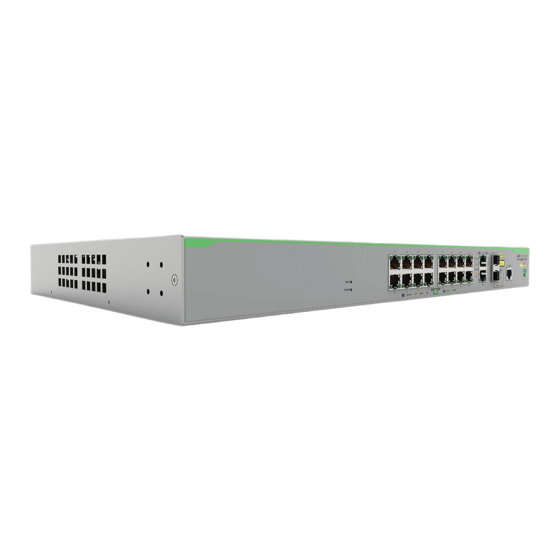
- Page 4 1 to 48 FS980M/52PS 1 to 48 Here are the 10/100/1000Mbps Ethernet copper ports. Switch 10/100/1000Mbps Copper Ports FS980M/9 9R (Combo) FS980M/9PS 9R (Combo) FS980M/18 17R and 18R (Combo) FS980M/18PS 17R and 18R (Combo) FS980M/28 CentreCOM FS980M Series Quick Installation Guide...
- Page 5 PoE+ power. When both power supplies are receiving power, one power supply is active and the other is redundant power. If the active power supply loses power, the redundant power supply automatically becomes active and supplies system and PoE+ power for the switch. CentreCOM FS980M Series Quick Installation Guide...
-
Page 6: Poe+ Power Budgets
Switches have one or two combo ports. The combo ports have one 10/100/1000Mbps Ethernet copper port and one SFP transceiver port. The Ethernet copper ports have the letter “R” for “Redundant” on the front panels of the switches. The combo ports are listed here. CentreCOM FS980M Series Quick Installation Guide... -
Page 7: Vcstack Feature
In contrast, the ports of a static trunk in a stack can be from different switches in the same stack. FS980M For instructions on VCStack, refer to the CentreCOM AlliedWare Plus Series Command Reference for CentreCOM FS980M Series Quick Installation Guide... -
Page 8: Beginning The Installation
Note: The symbol indicates that a translation of the safety statement is available in the PDF document “Translated Safety Statements” on the Allied Telesis website at www.alliedtelesis.com/us/en/documents/translated-safety- statements. Warning: Class 1 Laser product. L1 Warning: Do not stare into the laser beam. L2 Warning: Power cord is used as a disconnection device. - Page 9 E40 Installation Options Here are the installation options. Table Wall Standard 19-inch equipment rack CentreCOM FS980M Series Quick Installation Guide...
- Page 10 Eight bracket screws M4 x 6.8mm flat-head screws Four equipment rack screws Four plastic feet Four wall mount M4 x 32mm round-head screws wood screws round-head Four wall mount anchors 6mm x 30mm nylon anchors CentreCOM FS980M Series Quick Installation Guide...
- Page 11 You should position the device so that it can be screwed into the wall’s framing timber or equivalent structural element. The power outlet should be located near the switch and be easily accessible. CentreCOM FS980M Series Quick Installation Guide...
-
Page 12: Installing The Switch
You need the following items to install the switch in an equipment rack: Two equipment rack brackets (included with the switch) Eight bracket screws (included with the switch) Four standard equipment rack screws (included with the switch) CentreCOM FS980M Series Quick Installation Guide... - Page 13 M4mm x 6.8mm screws included with the switch. 4. Have another person hold the switch in the equipment rack while you secure it using the four standard equipment rack screws. 5. Go to “Ports” on page 17. CentreCOM FS980M Series Quick Installation Guide...
- Page 14 Stud finder for a wooden wall, capable of identifying the middle of wall studs and hot electrical wiring (not provided) Drill and 1/4” carbide drill bit for a concrete wall (not provided) CentreCOM FS980M Series Quick Installation Guide...
- Page 15 For all other FS980M Switches, go to step 6. 3. Turn over the switch on a table. 4. Attach two feet at the corners opposite the brackets. CentreCOM FS980M Series Quick Installation Guide...
- Page 16 7. Place the switch on a table. 8. Use the stud finder to check for hot electrical wires at the locations of the screw holes. Warning: Do not install the switch on a wall near hot electrical wires. CentreCOM FS980M Series Quick Installation Guide...
- Page 17 Observe the following guidelines when connecting Ethernet copper cables to the ports on the switch: The connectors on the cables should fit snugly into the ports, and the tabs should lock the connectors into place. CentreCOM FS980M Series Quick Installation Guide...
- Page 18 You can install SFP transceivers while the switch is powered on. For a list of supported transceivers, refer to the product’s data sheet on the Allied Telesis web site at www.alliedtelesis.com. The operational specifications and fiber optic cable requirements are included with the transceivers.
- Page 19 4. Connect the fiber optic cable to the transceiver. The connector should fit snugly into the port, and the tab should lock the connector into place. 5. Repeat this procedure to install additional transceivers. 6. Go to “Powering On the Switch” on page 20. CentreCOM FS980M Series Quick Installation Guide...
- Page 20 5. Wait two minutes for the switch to initialize its management software. 6. Verify that the Power LED is green. If the LED is OFF, go to “Troubleshooting” next. CentreCOM FS980M Series Quick Installation Guide...
- Page 21 Flashing amber The switch is loading the firmware. The switch is operating normally or the switch’s power is off. Power LED Solid green The switch is receiving AC power. The switch is not receiving power. CentreCOM FS980M Series Quick Installation Guide...
- Page 22 - The LEDs are turned off. To turn on the LEDs, use the eco-friendly button. Duplex Mode LEDs - Non-PoE+ Switches Solid Green The port is operating in full-duplex mode. The port is operating in half-duplex mode, or the LEDs are turned off. CentreCOM FS980M Series Quick Installation Guide...
- Page 23 Duplex Mode LEDs Link/Activity LEDs Link/Activity LEDs Solid Green The port has established a link at 1000Mbps to a network device. Flashing Green The port is receiving or transmitting frames at 1000Mbps. CentreCOM FS980M Series Quick Installation Guide...
- Page 24 The port is receiving or transmitting frames at Green 1000Mbps. Solid The port has established a link to a network device at amber 100Mbps. Flashing The port is receiving or transmitting frames at amber 100Mbps. CentreCOM FS980M Series Quick Installation Guide...
- Page 25 Console port are 9600, 19200, 38400, 57600, and 115200 bps.) Data bits: 8 Parity: None Stop bits: 1 Flow controller: None 4. Press Enter. You are prompted for a user name and password. CentreCOM FS980M Series Quick Installation Guide...
- Page 26 5. Wait two minutes for the switch to start the management software The switch in now in standalone mode. The SFP S1 and S2 ports are now regular Ethernet ports. 6. You can now cable the SFP S1 and S2 transceiver ports. CentreCOM FS980M Series Quick Installation Guide...
- Page 27 Check the port’s PoE+ LED. Refer to “10/100Mbps Ethernet Copper Port LEDs” on page 22. If the LED is flashing amber, the switch cannot support additional PoE+ devices device because it is already providing its maximum power to other devices. CentreCOM FS980M Series Quick Installation Guide...
- Page 28 Allied Telesis, Inc. reserves the right to make changes in specifications and other information contained in this document without prior written notice. The information provided herein is subject to change without notice. In no event shall Allied Telesis, Inc. be liable for any incidental, special, indirect, or consequential damages whatsoever, including but not limited to lost profits, arising out of or related to this manual or the information contained herein, even if Allied Telesis, Inc.
Need help?
Do you have a question about the CentreCOM FS980M Series and is the answer not in the manual?
Questions and answers