Table of Contents
Advertisement
Quick Links
Advertisement
Table of Contents

Subscribe to Our Youtube Channel
Related Manuals for Allied Telesis FS970M Series


Summary of Contents for Allied Telesis FS970M Series
- Page 1 FS970M Series Fast Ethernet Switches AT-FS970M/8 AT-FS970M/8PS AT-FS970M/8PS-E AT-FS970M/16F8-LC AT-FS970M/16F8-SC AT-FS970M/24C AT-FS970M/24F AT-FS970M/24LPS AT-FS970M/24PS AT-FS970M/48 AT-FS970M/48PS Installation Guide 613-001902 Rev. B...
- Page 2 Allied Telesis, Inc. has been advised of, known, or should have known, the...
- Page 3 Electrical Safety and Emissions Standards This product meets the following standards. U.S. Federal Communications Commission Radiated Energy Note: This equipment has been tested and found to comply with the limits for a Class A digital device pursuant to Part 15 of FCC Rules.
- Page 4 Translated Safety Statements Important: The indicates that translations of the safety statement are available in the PDF document “Translated Safety Statements” posted on the Allied Telesis website at www.alliedtelesis.com/support.
-
Page 5: Table Of Contents
Table of Contents Preface ............................11 Document Conventions ..............................12 Contacting Allied Telesis ..............................13 Chapter 1: Overview ........................15 Features ..................................16 FS970M Models ..............................16 10/100 Mbps Twisted Pair Ports ...........................16 Fiber Optic Ports ..............................16 Power over Ethernet .............................17 10/100/1000 Mbps Twisted Pair Ports ........................17 SFP Slots ................................17... - Page 6 Contents Power Over Ethernet ..............................39 PoE Standards ..............................39 Powered Device Classes............................39 Power Budget ............................... 40 Port Prioritization ..............................41 Wiring Implementation............................42 eco-friendly Button............................... 43 LEDs .................................... 44 10/100Base-TX Twisted Pair Port LEDs ......................44 10/100/1000Base-T Twisted Pair Port LEDs......................45 100Base-FX Port LEDs ............................
- Page 7 Figure 8: Back Panels of the Single Power Supply Switches ....................28 Figure 9: Back Panel of the Dual Power Supply Switches ....................29 Figure 10: FS970M Series Management Panels........................30 Figure 11: Model Naming Conventions for the Twisted Pair Switches .................31 Figure 12: Model Naming Conventions of the Fiber Optic Switch ..................31 Figure 13: 10/100Base-TX Port LEDs ..........................44...
- Page 8 Figures...
- Page 9 List of Tables Table 1: Hardware Features of the 8-port Switches ......................19 Table 2: Hardware Features of the 24 and 48-port Switches ....................21 Table 3: Hardware Features of the AT-FS970M/16F8-LC Fiber Optic Switch ..............24 Table 4: General Specifications of AT-FS970M/16F8-LC and AT-FS970M/16F8-SC Fiber Optic Ports ......27 Table 5: Model Naming Conventions for the Twisted Pair Switches ...................31 Table 6: Model Naming Conventions for the AT-FS970M/16F8-LC Fiber Optic Switch ............32 Table 7: Twisted Pair Cable Requirements for the 10/100Base-TX Ports ................34...
- Page 10 Tables...
-
Page 11: Preface
Preface This guide contains the installation instructions for the FS970M Series of Fast Ethernet switches. The preface contains the following sections: “Document Conventions” on page 12 “Contacting Allied Telesis” on page 13... -
Page 12: Document Conventions
Preface Document Conventions This document uses the following conventions: Note Notes provide additional information. Caution Cautions inform you that performing or omitting a specific action may result in equipment damage or loss of data. Warning Warnings inform you that performing or omitting a specific action may result in bodily injury. -
Page 13: Contacting Allied Telesis
FS970M Series Installation Guide Contacting Allied Telesis If you need assistance with this product, you may contact Allied Telesis technical support by going to the Support & Services section of the Allied Telesis web site at www.alliedtelesis.com/support. You can find links for the following services on this page: ... - Page 14 Preface...
-
Page 15: Chapter 1: Overview
Chapter 1 Overview This chapter contains the following sections: “Features” on page 16 “Switches with Eight Twisted Pair Ports” on page 19 “Switches with 24 or 48 Twisted Pair Ports” on page 21 “Fiber Optic Switch” on page 24 ... -
Page 16: Features
Overview Features Here are lists of the switches and their features: FS970M Models Here are the FS970M Series of Fast Ethernet switches: T-FS970M/8 AT-FS970M/8PS AT-FS970M/8PS-E AT-FS970M/16F8-LC AT-FS970M/16F8-SC AT-FS970M/24C AT-FS970M/24F AT-FS970M/24LPS AT-FS970M/24PS ... -
Page 17: Power Over Ethernet
The SFP slots and 10/100/1000Base-TX twisted pair ports are paired together to form combo ports. For information, refer to “SFP Slots” on page 37. Note SFP transceivers must be purchased separately. For a list of supported transceivers, contact your Allied Telesis distributor or reseller. -
Page 18: Leds
Overview LEDs Here are the port LEDs: Duplex mode and link/activity LEDs for the twisted pair ports Link/activity LEDs for the 100Base-FX fiber optic ports Link/activity LEDs for the SFP slots eco-friendly button turns off the LEDs to conserve electricity Installation Here are the installation options: Options... -
Page 19: Switches With Eight Twisted Pair Ports
FS970M Series Installation Guide Switches with Eight Twisted Pair Ports Here are the 8-port twisted pair models in the FS970M Series: AT-FS970M/8 AT-FS970M/8PS AT-FS970M/8PS-E Hardware Table 1 lists the hardware features of the 8-port switches. Features Table 1. Hardware Features of the 8-port Switches... -
Page 20: Front Panels
Overview Front Panels The front panels of the 8-port switches are shown in Figure 1. AT-FS970M/8 AT-FS970M/8PS AT-FS970M/8PS-E Figure 1. Front Panels of the 8-port FS970M Switches Front Panel Figure 2 identifies the Fast and Gigabit Ethernet networking ports and the SFP slots on the 8-port switches. -
Page 21: Switches With 24 Or 48 Twisted Pair Ports
FS970M Series Installation Guide Switches with 24 or 48 Twisted Pair Ports The FS970M Series Switches with 24 or 48 twisted pair ports are listed here: AT-FS970M/24C AT-FS970M/24LPS AT-FS970M/24PS AT-FS970M/48 AT-FS970M/48PS Hardware Table 2 lists the hardware features of the switches. -
Page 22: Front Panels
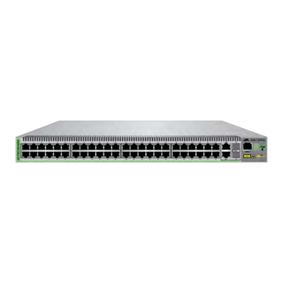
Overview Front Panels The front panels of the 24 and 48-port switches are shown in Figure 3. AT-FS970M/24C AT-FS970M/24PS AT-FS970M/24LPS AT-FS970M/48 AT-FS970M/48PS Figure 3. Front Panels of the 24 and 48-port Switches... -
Page 23: Front Panel Components
FS970M Series Installation Guide Front Panel Figure 4 identifies the Fast and Gigabit Ethernet networking ports and the SFP slots on the 24 and 48-port switches. Components 10/100Base-TX Ports Management Panel Combo 10/100/1000Base-T Ports and SFP Slots 10/100Base-TX Ports Management... -
Page 24: Fiber Optic Switch
Overview Fiber Optic Switch The FS970M Series has two fiber optic switches, the AT-FS970M/16F8- LC and AT-FS970M/16F8-SC. Hardware Table 3 lists the hardware features of the fiber optic switch. Features Table 3. Hardware Features of the AT-FS970M/16F8-LC Fiber Optic Switch... -
Page 25: Front Panel
FS970M Series Installation Guide Front Panel The front panel of the AT-FS970M/16F8-LC Switch is shown in Figure 5. AT-FS970M/16F8-LC 100Base-FX Fiber 10/100Base-TX Management Optic Ports with Twisted Pair Panel Duplex LC Connectors Ports Combo 10/100/1000Base-T Ports and SFP Slots Figure 5. Front Panel of the AT-FS970M/16F8-LC Fiber Optic Switch The front panel of the AT-FS970M/16F8-SC Switch is shown in Figure 6. -
Page 26: Figure 7: Front Panel Of The At-Fs970M/24F Fiber Optic Switch
Overview The front panel of the AT-FS970M/24F Switch is shown in Figure 7. AT-FS970M/24F 100Base-FX Fiber Management Optic Ports with Panel Duplex LC Connectors Combo 10/100/1000Base-T Ports and SFP Slots Figure 7. Front Panel of the AT-FS970M/24F Fiber Optic Switch... -
Page 27: Fiber Optic Ports
FS970M Series Installation Guide Fiber Optic Ports Table 4 lists the general specifications of the fiber optic ports on the AT-FS970M/16F8-LC and AT-FS970M/16F8-SC Switches. Table 4. General Specifications of AT-FS970M/16F8-LC and AT-FS970M/16F8-SC Fiber Optic Ports Feature 16F8-LC 16F8-SC Number of Fiber Optic... -
Page 28: Back Panels
Overview Back Panels Figure 8 shows the back panels of the single power supply switches. AT-FS970M/8, AT-FS970M/8-E, and AT-FS970M/24C Switches AC Power Connector AT-FS970M/8PS Switch AC Power Connector AT-FS970M/24LPS and AT-FS970M/48 Switches Figure 8. Back Panels of the Single Power Supply Switches... -
Page 29: Figure 9: Back Panel Of The Dual Power Supply Switches
FS970M Series Installation Guide Figure 9 shows the back panel of the dual power supply switches including: AT-FS970M/16F8-LC AT-FS970M/16F8-SC AT-FS970M/24F AT-FS970M/24PS AT-FS970M/48PS Switches AC Power AC Power Connector Connector (Power Supply 2) (Power Supply 1) -
Page 30: Management Panels
Overview Management Panels Figure 10 identifies the components in the management panels on the FS970M Fast Ethernet Switches. eco-friendly Button Console System LED Management Port Console Management Port System LED eco-friendly Button Figure 10. FS970M Series Management Panels... -
Page 31: Model Naming Conventions
FS970M Series Installation Guide Model Naming Conventions The hardware features of the switches are represented by the letters and numbers in the model names. The conventions for the twisted pair switches are identified in Figure 11. Figure 11. Model Naming Conventions for the Twisted Pair Switches The conventions are defined in Table 5. -
Page 32: Table 6: Model Naming Conventions For The At-Fs970M/16F8-Lc Fiber Optic Switch
Overview The conventions are defined in Table 6. Table 6. Model Naming Conventions for the AT-FS970M/16F8-LC Fiber Optic Switch Convention Definition This is the product name. This is the number of 100Base-FX fiber optic ports. The letter “F” signifies fiber optic. This is the number of 10/100Base-TX ports. -
Page 33: 10/100Base-Tx Twisted Pair Ports
FS970M Series Installation Guide 10/100Base-TX Twisted Pair Ports The switches have 8, 24, or 48 10/100Base-TX ports. Speed The ports can operate at either 10 or 100 Mbps. The speeds may be set manually using the management software or automatically with Auto- Negotiation (IEEE 802.3u), the default setting. -
Page 34: Maximum Distance
Overview Maximum The ports have a maximum operating distance of 100 meters (328 feet). Distance Power Over The 10/100Base-TX ports on the AT-FS970M/8PS, AT-FS970M/8PS-E, AT-FS970M/24PS and AT-FS970M/48PS Switches support Power over Ethernet Ethernet (PoE), which is a standard whereby DC power is provided by the switch to network devices over the network twisted pair cables. -
Page 35: 10/100/1000Base-T Twisted Pair Ports
FS970M Series Installation Guide 10/100/1000Base-T Twisted Pair Ports The switches have two 10/100/1000Base-T ports. These ports are paired with SFP slots to form combo ports. Speed The ports can operate at 10, 100, or 1000 Mbps. The speeds may be set manually using the management software or automatically with Auto- Negotiation (IEEE 802.3u), the default setting. -
Page 36: Maximum Distance
Overview The MDI and MDI-X settings do not apply when the ports are operating at 1000 Mbps. Maximum The ports have a maximum operating distance of 100 meters (328 feet). Distance Power Over The 10/100/1000Base-T ports on the AT-FS970M/8PS, AT-FS970M/8PS- E, AT-FS970M/24PS and AT-FS970M/48PS Switches do not support Ethernet PoE. -
Page 37: Sfp Slots
The switches support a variety of short and long distance, 100 and 1000 Mbps fiber optic SFP modules. For a list of supported SFP modules, contact your Allied Telesis representative or visit our web site. The two SFP slots are paired with the two 10/100/1000Base-T ports. The combo ports are listed in Table 9. - Page 38 Overview Port speed is an exception to the shared settings of the twisted pair port and SFP slot of a combo port. If you disable Auto-Negotiation on the twisted pair port and set the speed and duplex mode manually, the switch reactivates it when an SFP module establishes a link with an end node.
-
Page 39: Power Over Ethernet
FS970M Series Installation Guide Power Over Ethernet The AT-FS970M/8PS, AT-FS970M/8PS-E, AT-FS970M/24PS, and AT-FS970M/48PS Switches feature Power over Ethernet (PoE) on the 10/ 100Base-TX ports. PoE is used to supply power to network devices over the same twisted pair cables that carry the network traffic. -
Page 40: Power Budget
Overview Table 10. IEEE Powered Device Classes Maximum Power Class Output from a Switch PD Power Range Port 15.4W 0.44W to 12.95W 4.0W 0.44W to 3.84W 7.0W 3.84W to 6.49W 15.4W 6.49W to 12.95W 30.0W 12.95W to 25.5W Note PoE+ Class 4 powered devices (IEEE 802.3at) with a power range of 12.95 to 25.5 watts must use LLDP to identify their power requirements to the switch. -
Page 41: Port Prioritization
FS970M Series Installation Guide Otherwise, the switch powers a subset of the devices, based on port prioritization. The switch can handle different power requirements on different ports. This enables you to connect different classes of PoE equipment to the ports on the switch. -
Page 42: Wiring Implementation
Overview sufficient power to support the critical devices even if it has only one functional power supply. Wiring The IEEE 802.3af standard defines two methods by which a PSE, such as the switch, can transmit DC power over twisted pair cables to PDs. These Implementation methods, known as modes A and B, identify the wire strands the switch should use when sending DC power to a PD. -
Page 43: Eco-Friendly Button
FS970M Series Installation Guide eco-friendly Button You may turn off the port LEDs to conserve electricity when you are not monitoring the switch. The LEDs may be toggled with the eco-friendly button on the front panel of the switch or the ECOFRIENDLY LED and NO ECOFRIENDLY LED commands in the Global Configuration mode of the command line interface. -
Page 44: Leds
Overview LEDs Here are descriptions of the switch’s LEDs. 10/100Base-TX The 10/100Base-TX twisted pair ports have link/activity and duplex mode LEDs. Refer to Figure 13. Twisted Pair Port LEDs Link/Activity Duplex Mode Link/Activity Duplex Mode Figure 13. 10/100Base-TX Port LEDs The LEDs are described in Table 11. -
Page 45: 10/100/1000Base-T Twisted Pair Port Leds
FS970M Series Installation Guide Here are the LED guidelines: The LEDs do not display port speed. That information may be displayed using the management software. The LEDs do not display PoE information on the AT-FS970M/24PS and AT-FS970M/48PS Switches. That information may be viewed using the management software. -
Page 46: 100Base-Fx Port Leds
Overview Table 12. 10/101000Base-T Port LEDs (Continued) State Description Duplex The port is operating in half-duplex mode. Mode Solid green The port is operating in full-duplex mode. 100Base-FX Port Each 100Base-FX port on the AT-FS970M/16F8-LC, AT-FS970M/16F8- SC and AT-FS970M/24F Switches has a single LED, labeled L/A for Link/ LEDs Activity. -
Page 47: Sfp Slot Led
FS970M Series Installation Guide SFP Slot LED Each SFP slot has one LED. Refer to Figure 16. SFP Slot LEDs Figure 16. SFP Slot LEDs The SFP slot LED is described in Table 14. Table 14. SFP Slot LED State... -
Page 48: Figure 17: System Led
Overview System ID Figure 17. System LED... -
Page 49: Console Port
FS970M Series Installation Guide Console Port The Console port is used to configure the features and parameter settings of the switch. This type of management uses serial RS-232 and is commonly referred to as local or out-of-band management because it is not conducted over your network. -
Page 50: Power Supplies
Overview Power Supplies The following switches have one power supply: AT-FS970M/8 AT-FS970M/8PS AT-FS970M/8PS-E AT-FS970M/24C AT-FS970M/24LPS AT-FS970M/48 These switches have two power supplies: AT-FS970M/16F8-LC AT-FS970M/16F8-SC AT-FS970M/24F AT-FS970M/24PS AT-FS970M/48PS The power supplies have separate AC connectors on the back panels. The power supplies are not field-replaceable. - Page 51 FS970M Series Installation Guide Warning This unit might have more than one power cord. To reduce the risk of electric shock, disconnect all power cords before servicing the unit. E30...
-
Page 52: Power Connectors
Overview Power Connectors The switches have either one or two power supply sockets on the back panels, depending on the number of power supplies. AC switches are powered on or off by connecting or disconnecting the power cords. -
Page 53: Chapter 2: Beginning The Installation
Chapter 2 Beginning the Installation The chapter contains the following sections: “Reviewing Safety Precautions” on page 54 “Choosing a Site for the Switch” on page 58 “Unpacking the Switch” on page 59... -
Page 54: Reviewing Safety Precautions
Note The indicates that a translation of the safety statement is available in a PDF document titled “Translated Safety Statements” posted on the Allied Telesis website at www.alliedtelesis.com. Warning Class 1 Laser product. L1 Warning Do not stare into the laser beam. L2... - Page 55 FS970M Series Installation Guide Warning Class I Equipment. This equipment must be earthed. The power plug must be connected to a properly wired earth ground socket outlet. An improperly wired socket outlet could place hazardous voltages on accessible metal parts. E4 Note Pluggable Equipment.
- Page 56 Beginning the Installation Caution Risk of explosion if battery is replaced by an incorrect type. Replace only with the same or equivalent type recommended by the manufacturer. Dispose of used batteries according to the manufacturer’s instructions. Attention: Le remplacement de la batterie par une batterie de type incorrect peut provoquer un danger d’explosion.
- Page 57 FS970M Series Installation Guide Warning Reliable earthing of rack-mounted equipment should be maintained. Particular attention should be given to supply connections other than direct connections to the branch circuits (e.g., use of power strips). E37 Warning To reduce the risk of electric shock, the PoE ports on this product must not connect to cabling that is routed outside the building where this device is located.
-
Page 58: Choosing A Site For The Switch
Beginning the Installation Choosing a Site for the Switch Observe these requirements when planning the installation of the switch. If you plan to install the switch in an equipment rack, the rack should be safely secured so that it will not tip over. Devices in a rack should be installed starting at the bottom, with the heavier devices near the bottom of the rack. -
Page 59: Unpacking The Switch
Allied Telesis sales representative for assistance. Note You should retain the original packaging material in the event you need to return the unit to Allied Telesis The AT-FS970M/8, AT-FS970M/8PS, AT-FS970M/8PS-E, and AT-FS970M/24C Switches come with the components listed in Figure 18. -
Page 60: Figure 19: Components Of The At-Fs970M/24Ps, At-Fs970M/24F, At-Fs970M/48Ps, At-Fs970M/16F8-Lc, And At-Fs970M/16F8-Sc Switches
Beginning the Installation The AT-FS970M/24PS, AT-FS970M/24F, AT-FS970M/48PS, AT-FS970M/16F8-LC, and AT-FS970M/16F8-SC Switches come with the components listed in Figure 19. One 2 m (6.6 ft) local management cable with RJ-45 (8P8C) and DB-9 (D-sub 9-pin) connectors. Two rack mounting brackets Two regional AC power cords Eight bracket screws Figure 19. -
Page 61: Figure 20: Components Of The At-Fs970M/24Lps And At-Fs970M/48 Switches
FS970M Series Installation Guide The AT-FS970M/24LPS and AT-FS970M/48 Switches come with the items listed in Figure 20 on page 61. One 2 m (6.6 ft) local management cable with RJ-45 (8P8C) and DB-9 (D-sub 9-pin) connectors. Two rack mounting brackets... - Page 62 Beginning the Installation...
-
Page 63: Chapter 3: Installing The Switch On A Table Or In An Equipment Rack
Chapter 3 Installing the Switch on a Table or in an Equipment Rack This chapter contains the following procedures: “Installing the Switch on a Table or Desktop” on page 64 “Installing the Switch in an Equipment Rack” on page 65... -
Page 64: Installing The Switch On A Table Or Desktop
Installing the Switch on a Table or in an Equipment Rack Installing the Switch on a Table or Desktop You may install the switch on a table or desktop. Here are the guidelines to selecting a site: The table should be level and stable. ... -
Page 65: Installing The Switch In An Equipment Rack
58. Here is the procedure for installing the switch in a 19-inch equipment rack. Caution The chassis may be heavy and awkward to lift. Allied Telesis recommends that you get assistance when mounting the chassis in an equipment rack. E28 1. -
Page 66: Figure 23: Attaching The Equipment Rack Brackets
Installing the Switch on a Table or in an Equipment Rack 3. Turn the switch over. 4. For all switches except the AT-FS970M/8, AT-FS970M/8PS, AT-FS970M/8PS-E, and AT-FS970M/24C Switches, secure the two rack mount brackets to the sides of the switch using the eight bracket screws included with the unit. -
Page 67: Figure 24: Attaching The Equipment Rack Brackets (Continued)
The AT-FS970M/8, AT-FS970M/8PS, AT-FS970M/8PS-E, and AT-FS970M/24C Switches come with one short bracket and one long bracket. Allied Telesis recommends installing the short bracket on the right side and the long bracket on the left side, as you face the front of the unit, so that the system LEDs align with the same LEDs on other FS970M Switches in the equipment rack. -
Page 68: Figure 25: Attaching The Equipment Rack Brackets
Installing the Switch on a Table or in an Equipment Rack Figure 25. Attaching the Equipment Rack Brackets... -
Page 69: Figure 26: Attaching The Equipment Rack Brackets (Continued)
FS970M Series Installation Guide Figure 26. Attaching the Equipment Rack Brackets (Continued) 5. While another person holds the switch in the equipment rack, secure it using standard equipment rack screws (not provided). Refer to Figure 27. Figure 27. Mounting the Switch in an Equipment Rack Go to Chapter 4, “Cabling the Networking Ports”... - Page 70 Installing the Switch on a Table or in an Equipment Rack...
-
Page 71: Chapter 4: Cabling The Networking Ports
Chapter 4 Cabling the Networking Ports This chapter contains the following procedures: “Cabling the Twisted Pair and Fiber Optic Ports” on page 72 “Installing Optional SFP Transceivers” on page 74... -
Page 72: Cabling The Twisted Pair And Fiber Optic Ports
Cabling the Networking Ports Cabling the Twisted Pair and Fiber Optic Ports This section contains the guidelines to cabling the twisted pair and fiber optic ports. Twisted Pair Here are the guidelines to cabling the 10/100Base-TX and 10/100/ 1000Base-T twisted pair ports: Ports ... -
Page 73: Fiber Optic Ports
Data loops can adversely affect network performance. For background information on the spanning tree protocols, refer to the FS970M Series AlliedWare Plus Command Line Interface User’s Guide. -
Page 74: Installing Optional Sfp Transceivers
Cabling the Networking Ports Installing Optional SFP Transceivers Review the following guidelines before installing optional SFP transceivers in the switch: The SFP slots are part of combo ports, with 10/100/1000Base-T ports. For operational information, refer to “SFP Slots” on page 37. ... -
Page 75: Figure 28: Removing The Dust Plug From An Sfp Slot
3. If you are installing the transceiver in the top SFP slot, position the transceiver with the Allied Telesis label facing up. If you are installing the transceiver in the bottom slot, position the transceiver with the label facing down. -
Page 76: Figure 30: Removing The Dust Cover From The Sfp Module
Cabling the Networking Ports Figure 30. Removing the Dust Cover from the SFP Module 6. If the transceiver is installed in the top slot, verify that the handle is in the upright position, as shown in Figure 31. If the transceiver is installed in the bottom slot, verify that the handle is in the down position. -
Page 77: Figure 32: Connecting The Fiber Optic Cable To The Sfp Module
FS970M Series Installation Guide 7. Connect the fiber optic cable to the SFP module, as shown in Figure 32. Figure 32. Connecting the Fiber Optic Cable to the SFP Module 8. Repeat this procedure if you have another SFP transceiver to install. - Page 78 Cabling the Networking Ports...
-
Page 79: Chapter 5: Powering On The Switch
Chapter 5 Powering On the Switch This chapter contains the following procedures: “Powering On an AC Switch” on page 80 “Starting a Management Session” on page 85 “Starting a Local Management Session” on page 88 “Starting a Telnet Management Session” on page 90 ... -
Page 80: Powering On An Ac Switch
Powering On the Switch Powering On an AC Switch To power on an AC switch, connect the power cords to the connectors on the back panels and to appropriate power sources. The AT-FS970M/ 24PS, AT-FS970M/24F, AT-FS970M/48PS, AT-FS970M/16F8-LC, and AT-FS970M/16F8-SC Switches have two power supplies with separate connectors. -
Page 81: Monitoring The Initialization Processes
FS970M Series Installation Guide Consider the following items as you power on the switch: Connecting the two power cords to power sources that are on different circuits will provide power redundancy to the switch in the event a circuit fails. -
Page 82: Figure 34: Switch Initialization Messages
Powering On the Switch Table 15. LEDs and Management Software Initialization (Continued) Load Initialize Management Initialize Configuration Software Features File LEDs Phase 1: Phase 2: Phase 3: Phase 4: varies 15 seconds 15 seconds 10 seconds System LED Power cycle Flashing RELOAD or Flashing... -
Page 83: Figure 35: Switch Initialization Messages (Continued)
FS970M Series Installation Guide /usr/bin:/bin:/usr/sbin:/sbin Starting SNMP... Starting MainTask... Initializing System ......... done! Initializing Board ........done! Initializing Serial Interface ....... done! Initializing Timer Library ......done! Initializing IPC ........done! Initializing Event Log ......done! Initializing Switch Models ......done! Initializing File System ...... -
Page 84: Figure 36: Switch Initialization Messages (Continued)
Powering On the Switch Initializing IFMV6 ........done! Initializing RTM ........done! Initializing FTAB ........done! Initializing FTABV6 ......... done! Initializing ACM ........done! Initializing Filter ......... done! Initializing L3_MGMT ........ done! Initializing L3APP_MGMT ......done! Initializing SFLOW ........done! Initializing NTP ........ -
Page 85: Starting A Management Session
169.254.1.1 address assigned to the Default VLAN, which contains all of the ports on the switch. For instructions on how to assign the switch a different address, refer to the FS970M Series AlliedWare Plus Command Line Interface User’s Guide. ... -
Page 86: Secure Shell Management
169.254.n.n subnet or your workstation must have access to that subnet through routing devices. For instructions on how to configure the switch for SSH management, refer to the FS970M Series AlliedWare Plus Command Line Interface User’s Guide. Web Browser Yet another way to remotely manage the switch is with a web browser. -
Page 87: Snmp
169.254.n.n subnet or your workstation must have access to that subnet through routing devices. Refer to the FS970M Series AlliedWare Plus Command Line Interface User’s Guide for instructions on how to configure the switch for secure HTTPS web browser management. -
Page 88: Starting A Local Management Session
Powering On the Switch Starting a Local Management Session This procedure requires a terminal or a terminal emulator program and the management cable that comes with the switch. Perform the following procedure to start a local management session on the switch: 1. -
Page 89: Figure 38: Alliedware Plus Command Line Prompt
FS970M Series Installation Guide 5. Enter the user name and password to log on the switch. If this is the initial management session of the switch, enter “manager” as the user name “friend” as the password. The user name and password are case sensitive. -
Page 90: Starting A Telnet Management Session
DHCP client to generate the IP address 169.254.n.n, and then connect the computer to your new FS970M Series switch. 2. Connect a twisted pair cable to one of the networking ports on the switch. -
Page 91: Specifying Ports In The Command Line Interface
The slot ID value, which is used to specify slot numbers in a multi-module chassis, also does not apply to the FS970M Series switches and is always The third value is a port number on the switch. You may specify only one... - Page 92 Powering On the Switch awplus> enable awplus# configure terminal awplus(config)# interface port1.0.5-port1.0.11,port1.0.16, port1.0.18 For instructions on the command line interface and the PORT parameter, refer to the FS970M Series AlliedWare Plus Command Line Interface User’s Guide.
-
Page 93: Chapter 6: Troubleshooting
This chapter contains suggestions on how to troubleshoot the switch if a problem occurs. Note For further assistance, please contact Allied Telesis Technical Support at www.alliedtelesis.com/support. Problem 1: All the LEDs on the switch are off. Solutions: Try the following: ... - Page 94 Troubleshooting Try connecting another network device to the twisted pair port with a different cable. If the twisted pair port is able to establish a link, then the problem is with the cable or the other network device. Verify that the twisted pair cable does not exceed 100 meters (328 feet).
- Page 95 FS970M Series Installation Guide Problem 5: Network performance between a twisted pair port on the switch and a network device is slow. Solution: There might be a duplex mode mismatch between the port and the network device. This occurs when a twisted pair port using Auto- Negotiation is connected to a device with a fixed duplex mode of full duplex.
- Page 96 Troubleshooting...
-
Page 97: Appendix A: Technical Specifications
Appendix A Technical Specifications This section contains the following product technical specifications: ”Physical Specifications” on page 97 ”Environmental Specifications” on page 99 ”PoE Power Specifications” on page 100 ”Power Specifications” on page 100 ”Certifications” on page 102 ... -
Page 98: Table 17: Product Weights
Weights Table 17. Product Weights Model Weight AT-FS970M/8 1.9 kg (4.2 lb.) AT-FS970M/8PS 2.3 kg (5.1 lb.) AT-FS970M/8PS-E 2.3 kg (5.1 lb.) AT-FS970M/16F8-LC 4.4 kg (9.75 lb.) AT-FS970M/16F8-SC 4.4 kg (9.75 lb.) AT-FS970M/24C 2.2 kg (4.8 lb.) AT-FS970M/24F 4.4 kg (9.75 lb.) AT-FS970M/24LPS 4.4 kg (9.75 lb.) AT-FS970M/24PS... -
Page 99: Environmental Specifications
FS970M Series Installation Guide Environmental Specifications Table 19. Environmental Specifications for all Switches Except the AT-FS970M/8PS-E Switch Description Specification Operating Temperature 0° C to 40° C (32° F to 104° F) Storage Temperature -25° C to 70° C (-13° F to 158° F) -
Page 100: Poe Power Specifications
PoE Power Specifications Table 21. PoE Power Specifications Maximum PoE Ports Supported PoE Power Product IEEE 802.3af IEEE 802.3af IEEE 802.3af Available Class 2 Class 3 Class 4 AT-FS970M/8PS 185 watts AT-FS970M/8PS-E 185 watts AT-FS970M/24LPS 185 watts AT-FS970M/24PS 370 watts AT-FS970M/48PS 370 watts Power Specifications... -
Page 101: Table 23: Input Voltages
FS970M Series Installation Guide Input Voltages Table 23. Input Voltages Model Specification AT-FS970M/8 AC model: 100-240 VAC, 1.0 A maximum, 50/60 Hz AT-FS970M/8PS AC model: 100-240 VAC, 3.0 A maximum, 50/60 Hz per input AT-FS970M/8PS-E AC model: 100-240 VAC, 3.0 A... -
Page 102: Certifications
Certifications Table 24. Product Certifications Description Certification EMI (Emissions) FCC Class A, EN55022 Class A, EN61000-3-2, EN61000-3-3, VCCI Class A, CISPR Class A, C-TICK, EMC (Immunity) EN55024 Electrical and Laser Safety EN60950-1 (TUV), UL 60950-1 ), EN60825 Compliance Marks , TUV, C-Tick RJ-45 Twisted Pair Port Pinouts Figure 40 illustrates the pin layout of the RJ-45 connectors and ports. -
Page 103: Table 26: Pin Signals For 1000 Mbps
FS970M Series Installation Guide Table 25. Pin Signals for 10 and 100 Mbps (Continued) MDI Signal MDI-X Signal Not used Not used Not used Not used Not used Not used Table 26 lists the pin signals when a port operating at 1000 Mbps. -
Page 104: Fiber Optic Port Specifications
Fiber Optic Port Specifications Table 27 lists the specifications of the 100Base-FX fiber optic ports on the AT-FS970M/16F8-SC Switch. Table 27. Fiber Optic Port Specifications for the AT-8100S/16F8-SC Switch General Maximum Distance 2 km Fiber Optic Cable 50/125 or 62.5/125 µm (core/ cladding) multimode fiber optic cable Transmitter... -
Page 105: Table 28: Fiber Optic Port Specifications For The At-Fs970M/16F8-Lc, And At-Fs970M/24F Switches
FS970M Series Installation Guide Table 28 lists the specifications of the 100Base-FX fiber optic ports on the AT-FS970M/16F8-LC and AT-FS970M/24F Switches. Table 28. Fiber Optic Port Specifications for the AT-FS970M/16F8-LC, and AT-FS970M/24F Switches General Maximum Distance 2 km Fiber Optic Cable 50/125 or 62.5/125 µm (core/... -
Page 106: Style Serial Console Port Pinouts
RJ-45 Style Serial Console Port Pinouts Table 29 lists the pin signals of the RJ-45 style serial Console port. Table 29. RJ-45 Style Serial Console Port Pin Signals Signal Looped to pin 8. Looped to pin 7. Transmit Data Ground Ground Receive Data Looped to pin 2.
Need help?
Do you have a question about the FS970M Series and is the answer not in the manual?
Questions and answers