Table of Contents
Advertisement
Quick Links
Advertisement
Table of Contents

Subscribe to Our Youtube Channel
Related Manuals for SignaMax 065-1530


Summary of Contents for SignaMax 065-1530
-
Page 1: Install Guide
Signamax Security Router Model: 065-1530 Install Guide Revision A1... -
Page 3: Table Of Contents
065-1530 Signamax Security Router Appearance ............3 065-1530 S ............ 4 IGNAMAX ECURITY OUTER RONT ANEL 065-1530 Signamax Security Router Backboard Interface ........... 5 065-1530 Signamax Security Router System ..............5 065-1530 S ..........6 IGNAMAX ECURITY OUTER UNCTIONALITY 065-1530 S ............. - Page 4 1U Module Cable Connection ..................33 1VOP/2VOP Module Cable Connection ..............33 1VOS/2VOS Module Cable Connection ...............33 1ETE Module Cable Connection..................33 1ST Module Cable Connection ..................33 INTERFACE CABLE SIGNALS ..................35 RJ45) ............35 THERNET ABLE WISTED PAIR NTERFACE ......................36 ONSOLE ABLE 2 SIGNAMAX LLC • www.signamax.eu...
-
Page 5: Overview
065-1530 Signamax Security Router series modular router provides a set of high efficiency and low-cost network connection solutions. 065-1530 Signamax Security Router supports the following applications:... -
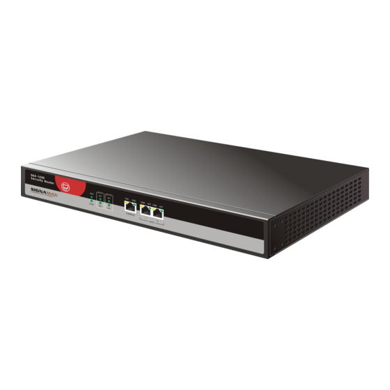
Page 6: 065-1530 Signamax Security Router Front Panel
RDY – inserting module link status CONSOLE (console port) TXD – sending console port data RXD – receiving console port data FETH1 (Ethernet interface1) 100M - 10/100M Ethernet interface data rate indicator On: 100M Off: 10M 4 SIGNAMAX LLC • www.signamax.eu... -
Page 7: 065-1530 Signamax Security Router Backboard Interface
- voice card module slot for VOP/VOS serial module SLOT0 - MIM module slot, which adopts modular design 065-1530 Signamax Security Router System The following table explains 065-1530 Signamax Security Router basic configuration and working environment: Item Description Console port One fixed, async DTE working mode (RJ45) 5 SIGNAMAX LLC •... -
Page 8: 065-1530 Signamax Security Router Functionality
Environment humidity Power supply rating power Maximum power consumption 065-1530 Signamax Security Router Functionality The following table explains 065-1530 Signamax Security Router functionality, and supported protocols and services. Protocols & services Description Network protocol WAN supports: PPP compression SLIP CSLIP protocol... - Page 9 Configure command-level protocol to guarantee unauthenticated user not to intrude into router: IP packet filter firewall IP UNNUMBERED IP policy routing DHCP relay PAP/CHAP validation EASY IP NAT network concealing RADIUS validation IPsec data encryption Load balance MPLS 7 SIGNAMAX LLC • www.signamax.eu...
-
Page 10: 065-1530 Signamax Security Router Main Board
The 065-1530 Signamax Security Router main board comprises three fixed interfaces, one voice card slot, one MIM slot, six indicators and power supply jack and one fixed interface. The 065-1530 Signamax Security Router provides three fixed interfaces – one console port, two... - Page 11 Supports auto-crossing Supported network protocol Slots: The 065-1530 Signamax Security Router has two slots - SLOT0 and SLOT1. SLOT0 comprises MIM slots, which can be inserted into different modules. SLOT0 supports the following modules: Ethernet interface module Sync/async interface module...
-
Page 12: Modules
Modules 065-1530 Signamax Security Router is a modular router. It provides two slots. SLOT1 is voice card slot for VOP and VOS serial voice module. SLOT0 is an MIM slot compatible with all interface modules of Signamax routers. Following are the modules:... -
Page 13: Sync/Async Serial Interface Module (Sae) Series
Sync/Async Serial Interface Module (SAE) Series 1-port High-speed V.24/V.35 Serial Module (1SAE) 1SAE module is used for 065-1530 Signamax Security Router. 1SAE completes 1-port sync/async serial data flow -- receiving and sending. The port operates in synchronous mode: DCE mode: 2.048Mbps... -
Page 14: Channelized E1 Module (Ce1)
1-port channelized E1 (1CE1) indicator: On: Cannot check frame sync signal Off: After sync 1CE1 Interface Connected Cable 1CE1 and BNC pin coaxial cable and RJ45-RJ45 connected twisted-pair. 1CE1 Interface Attributes 1-port Channelized E1 (1CE1) attributes: 12 SIGNAMAX LLC • www.signamax.eu... -
Page 15: Non-Channelized E1 (E1) Series
On: Non-transparent and cannot check frame sync signal Off: After sync 1E1 Interface Connected Cable 1E1 and BNC pin coaxial cable and RJ45-RJ45 connected twisted-pair. 1E1 Interface Attributes 1-port non-channelized E1 (1E1) attributes: Attributes Description 13 SIGNAMAX LLC • www.signamax.eu... -
Page 16: Frequency-Band Modem M336 Series
1-port 33.6K frequency-band MODEM (1M336) DIP: Mode Description DIP switch configuration Frequency-band LINE port used as inbuilt frequency-band MODEM mode MODEM interface Console port mode LINE port used as CONSOLE port. Configure router via dialup remote login 14 SIGNAMAX LLC • www.signamax.eu... -
Page 17: 1M336 Interface Module Connected Cable
1 M 12 8 M od ul e, I ndi c at or & DI P S wi t c h 1M128 interface module: 1-port 128K base-band MODEM (1M128): The 1-port 128K base-band MODEM (1M128) indicator: On: Link established 15 SIGNAMAX LLC • www.signamax.eu... -
Page 18: 1M128 Module Connected Cable
1-port ISDN U Module (1U) 1-port ISDN U module connects DDN network and ISDN network and not to connect modem. 1 U M od ul e & In d i ca t or 1U module: 16 SIGNAMAX LLC • www.signamax.eu... -
Page 19: 1 U M Od Ul E C Onn Ec T E D C A Bl E
1U module connected cable RJ45 (4, 5 signal cable) or RJ11 line. 1 U I n t er f a ce At tr i but es 1-port ISDN U module (1U) interface attributes: Attributes Description Tie-in RJ45 Interface number Supported link protocol Supported network protocol 17 SIGNAMAX LLC • www.signamax.eu... -
Page 20: Ip Module (Vop/Vos) Series
1 VO P I nt er f a ce At tr i b ut e s 1-port IP phone module (1VOP) interface attributes: Attributes Description Interface RJ45 jack Interface number H.225 Supported protocol H.245 RTCP G.711 G.723 G.729 18 SIGNAMAX LLC • www.signamax.eu... -
Page 21: 2-Port Ip Phone Module (2Vop)
2VOP module connected cable is RJ45 external cable. 2VOP Module Interface Attributes 2-port IP phone module (2VOP) interface attributes: Attributes Description Interface RJ45 jack (two RJ11 plugs) Interface 2 RJ11 number H.225 H.245 Supported RTCP protocol G.711 G.723 G.729 19 SIGNAMAX LLC • www.signamax.eu... -
Page 22: 1-Port Switch Ip Phone Module (1Vos)
1 VO S I nt er f a ce At tr i b ut e s 1-port switch IP phone module (1VOS) interface attributes: Attributes Description Interface RJ45 jack Interface number H.225 H.245 Supported RTCP protocol G.711 G.723 G.729 20 SIGNAMAX LLC • www.signamax.eu... -
Page 23: 2-Port Switch Ip Phone Module (2Vos)
2 VO S M o du l e Int er f a ce At tr i bu t e s 2-port switch IP phone module (2VOS) interface attributes: Attributes Description Interface RJ45 jack Interface number 2 (RJ11) Supported protocol H.225 H.245 RTCP G.711 G.723 G.729 21 SIGNAMAX LLC • www.signamax.eu... -
Page 24: Ethernet Module (Ete) Series
1 ET E M o dul e I nt er f ac e Att r i but es 1-port Ethernet port (1ETE) attributes: Attributes Description Tie-in RJ45 Tie-in number Supported protocol 802.3 ISDN S/T Module (ST) Series 1-port ISDN S/T Module (1ST) 1-port ISDN S/T module provides 64K or 128K high-speed access 22 SIGNAMAX LLC • www.signamax.eu... -
Page 25: 1St Module & Indicator
1ST cable is RJ45 connected Ethernet cable. 1 ST M o dul e I n ter f a ce Attri bu te s 1-port ISDN S/T module (1ST) interface attributes: Attributes Description Plug RJ45 Plug number Supported protocol 23 SIGNAMAX LLC • www.signamax.eu... -
Page 26: System Installation
System Installation Precautions Read this manual Place 065-1530 Signamax Security Router on flat surface to avoid falling down Do not put heavy material on 065-1530 Signamax Security Router Use UPS system Ensure proper grounding Do not open chassis with power supply... -
Page 27: Temperature & Humidity
0°C ~40°C 40%~65% 10%~90% Dust Prevention Dust is harmful for the operation of 065-1530 Signamax Security Router. Maintain a clean and dust-free atmosphere. Routers & Accessories Before installing router, check the router and accessories. Following is the 065-1530 Signamax Security Router basic configuration... -
Page 28: Machine Installation
Console port cable Ethernet cable (065-1530 Signamax Security Router Ethernet cable is configured according to the number of Ethernet modules) Modular interface cable Needed equipment: Ethernet 10 BASE-T HUB Configuring terminal (can be PC) Equipment relevant to optional module Machine Installation The dimensions of 065-1530 Signamax Security Router are 340mm x 230mm x 44mm (W×D×H). -
Page 29: Grounding Connection
The united grounding resistance should be < Good power supply grounding Main Control Board Cable Connection The section explains the method of connecting 065-1530 Signamax Security Router control board cable to network including connecting router console port. Console Port Connection The 065-1530 Signamax Security Router provides one EIA/TIA-232 async serial console port. - Page 30 Step 1: Find a character terminal. It can be standard terminal with RS- 232 serial or normal PC. Step 2: Ensure that power supply is off for router or terminal. Connect RS-232 serial and console port with cables. 28 SIGNAMAX LLC • www.signamax.eu...
-
Page 31: Grounding Wire Connection
Step 3: Push in the module close to back panel Step 4: Tighten the screw Rack/Desk If 065-1530 Signamax Security Router is placed onto 19-inch standard rack, use front-end installation method. If 065-1530 Signamax Security Router is placed on desk, stick the formula. -
Page 32: Hardware Installation
Step 6: Connect sync/async communication cable to router WAN interface. The 065-1530 Signamax Security Router sync/async interface works in the mode of V.24 or V.35. The two modes are completed via V.24/V.35 button. In V.24 mode, interface adopts standard RS232 cable connection. - Page 33 38400 64000 115200 V.35 cable rate and transmission distance: BR (bps) Max. transmission distance (m) 2400 1250 4800 9600 19200 38400 56000 64000 2048000 When adopting EIA/TIA-232 cable, BR rate should not be over 64Kbps. 31 SIGNAMAX LLC • www.signamax.eu...
-
Page 34: 1Sae Module Cable Connection
Step 1: Insert RJ11 plug of 1M336 module cable to LINE jack and other side with external wire. Step 2: After power on, check ACT status of 1M128 module. If the indicator is not on, check the circuit. 32 SIGNAMAX LLC • www.signamax.eu... -
Page 35: 1U Module Cable Connection
1ETE Module Cable Connection Connecting 1ETE module cable: Step 1: Insert RJ45 plug of 1ETE cable to RJ45 jack. Step 2: Connect another side of RJ45 plug to relevant equipment wire. 1ST Module Cable Connection 33 SIGNAMAX LLC • www.signamax.eu... - Page 36 Connecting 1ST module cable: Step 1: Insert RJ45 plug of 1ST module cable to RJ45 jack. Step 2: Connect another side of RJ45 plug to related equipment wire. 34 SIGNAMAX LLC • www.signamax.eu...
-
Page 37: Interface Cable Signals
Interface Cable Signals Ethernet Cable (Twisted-pair Interface RJ45) 065-1530 Signamax Security Router Ethernet interface cable is 8-core non-screen twisted-pair. Port1/2 is sending-end and port 3/6 is receiving-end. They are the same as Ethernet card interface, which can be connected to HUB. -
Page 38: Console Port Cable
Console Port Cable 065-1530 Signamax Security Router console port cable connects with PC 9-core serial jack. It is 8-core non-screen cable. One side is RJ45 plug and another side DB9 (hole). A-3 console port cable connection relation: RJ45 Signal Direction Length —>...
Need help?
Do you have a question about the 065-1530 and is the answer not in the manual?
Questions and answers