Table of Contents
Advertisement
Quick Links
Signamax™ Connectivity Systems
Signamax™ Connectivity Systems
Hardened Ethernet Switch
Hardened Ethernet Switch
U
U
S
S
E
E
Model -065-7405TB
Model -065-7405TB
065-7408ATB
065-7408ATB
065-74091FXSTTB
065-74091FXSTTB
065-74091FXSCTB
065-74091FXSCTB
'
'
R
R
S
S
1
Hardened Ethernet Switch
G
G
U
U
I
I
D
D
E
E
Advertisement
Table of Contents

Related Manuals for SignaMax 065-7405TB


Summary of Contents for SignaMax 065-7405TB
- Page 1 Hardened Ethernet Switch Signamax™ Connectivity Systems Signamax™ Connectivity Systems Hardened Ethernet Switch Hardened Ethernet Switch Model -065-7405TB Model -065-7405TB 065-7408ATB 065-7408ATB 065-74091FXSTTB 065-74091FXSTTB 065-74091FXSCTB 065-74091FXSCTB ’ ’...
-
Page 2: Quick Start Guide
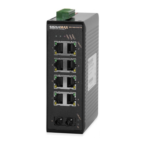
Hardened Ethernet Switch Quick Start Guide This quick start guide describes how to install and use the Signamax hardened Ethernet Switch. This is the switch of choice for harsh environments constrained by space. Physical Description The Terminal Block and Power inputs... -
Page 3: And 100Basefx Connectors
Hardened Ethernet Switch DC Terminal Block Power Inputs: There are two pairs of power inputs can be used to power up this Switch. Redundant power supplies function is supported. You only need to have one power input connected to run the Switch. 10/100BaseT/TX 100BaseFX Connectors... -
Page 4: The Port Status Leds
Hardened Ethernet Switch The Port Status LEDs... -
Page 5: Functional Description
Hardened Ethernet Switch Functional Description Meets NEMA TS1/TS2 Environmental requirements such as temperature, shock, and vibration for traffic control equipment. Meets IEC61000-6-2 EMC Generic Standard Immunity for industrial environment. UL1604 Class 1, Division 2 Classified for use in hazardous locations. Support 802.3/802.3u/802.3x. -
Page 6: Assembly, Startup, And Dismantling
Hardened Ethernet Switch State Indication POWER Switch is properly connected to power and Steady PWR1 turned on. PWR2 Switch is not connected to power and is (Green) turned off. FAULT 1. Power failure occurred. Steady 2. Port failure occurred (when port fault alarm dip switch is enabled). - Page 7 Hardened Ethernet Switch...
-
Page 8: Preface
Hardened Ethernet Switch Preface A member of the growing Signamax family of harsh environment switches, this switch addresses a need for a smaller switch. This switch provides an affordable solution for rugged and outdoor environment, transportation road-side cabinet, industrial floor shop, multitenant dwellings or Fiber To The Home (FTTH) applications. -
Page 9: Table Of Contents
Hardened Ethernet Switch Table of Contents QUICK START GUIDE ..............2 .............. 2 HYSICAL ESCRIPTION The Terminal Block and Power inputs......2 10/100BaseT/TX 100BaseFX Connectors ..3 The Port Status LEDs ............4 ............5 UNCTIONAL ESCRIPTION ........6 SSEMBLY TARTUP ISMANTLING PREFACE.................. -
Page 10: Product Overview
Hardened Ethernet Switch Product Overview Hardened Ethernet Switch... -
Page 11: Package Contents
Hardened Ethernet Switch Package Contents When you unpack the product package, you shall find the items listed below. Please inspect the contents, and report any apparent damage or missing items immediately to your authorized reseller. This Switch User’s Manual External power adapter & Power Cord (Optional) Product Highlights Basic Features... -
Page 12: Front Panel Display
Hardened Ethernet Switch Supports DIN-Rail or Panel Mounting installation. Front Panel Display... -
Page 13: Physical Ports
Hardened Ethernet Switch Status LEDs State Indication POWER Steady Switch is properly connected to power and turned on. PWR1 PWR2 Switch is not connected to power and is turned off. (Green) FAULT 3. Power failure occurred. Steady 4. Port failure occurred (when port fault alarm dip switch is enabled). -
Page 14: Installation
Hardened Ethernet Switch Installation This chapter gives step-by-step instructions about how to install the switch: Selecting a Site for the Switch As with any electric device, you should place the switch where it will not be subjected to extreme temperatures, humidity, or electromagnetic interference. -
Page 15: Din Rail Mounting
Hardened Ethernet Switch DIN Rail Mounting Fix the DIN rail attachment plate to the back panel of the switch. Installation: Place the switch on the DIN rail from above using the slot. Push the front of the switch toward the mounting surface until it audibly snaps into place. -
Page 16: Connecting To Power
Hardened Ethernet Switch Connecting to Power Redundant DC Terminal Block Power Inputs There are two pairs of power inputs can be used to power up this device. You only need to have one power input connected to run the switch. Step 1: Connect the DC power cord to the plug-able terminal block on the switch, and then plug it into a standard DC outlet. -
Page 17: Alarms For Power And Port Failure
Hardened Ethernet Switch Alarms for Power and Port Failure Step 1: There are two pins on the terminal block are used for power failure detection. It provides the normally closed output when the power source is active. Use this as a dry contact application to send a signal for power failure detection. -
Page 18: Connecting To Your Network
Hardened Ethernet Switch Connecting to Your Network Cable Type & Length It is necessary to follow the cable specifications below when connecting the switch to your network. Use appropriate cables that meet your speed and cabling requirements. Cable pecifications Speed Connector Port Speed Cable... -
Page 19: Cabling
Hardened Ethernet Switch Cabling Step 1: First, ensure the power of the switch and end devices are turned off. Always ensure that the power is off before any installation. <Note> Step 2: Prepare cable with corresponding connectors for each type of port in use. -
Page 20: Specifications
Hardened Ethernet Switch Specifications 10/100BaseT/TX auto-negotiating ports with Hardened Ethernet RJ-45 connectors, 100BaseFX fiber ports Switch Applicable IEEE 802.3 10BaseT IEEE 802.3u 100BaseTX/FX Standards Store-and-Forward Switching Method Forwarding Rate 10BaseT: 10 / 20Mbps half / full-duplex 100BaseTX/FX: 100 / 200Mbps half / full-duplex 14,880pps for 10Mbps Performance 148,810pps for 100Mbps... - Page 21 Hardened Ethernet Switch EN61000-6-2: EN61000-4-2 (ESD Standards) EN61000-4-3 (Radiated RFI Standards) EN61000-4-4 (Burst Standards) EN61000-4-5 (Surge Standards) EN61000-4-6 (Induced RFI Standards) EN61000-4-8 (Magnetic Field Standards) EN61000-4-11 (Voltage Dip Standards) Environmental Test Compliance IEC60068-2-6 Fc (Vibration Resistance) IEC60068-2-27 Ea (Shock) IEC60068-2-32 Ed (Free Fall) NEMA TS1/2 Environmental requirements for traffic control equipment...
-
Page 22: Appendix A - Connector Pinouts
Hardened Ethernet Switch Appendix A – Connector Pinouts Pin arrangement of RJ-45 connectors: RJ-45 Connector and Cable Pins The following table lists the pinout of 10/100BaseT/TX ports. Regular Ports Uplink port Input Receive Data + Output Transmit Data + Input Receive Data - Output Transmit Data - Output Transmit Data + Input Receive Data +... -
Page 23: Contact Information
Hardened Ethernet Switch Contact Information SIGNAMAX™ CONNECTIVITY SYSTEMS An AESP Company 1810 N.E. 144th Street. North Miami, Florida 33181, U.S.A. Phone: 305-944-7710 Fax: 305-652-8489 Sales: 800-446-2377 Tech. Support: 800-446-2377, ext. 201 Http://www.signamax.com E-mail: info@signamax.com...
Need help?
Do you have a question about the 065-7405TB and is the answer not in the manual?
Questions and answers