
Related Manuals for SignaMax 065-7734


Summary of Contents for SignaMax 065-7734
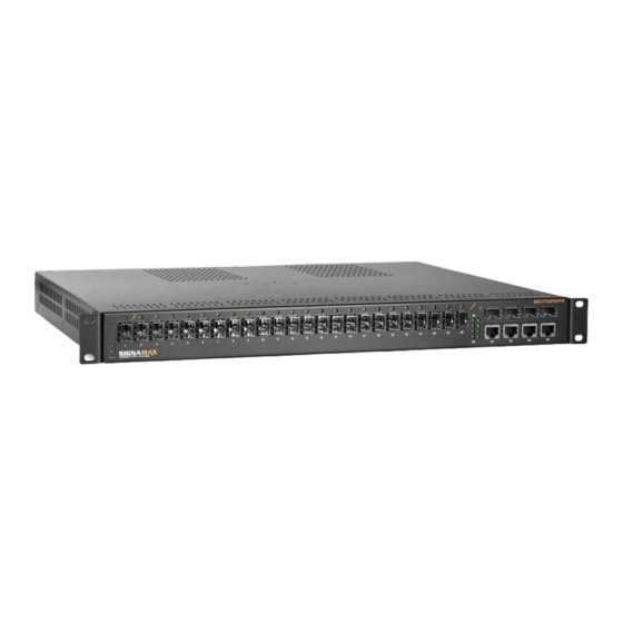
- Page 1 Signamax Connectivity Systems Managed Ethernet Switch Model -065-7734 ’...
-
Page 2: Quick Start Guide
Managed Ethernet Switch Quick Start Guide This quick start guide describes how to install and use the Managed Ethernet Switch. Physical Description The Port Status LEDs and Power Inputs State Indication Steady Power on Power 1, 2 Power off 10/100BaseTX, 100BaseFX/BX, SFP Steady A valid network connection established Link/ACT... -
Page 3: Functional Description
Managed Ethernet Switch Functional Description RS-232 console, Telnet, SNMP v1 & v2c & v3, RMON, Web Browser, and TFTP management. Supports Command Line Interface in RS-232 console. Supports 8192 MAC addresses. Provides 3M bits memory buffer. Supports IEEE802.3/802.3u/802.3ab/802.3z/802.3x. -
Page 4: Console Configuration
Managed Ethernet Switch Console Configuration Connect to the switch console: Connect the DB9 straight cable to the RS-232 serial port of the device and the RS-232 serial port of the terminal or computer running the terminal emulation application. Direct access to the administration console is achieved by directly connecting a terminal or a PC equipped with a terminal-emulation program (such as HyperTerminal) to the switch console port. - Page 5 Managed Ethernet Switch Logon to Privileged Exec Mode (Enable Mode): At the “switch_a>” prompt just type in “enable” and press <Enter> to logon to Privileged Exec Mode (or Enable Mode). And the “switch_a#” prompt will show on the screen. ...
-
Page 6: Web Configuration
Managed Ethernet Switch Web Configuration Login the switch: Specify the default IP address (192.168.1.10) of the switch in the web browser. A login window will be shown as below: User’s Manual... - Page 7 Managed Ethernet Switch Enter the factory default login ID: root. Enter the factory default password (no password). Then click on the “Login” button to log on to the switch. User’s Manual...
-
Page 8: Preface
Managed Ethernet Switch Preface This manual describes how to install and use the Signamax Managed Ethernet Switch. This switch introduced here is designed to deliver full scalability with SNMP/RMON web-based management functions by providing: To get the most out of this manual, you should have an understanding of Ethernet networking concepts. -
Page 9: Table Of Contents
Managed Ethernet Switch Table of Contents Quick Start Guide HYSICAL ESCRIPTION The Port Status LEDs and Power Inputs UNCTIONAL ESCRIPTION ONSOLE ONFIGURATION ONFIGURATION Preface Table of Contents Product Overview ANAGED THERNET WITCH ACKAGE ONTENTS RODUCT IGHLIGHTS Basic Features Management Support RONT ANEL ISPLAY... - Page 10 Managed Ethernet Switch VERVIEW SNMP A MIB-2 (RFC 1213) GENT AND RMON MIB (RFC 2819) MIB (RFC 1493) RIDGE RMON Groups Supported Bridge Groups Supported Web-Based Browser Management OGGING ON TO THE SWITCH NDERSTANDING THE ROWSER NTERFACE YSTEM WITCHING RUNKING STP / R VLAN SNMP...
-
Page 11: Product Overview
Managed Ethernet Switch Product Overview Managed Ethernet Switch Front View Package Contents When you unpack the product package, you shall find the items listed below. Please inspect the contents, and report any apparent damage or missing items immediately to your authorized reseller. -
Page 12: Product Highlights
Managed Ethernet Switch Product Highlights Basic Features RS-232 console, Telnet, SNMP v1 & v2c & v3, RMON, Web Browser, and TFTP management. Supports Command Line Interface in RS-232 console. Supports 8192 MAC addresses. Provides 3M bits memory buffer. ... - Page 13 Managed Ethernet Switch PORT-MIRRORING Port-mirroring QOS (IEEE802.1p Quality of Service) 4 priority queues INTERNETWORKING PROTOCOLS Bridging: IEEE802.1s Multiple Spanning Tree IEEE802.1w Rapid Spanning Tree IEEE802.1D Spanning Tree compatible IEEE802.1Q – GVRP Ring IP Multicast: IGMP Snooping ...
-
Page 14: Front Panel Display
Managed Ethernet Switch Front Panel Display POWER This LED comes on when the switch is properly connected to power and turned on. P ort S ta tus LEDs The LEDs are located on the front panel, displaying status for each respective port. - Page 15 Managed Ethernet Switch CONNECTIVITY RJ-45 connectors on TX ports Duplex LC connector on SFP 100BaseFX/BX fiber transceivers Duplex LC connector on SFP 1000BaseSX/LX/BX fiber transceivers MODE SELECTION 10BaseT full-duplex mode 10BaseT half-duplex mode 100BaseTX full-duplex mode ...
-
Page 16: Switch Management
Managed Ethernet Switch Switch Management Web-based browser interface The switch also boasts a point-and-click browser-based interface that lets user access full switch configuration and functionality from a Netscape or Internet Explorer browser. Administration console via RS-232 serial port (CLI) The switch provides an onboard serial port, which allows the switch to be configured via a directly connected terminal. -
Page 17: Installation
Managed Ethernet Switch Installation This chapter gives step-by-step instructions about how to install the switch: Selecting a Site for the Switch As with any electric device, you should place the switch where it will not be subjected to extreme temperatures, humidity, or electromagnetic interference. -
Page 18: Connecting To Your Network
Managed Ethernet Switch Connecting to Your Network Cable Type & Length It is necessary to follow the cable specifications below when connecting the switch to your network. Use appropriate cables that meet your speed and cabling requirements. Cable Specifications Speed Connector Port Cable... -
Page 19: Cabling
Managed Ethernet Switch Cabling Step 1: First, ensure the power of the switch and end devices are turned off. <Note> Always ensure that the power is off before any installation. Step 2: Prepare cable with corresponding connectors for each type of port in use. -
Page 20: Switch Management
Managed Ethernet Switch Switch Management This chapter explains the methods that you can use to configure management access to the switch. It describes the types of management applications and the communication and management protocols that deliver data between your management device (workstation or personal computer) and the system. -
Page 21: Administration Console (Cli)
Managed Ethernet Switch Administration Console (CLI) The administration console is an internal, character-oriented, Command Line Interface (CLI) for performing system administration such as displaying statistics or changing option settings. Using this method, you can view the administration console from a terminal, personal computer, Apple Macintosh, or workstation connected to the switch’s console port. -
Page 22: Modem Access
Managed Ethernet Switch the terminal serial port. A workstation attachment under UNIX can use an emulator such as TIP. Modem Access You can access the switch’s administration console from a PC or Macintosh using an external modem attached to the console port. The switch management program provides Console Port screen, accessible from the Basic Management screen that lets you configure parameters for modem access. -
Page 23: Protocols
Managed Ethernet Switch the MIBs. However, if it only knows the get community string, it can only read MIBs. The default get and set community strings for the switch are public. Protocols The switch supports the following protocols: VIRTUAL TERMINAL PROTOCOLS, SUCH AS TELNET A virtual terminal protocol is a software program, such as Telnet, that allows you to establish a management session from a Macintosh, a PC, or a UNIX workstation. -
Page 24: Web-Based Browser Management
Managed Ethernet Switch Web-Based Browser Management The switch provides a web-based browser interface for configuring and managing the switch. This interface allows you to access the switch using a preferred web browser. This chapter describes how to configure the switch using its web-based browser interface. -
Page 25: Snmp & Rmon Management
Managed Ethernet Switch SNMP & RMON Management This chapter describes the switch’s Simple Network Management Protocol (SNMP) and Remote Monitoring (RMON) capabilities. Overview RMON is an abbreviation for the Remote Monitoring MIB (Management Information Base). RMON is a system defined by the Internet Engineering Task Force (IETF) document RFC 2819, which defines how networks can be monitored remotely. -
Page 26: Snmp Agent And Mib-2 (Rfc 1213)
Managed Ethernet Switch SNMP Agent and MIB-2 (RFC 1213) The SNMP Agent running on the switch manager CPU is responsible for: - Retrieving MIB counters from various layers of software modules according to the SNMP GET/GET NEXT frame messages. - Setting MIB variables according to the SNMP SET frame message. - Generating an SNMP TRAP frame message to the Network Management Station if the threshold of a certain MIB counter is reached or if other trap conditions (such as the following) are met:... -
Page 27: Rmon Groups Supported
Managed Ethernet Switch RMON Groups Supported The switch supports the following RMON MIB groups defined in RFC 2819: - RMON Statistics Group – maintains utilization and error statistics for the switch port being monitored. - RMON History Group – gathers and stores periodic statistical samples from the previous Statistics Group. -
Page 28: Web-Based Browser Management
Managed Ethernet Switch Web-Based Browser Management The switch provides a web-based browser interface for configuring and managing the switch. This interface allows you to access the switch using a preferred web browser. This chapter describes how to configure the switch using its web-based browser interface. - Page 29 Managed Ethernet Switch changed the factory default password. Then click on the “Login” button to log on to the switch. User’s Manual...
-
Page 30: Understanding The Browser Interface
Managed Ethernet Switch Understanding the Browser Interface The web browser interface provides groups of point-and-click buttons at the left field of the screen for configuring and managing the switch. SYSTEM System Information, System Name/Password, IP Address, ARP Table, Route Table, Save Configuration, Firmware Upgrade, Reboot, Logout PORT Configuration, Port Status, Rate Control, RMON Statistics, Per Port Vlan Activities... - Page 31 Managed Ethernet Switch VLAN VLAN Mode Setting, 802.1Q VLAN Setting, 802.1Q Port Setting, Port Based VLAN Global Configuration, 802.1p Priority, DSCP SNMP SNMP General Setting, SNMP v1/v2c, SNMP v3 802.1X Radius Configuration, Port Authentication OTHER PROTOCOLS GVRP, IGMP Snooping, NTP User’s Manual...
-
Page 32: System
Managed Ethernet Switch System System Information The System name, Firmware version, System time, MAC address, Default gateway, DNS Server, VLAN ID, IP Address, and IP Subnet Mask of Switch. User’s Manual... - Page 33 Managed Ethernet Switch System Name/Password System Name: Click in “System Name” text box. Type a system name if it is blank, or replace the current system name with a new one. Updating setting: Click “Updating setting” button to update your settings. Password: Click in “Password”...
- Page 34 Managed Ethernet Switch IP Address IP Address: Click in “IP Address” text box and type a new address to change the IP Address. IP Subnet Mask: Click in “IP Subnet Mask” text box and type a new address to change the IP Subnet Mask. Submit: Click “Submit”...
- Page 35 Managed Ethernet Switch ARP Table Click ARP Table to view ARP Table. User’s Manual...
- Page 36 Managed Ethernet Switch Route Table Click Route Table to view Route Table. Save Configuration Load config from TFTP server: Click in “TFTP Server” text box and type the TFTP server IP address from where the file will be obtained. Click in “FILE” text box and type the name of the file that will be obtained.
- Page 37 Managed Ethernet Switch configuration. Firmware Upgrade Filename: Click in “Filename” text box and type the name of the file that you intend to upgrade it to the switch. TFTP server IP: Click in “TFTP server IP” text box and type the TFTP server IP address from where the file will be obtained.
- Page 38 Managed Ethernet Switch Please follow the message on the screen during the firmware upgrade process. Do not turn off the power or perform other functions during this period of time. User’s Manual...
- Page 39 Managed Ethernet Switch Firmware has been upgraded successfully to the switch. Reboot the switch after completing the upgrade process. User’s Manual...
- Page 40 Managed Ethernet Switch Reboot Reboot: Click “Reboot” button to restart the switch. User’s Manual...
- Page 41 Managed Ethernet Switch Logout Logout: Click “Logout” button to logout of the switch. User’s Manual...
-
Page 42: Port
Managed Ethernet Switch Port Configuration Admin Setting: Click “Admin Setting” drop-down menu to choose “Link down” or “Link up” from the “Admin Setting” drop-down list to disable or enable Admin Setting for the port. Speed: Click “Speed” drop-down menu to change the line speed and duplex settings from the “Speed”... - Page 43 Managed Ethernet Switch Port Status View the Link Status, Speed, Duplex, and Flow control status for all ports. User’s Manual...
- Page 44 Managed Ethernet Switch Rate Control Ingress: Click in “Ingress” text box and type a new Rate to change the Ingress Rate Control for the port. The rate value is a multiple of 62.5kbps. Please round off decimal fraction of rate value and only key the integer of rate value in “Ingress” text box.
- Page 45 Managed Ethernet Switch 875kbps, 937kbps, 1000kbps, … , 1000000kbps. Update setting: Click “Update setting” button when you finished these Rate Control settings. RMON Statistics Click Port 1 ~ Port 28 to view corresponding RMON Statistics. User’s Manual...
- Page 46 Managed Ethernet Switch Per Port Vlan Activities Click Port 1 ~ Port 28 to view corresponding vlan activities. User’s Manual...
-
Page 47: Switching
Managed Ethernet Switch Switching Bridging Aging Time (seconds): Click the text box and type a decimal number as Bridging Aging Time in seconds. Update setting: Click “update setting” button when you finished Aging Time settings. Threshold level (0.1-100): Click in “Level” text box and type a decimal number port. - Page 48 Managed Ethernet Switch Update Setting: Click “Update Setting” button when you finished Threshold level and Storm-control enabled type settings. User’s Manual...
- Page 49 Managed Ethernet Switch Static MAC Entry Static-MAC-Entry Forward: Add MAC address: Click in “Add MAC address” text box and type a locked forwarding MAC address for the port. VLAN ID: Click “VLAN ID” drop-down menu and choose a VLAN ID from the “VLAN ID”...
- Page 50 Managed Ethernet Switch Port Mirroring Mirror From: Choose Mirror From port from Port 1 ~ Port 28. Mirror To: Click “Mirror To” drop-down menu to Choose Mirror To port (Port 1 ~ Port 28) from “Mirror To” drop-down list. Mirror Mode: Click “Mirror Mode” drop-down menu to Choose “Tx/Rx”, “Tx”, or “Rx”...
-
Page 51: Trunking
Managed Ethernet Switch Trunking Port Trunking Static Channel Group: Trunk 1 ~ 6: Click Port 1 ~ Port 24 to assign ports to Trunk 1 ~ 6. (Maximum 8 ports per Trunk.) Submit: Click “Submit” button when you finished Static Channel Group settings. -
Page 52: Stp / Ring
Managed Ethernet Switch STP / Ring Global Configuration Spanning Tree Protocol: Click “Spanning Tree Protocol” drop-down menu to Choose “Enable” or “Disable” from “Spanning Tree Protocol” drop-down list to enable or disable Spanning Tree Protocol. Bridge Priority (0..61440): Click in “Bridge Priority” text box and type a decimal number between 0 and 61440. - Page 53 Managed Ethernet Switch User’s Manual...
- Page 54 Managed Ethernet Switch RSTP Port Setting STP Version: Click “STP Version” drop-down menu to choose “RSTP” from “STP Version” drop-down list. Port: Click “Port” drop-down menu to choose Port 1 ~ Port 28 from “Port” drop-down list. Priority(Granularity 16): Click in “Priority” text box and enter a value between 0 and 240 to set the priority for the port.
- Page 55 Managed Ethernet Switch MSTP Properties STP Version: Click “STP Version” drop-down menu to choose “MSTP” from “STP Version” drop-down list. User’s Manual...
- Page 56 Managed Ethernet Switch Region Name: Click in “Region Name” text box to create an MST region and specify a name to it. MST bridges of a region form different spanning trees for different VLANs. By default, each MST bridge starts with the region name as its bridge address.
- Page 57 Managed Ethernet Switch MSTP Instance Setting VLAN Instance Configuration VLAN Instance Configuration: Click “VLAN Instance Configuration” button. The “VLAN Instance Configuration” window appears. VLAN ID: Click “VLAN ID” drop-down menu to choose VLAN from “VLAN ID” drop-down list to simultaneously add multiple VLANs for the corresponding instance of a bridge.
- Page 58 Managed Ethernet Switch User’s Manual...
- Page 59 Managed Ethernet Switch User’s Manual...
- Page 60 Managed Ethernet Switch MSTP Port Setting Port Instance Configuration Instance ID: Click “Instance ID” drop-down menu to choose instance ID from “Instance ID” drop-down list. Click Port 1 ~ Port 28 to assign ports to the corresponding instance ID. Update setting: Click “Update setting” button when you finished Port Instance Configuration.
- Page 61 Managed Ethernet Switch Ring Setting Ring state Click “Ring state” drop-down menu from “Ring state” drop-down list to choose “Enable” or “Disable” to enable or disable Ring state. Update setting: Click “Update setting” button when you finished Ring state setting. Set ring port Ring port 1: Click “Ring port 1”...
-
Page 62: Vlan
Managed Ethernet Switch VLAN VLAN Mode Setting VLAN Mode Setting: Click “VLAN Mode Setting” drop-down menu to Choose “Tag-based VLAN” or “Port-based VLAN” from “VLAN Mode Setting” drop-down list. Update Setting: Click “Update Setting” button when you finished VLAN Mode Setting. User’s Manual... - Page 63 Managed Ethernet Switch User’s Manual...
- Page 64 Managed Ethernet Switch 802.1Q VLAN setting Add VLAN: VLAN setting: Click “VLAN setting”. The “VLAN Setting” window appears. Add VLAN: Click “Add VLAN” button to create a new VLAN from “VLAN Setting” window. VLAN ID(2-4094): Click in the “VLAN ID” textbox and specify a new VLAN ID number from 2 ~ 4094.
- Page 65 Managed Ethernet Switch Delete VLAN: VLAN setting: Click “VLAN setting”. The “VLAN Setting” window appears. Delete VLAN: Click “Delete VLAN” button. Select a VLAN ID: Click “Select a VLAN ID” drop-down menu from “Select a VLAN ID” drop-down list to choose the VLAN to be deleted. Submit: Click “Submit”...
- Page 66 Managed Ethernet Switch VLAN Port Setting VLAN Port Setting: Click “VLAN Port Setting”. The “VLAN Port Setting” window appears. Mode: Click “Mode” drop-down menu to Choose “Access”, “Trunk”, or “Hybrid” from “Mode” drop-down list for the port. The port will be Tag port if you choose “Trunk”...
- Page 67 Managed Ethernet Switch Port Based VLAN VLAN: Choose the port to be added to or deleted from the VLAN. Select all: Click “select all” button to choose Port 1 ~ Port 28 all to be User’s Manual...
- Page 68 Managed Ethernet Switch added to the VLAN. Delete all: Click “delete all” button to choose Port 1 ~ Port 28 all to be deleted from the VLAN. Submit: Click “Submit” button when you finished Port Based VLAN setting. User’s Manual...
-
Page 69: Qos
Managed Ethernet Switch Global Configuration QoS: Click “QoS” drop-down menu from “QoS” drop-down list to choose “Enable” or “Disable” to enable or disable QoS. Trust: Enable or disable the switch port to trust the CoS (Class of Service) labels of all traffic received on that port. Enable or disable a routed port to trust the DSCP (Differentiated Service Code Point) labels of all traffic received on that port. - Page 70 Managed Ethernet Switch 802.1p Priority Priority: Click “Priority” drop-down menu from “Priority” drop-down list to choose 0 ~ 3 for VLAN Priority 0 ~ 7. Submit: Click “Submit” button when you finished 802.1p priority. User’s Manual...
- Page 71 Managed Ethernet Switch DSCP Priority: Click “Priority” drop-down menu from “Priority” drop-down list to choose 0 ~ 3 for DSCP Priority 0 ~ 63. Submit: Click “Submit” button when you finished DSCP. User’s Manual...
-
Page 72: Snmp
Managed Ethernet Switch SNMP SNMP General Setting SNMP Status: Click “SNMP Status” drop-down menu from “SNMP Status” drop-down list to choose “Enable” or “Disable” to enable or disable SNMP. Description: Click in the “Description” textbox and specify a new description for SNMP. Location: Click in the “Location”... - Page 73 Managed Ethernet Switch Warm Start Trap: Click “Warm Start Trap” drop-down menu from “Warm Start Trap” drop-down list to choose “Enable” or “Disable” to enable or disable warm start trap. Link Down Trap: Click “Link Down Trap” drop-down menu from “Link Down Trap”...
- Page 74 Managed Ethernet Switch SNMP v3 Add User: Add User: Click “Add User” button. The “SNMP V3 Setting” window appears. SNMP Version: Click “SNMP Version” drop-down menu from “SNMP Version” drop-down list to choose “SNMPv3 No-Auth”, “SNMPv3 Auth-MD5”, “SNMPv3 Auth-SHA”, “SNMPv3 Priv Auth-MD5”, or “SNMPv3 Priv Auth-SHA”.
- Page 75 Managed Ethernet Switch password. SNMPv3 Auth-SHA: Add a user using SNMP v3 with authentication. Click in the “Auth. Password” textbox and specify an authentication password. SNMPv3 Priv Auth-MD5: Add a user using SNMP v3 with authentication and privacy. Click in the “Auth. Password” textbox and specify authentication password.
- Page 76 Managed Ethernet Switch 802.1x Radius Configuration Radius Status: Click “Radius Status” drop-down menu from “Radius Status” drop-down list to choose “Enable” or “Disable” to globally enable or disable authentication. Update Setting: Click “Update Setting” button when you finished Radius Status Setting. User’s Manual...
- Page 77 Managed Ethernet Switch Add Radius: Add Radius: Click “Add Radius” button. The “Radius Server Setting” window appears. Radius Server IP: Click in the “Radius Server IP” textbox and specify the IP address of the remote radius server host. Radius Server Port: Click in the “Radius Server Port” textbox and specify the UDP destination port for authentication requests.
- Page 78 Managed Ethernet Switch Port-Based Authentication Interface: Click “Interface” drop-down menu from “Interface” drop-down list to choose the port to be set port-based authentication. Authentication State: Click “Authentication State” drop-down menu from “Authentication State” drop-down list to choose “Enable” or “Disable” to enable or disable authentication state.
- Page 79 Managed Ethernet Switch reauthorization attempts. The default time is 3600 seconds. Update Setting: Click “Update Setting” button when you finished port-based authentication setting. User’s Manual...
-
Page 80: Other Protocols
Managed Ethernet Switch Other Protocols GVRP GVRP Global Setting: GVRP: Click “GVRP” drop-down menu from “GVRP” drop-down list to choose “Enable” or “Disable” to enable or disable GVRP (GARP VLAN Registration Protocol). Dynamic VLAN creation: Click “Dynamic VLAN creation” drop-down menu from “Dynamic VLAN creation”... - Page 81 Managed Ethernet Switch Update Setting: Click “Update Setting” button when you finished GVRP Global Setting. Per port setting (include LAG): GVRP: Click “GVRP” drop-down menu from “GVRP” drop-down list to choose “Enable” or “Disable” to enable or disable GVRP for the port. GVRP applicant: Click “GVRP applicant”...
- Page 82 Managed Ethernet Switch Update Setting: Click “Update Setting” button when you finished IGMP mode settings. VLAN ID: Click “VLAN ID” drop-down menu from “VLAN ID” drop-down list to choose the VLAN under configuration for the switch. IGMP version: Click “IGMP version” drop-down menu from “IGMP version”...
- Page 83 Managed Ethernet Switch NTP Setting: NTP Status: Click “NTP Status” drop-down menu from “NTP Status” drop-down list to choose “Enable” or “Disable” to enable or disable NTP for the Switch. NTP Server (IP Address or Domain name): Click in the “NTP Server” textbox and specify the IP address or Domain name of NTP server.
- Page 84 Managed Ethernet Switch "Weekday", or "Date" to choose disable, weekday, or date daylight saving for the Switch. Time Set Offset (1-1440 min): Click in the "Time Set Offset" textbox and specify the offset time of daylight saving. For example enter 60 for one hour offset.
-
Page 85: Command Line Console Management
Managed Ethernet Switch Command Line Console Management The switch provides a command line console interface for configuration purposes. The switch can be configured either locally through its RS-232 port or remotely via a Telnet session. For the later, you must specify an IP address for the switch first. -
Page 86: Exec Mode (View Mode)
Managed Ethernet Switch Exec Mode (View Mode) Logon to Exec Mode (View Mode) At the switch_a login: prompt just type in “root” and press <Enter> to logon to Exec Mode (or View Mode). switch_a login: root User’s Manual... - Page 87 Managed Ethernet Switch Basic commands Exec Mode (or View Mode) is the base mode from where users can perform basic commands like: clear, debug, disable, enable, exit, help, logout, no, quit, show, terminal The CLI contains a text-based help facility. Access this help by typing in the full or partial command string then typing a question mark “?”.
- Page 88 Managed Ethernet Switch Login timed out The login session to Exec Mode (or View Mode) has timed out due to an extended period of inactivity (60 seconds) to indicate authentication attempt timed out. And the switch_a login: prompt will show on the screen. Logon back to Exec Mode (View Mode) User’s Manual...
- Page 89 Managed Ethernet Switch At the switch_a login: prompt just type in “root” and press <Enter> to logon back to Exec Mode (or View Mode). switch_a login: root Exit from Exec Mode (View Mode) At the switch_a> prompt just type in “exit” and press <Enter> to exit from Exec Mode (or View Mode).
-
Page 90: Privileged Exec Mode (Enable Mode)
Managed Ethernet Switch Privileged Exec Mode (Enable Mode) Logon to Privileged Exec Mode (Enable Mode) At the switch_a> prompt just type in “enable” and press <Enter> to logon to Privileged Exec Mode (or Enable Mode). And the switch_a# prompt will show on the screen. - Page 91 Managed Ethernet Switch Commands Privileged Exec Mode (or Enable Mode) allows users to run commands as following. At the switch_a# prompt just press <?> to list the commands. switch_a#? User’s Manual...
- Page 92 Managed Ethernet Switch At the switch_a# prompt just type in the full or partial command string then typing a question mark “?” to display the command keywords or parameters along with a short description. switch_a#show ? User’s Manual...
- Page 93 Managed Ethernet Switch Login timed out The login session to Privileged Exec Mode (or Enable Mode) has timed out due to an extended period of inactivity (60 seconds) to indicate authentication attempt timed out. And the switch_a login: prompt will show on the screen. Logon back to Exec Mode (View Mode) At the switch_a login: prompt just type in “root”...
- Page 94 Managed Ethernet Switch Exit from Privileged Exec Mode (or Enable Mode) At the switch_a# prompt just type in “exit” and press <Enter> to exit from Privileged Exec Mode (or Enable Mode). switch_a#exit User’s Manual...
-
Page 95: Configure Mode (Configure Terminal Mode)
Managed Ethernet Switch Configure Mode (Configure Terminal Mode) Logon to Configure Mode (Configure Terminal Mode) At the switch_a# prompt just type in “configure terminal” and press <Enter> to logon to Configure Mode (or Configure Terminal Mode). And the switch_a(config)# prompt will show on the screen. switch_a#configure terminal Commands Configure Mode (or Configure Terminal Mode) serves as a gateway into the... - Page 96 Managed Ethernet Switch At the switch_a(config)# prompt just type in the full or partial command string then typing a question mark “?” to display the command keywords or parameters along with a short description. switch_a(config)#show ? User’s Manual...
- Page 97 Managed Ethernet Switch Login timed out The login session to Configure Mode (or Configure Terminal Mode) has timed out due to an extended period of inactivity (60 seconds) to indicate authentication attempt timed out. And the switch_a login: prompt will show on the screen.
- Page 98 Managed Ethernet Switch Exit from Configure Mode (or Configure Terminal Mode) At the switch_a(config)# prompt just type in “exit” and press <Enter> to exit from Configure Mode (or Configure Terminal Mode). switch_a(config)#exit User’s Manual...
-
Page 99: System
Managed Ethernet Switch System System Information, System Name/Password, IP Address, ARP Table, Route Table, Save Configuration, Firmware Upgrade, Reboot, Logout System Name/Password System Name: Command Mode: Configure mode Logon to Configure Mode (Configure Terminal Mode). The switch_a(config)# prompt will show on the screen. switch_a(config)# Usage: Use hostname command to set or change the network server name. - Page 100 Managed Ethernet Switch switch_a(config)# IP Address IP Address/IP Subnet Mask: Command Mode: Interface mode Logon to Configure Mode (Configure Terminal Mode). Then logon to Interface mode. vlan1.1 means vlan 1. The switch_a(config-if)# prompt will show on the screen. switch_a(config)#interface vlan1.1 switch_a(config-if)# Usage: Use ip address command to set the IP address of an interface.
- Page 101 Managed Ethernet Switch Command Syntax: ip default-gateway IP-ADDRESS no ip default-gateway IP-ADDRESS A.B.C.D specifies the IP address of the default gateway. Example: The following example sets the default gateway 192.168.1.254 to switch: switch_a(config)#ip default-gateway 192.168.1.254 switch_a(config)# DNS Server: Command Mode: Configure mode Logon to Configure Mode (Configure Terminal Mode).
- Page 102 Managed Ethernet Switch The following example shows the ARP Table of switch: switch_a#show arp-table Route Table Command Mode: Privileged Exec mode Logon to Privileged Exec Mode (Enable Mode). The switch_a# prompt will show on the screen. switch_a(config)# Usage: Use show route-table command to view Route Table. Command Syntax: show route-table Example:...
- Page 103 Managed Ethernet Switch Command Mode: Privileged Exec mode Logon to Privileged Exec Mode (Enable Mode). The switch_a# prompt will show on the screen. switch_a# Usage: Use write config-file command to backup configuration file to tftp server. Command Syntax: write config-file IP-ADDRESS IP-ADDRESS specifies the IP address of tftp server.
- Page 104 Managed Ethernet Switch Usage: Use restore default command to restore default setting of the switch. Command Syntax: restore default Example: The following example restores default setting of the switch: switch_a#restore default switch_a# Auto Save: Command Mode: Configure mode Logon to Configure Mode (Configure Terminal Mode). The switch_a(config)# prompt will show on the screen.
- Page 105 Managed Ethernet Switch Command Syntax: service auto-config interval WORD WORD specifies the interval value. Example: The following example sets the interval WORD (10) when the configuration would be automatically saved to switch: switch_a(config)#service auto-config interval 10 switch_a(config)# Firmware Upgrade Command Mode: Privileged Exec mode Logon to Privileged Exec Mode (Enable Mode).
- Page 106 Managed Ethernet Switch At the “switch_a#” prompt just type in “reload” and press <Enter> to reboot the switch after completing the upgrade process. User’s Manual...
- Page 107 Managed Ethernet Switch Reboot Command Mode: Privileged Exec mode Logon to Privileged Exec Mode (Enable Mode). The switch_a# prompt will show on the screen. switch_a# Usage: Use reload command to restart switch. Command Syntax: reload Example: The following example specifies restarting switch: switch_a#reload switch_a login: Logout...
-
Page 108: Port
Managed Ethernet Switch Port Configuration, Port Status, Rate Control, RMON Statistics, Per Port Vlan Activities Configuration Admin Setting: Command Mode: Interface mode Logon to Configure Mode (Configure Terminal Mode). Then logon to Interface mode. fe1 means port 1. The switch_a(config-if)# prompt will show on the screen. switch_a(config)#interface fe1 switch_a(config-if)# Usage:... - Page 109 Managed Ethernet Switch Command Syntax: (no) duplex MODE MODE specifies the duplex mode: auto, full, half. Example: The following example shows the use of duplex MODE (full) to the interface fe1 (port 1): switch_a(config)#interface fe1 switch_a(config-if)#duplex full switch_a(config-if)# Flow control: Command Mode: Interface mode Logon to Configure Mode (Configure Terminal Mode).
- Page 110 Managed Ethernet Switch Usage: Use the show interface command to display interface configuration and status. Command Syntax: show interface IFNAME IFNAME specifies the name of the interface for which status and configuration information is desired. Example: The following example shows the use of show interface to display interface configuration and status of the interface fe1 (port 1): switch_a>show interface fe1 Rate Control...
- Page 111 Managed Ethernet Switch RMON Statistics Command Mode: Exec mode or Privileged Exec mode Logon to Exec Mode (View Mode) or Privileged Exec Mode (Enable Mode). The switch_a> or switch_a# prompt will show on the screen. switch_a> switch_a# Usage: Use the show interface statistics command to display RMON statistics of interface.
-
Page 112: Switching
Managed Ethernet Switch Switching Bridging, Static MAC Entry, Port Mirroring Bridging Aging Time (seconds): Command Mode: Configure mode Logon to Configure Mode (Configure Terminal Mode). The switch_a(config)# prompt will show on the screen. switch_a(config)# Usage: Use this command to specify an ageing-out time for a learned MAC address. The learned MAC address will persist till this specified time. - Page 113 Managed Ethernet Switch LEVEL <0-100> specifies the percentage of the threshold; percentage of the maximum speed (pps) of the interface. Example: The following example shows setting storm-control level LEVEL (30) to the interface fe1 (port 1): switch_a(config)#interface fe1 switch_a(config-if)#storm-control level 30 switch_a(config-if)# Broadcast: Command Mode: Interface mode...
- Page 114 Managed Ethernet Switch Use storm-control multicast enable command to enable multicast traffic. Use no storm-control multicast command to disable multicast traffic. Command Syntax: storm-control multicast enable no storm-control multicast Example: The following example shows setting storm-control multicast enable to the interface fe1 (port 1): switch_a(config)#interface fe1 switch_a(config-if)#storm-control multicast enable...
- Page 115 Managed Ethernet Switch Logon to Configure Mode (Configure Terminal Mode). The switch_a(config)# prompt will show on the screen. switch_a(config)# Usage: Use this command to statically configure a bridge entry to forward matching frames. Command Syntax: bridge GROUP address MAC forward IFNAME VLANID no bridge GROUP address MAC forward IFNAME VLANID GROUP <1-1>...
- Page 116 Managed Ethernet Switch switch_a(config)#bridge 1 address 2222.2222.2222 discard vlan 1 switch_a(config)# Port Mirroring Command Mode: Interface mode Logon to Configure Mode (Configure Terminal Mode). Then logon to Interface mode. fe1 means port 1. The switch_a(config-if)# prompt will show on the screen. switch_a(config)#interface fe1 switch_a(config-if)# Usage:...
-
Page 117: Trunking
Managed Ethernet Switch Trunking Port Trunking Port Trunking Command Mode: Interface mode Logon to Configure Mode (Configure Terminal Mode). Then logon to Interface mode. fe1 means port 1. The switch_a(config-if)# prompt will show on the screen. switch_a(config)#interface fe1 switch_a(config-if)# Usage: Use static-channel-group command to create a static aggregator, or add a member port to an already-existing static aggregator. -
Page 118: Stp / Ring
Managed Ethernet Switch STP / Ring Global Configuration, RSTP Port Setting, MSTP Properties, MSTP Instance Setting, MSTP Port Setting, Ring Setting Global Configuration STP Version: Command Mode: Configure mode Logon to Configure Mode (Configure Terminal Mode). The switch_a(config)# prompt will show on the screen. switch_a(config)# Usage: Use this command to choose the Spanning Tree protocol, Rapid Spanning... - Page 119 Managed Ethernet Switch no bridge GROUP multiple-spanning-tree enable BRIDGE-FORWARD GROUP <1-1> Bridge group name used for bridging. BRIDGE-FORWARD Puts all ports of the specified bridge into the forwarding state. Example: The following example enables or disables the multiple-spanning-tree on bridge GROUP (1): switch_a(config)#bridge 1 multiple-spanning-tree enable switch_a(config)#no bridge 1 multiple-spanning-tree enable bridge-forward switch_a(config)#...
- Page 120 Managed Ethernet Switch Use this command to enable the Spanning Tree protocol on a bridge. Use the no form of the command to disable the Spanning Tree protocol on a bridge. Command Syntax: bridge GROUP spanning-tree enable no bridge GROUP spanning-tree enable BRIDGE-FORWARD GROUP <1-1>...
- Page 121 Managed Ethernet Switch switch_a(config)# Usage: Use this command to set the hello-time, the time in seconds after which (if this bridge is the root bridge) all the bridges in a bridged LAN exchange Bridge Protocol Data Units (BPDUs). Command Syntax: bridge GROUP hello-time HELLOTIME no bridge GROUP hello-time GROUP <1-1>...
- Page 122 Managed Ethernet Switch Forward Delay (sec) (4..30): Command Mode: Configure mode Logon to Configure Mode (Configure Terminal Mode). The switch_a(config)# prompt will show on the screen. switch_a(config)# Usage: Use this command to set the time (in seconds) after which (if this bridge is the root bridge) each port changes states to learning and forwarding.
- Page 123 Managed Ethernet Switch (port 1) of bridge GROUP (1): switch_a(config)#interface fe1 switch_a(config-if)#bridge 1 priority 100 switch_a(config-if)# Admin. Path Cost: Command Mode: Interface mode Logon to Configure Mode (Configure Terminal Mode). Then logon to Interface mode. fe1 means port 1. The switch_a(config-if)# prompt will show on the screen. switch_a(config)#interface fe1 switch_a(config-if)# Usage:...
- Page 124 Managed Ethernet Switch Use the no spanning-tree link-type command to set a port to its default state and to disable rapid transition. Command Syntax: (no) spanning-tree link-type LINKTYPE LINKTYPE The link type to be assigned to the port. point-to-point Enable rapid transition. shared Disable rapid transition.
- Page 125 Managed Ethernet Switch fe1 means port 1. The switch_a(config-if)# prompt will show on the screen. switch_a(config)#interface fe1 switch_a(config-if)# Usage: Use spanning-tree edgeport command to set a port as an edge-port and to enable rapid transitions. Use the no spanning-tree edgeport command to set a port to its default state (not an edge-port) and to disable rapid transitions.
- Page 126 Managed Ethernet Switch Switch_a(config)#spanning-tree mst configuration switch_a(config-mst)#bridge 1 region regionname switch_a(config-mst)# Revision Level: Command Mode: MST Configuration mode Logon to Configure Mode (Configure Terminal Mode). Then logon to MST Configuration mode. The switch_a(config-mst)# prompt will show on the screen. switch_a(config)#spanning-tree mst configuration switch_a(config-mst)# Usage: Use this command to specify the number for configuration information.
- Page 127 Managed Ethernet Switch GROUP <1-1> Specify the bridge-group ID. HOP_COUNT Maximum hops the BPDU will be valid for. Example: The following example specifies the maximum allowed hops (25) for BPDU in bridge GROUP (1): switch_a(config)#bridge 1 max-hops 25 switch_a(config)# MSTP Instance Setting Bridge Instance VLAN: Command Mode: MST Configuration mode Logon to Configure Mode (Configure Terminal Mode).
- Page 128 Managed Ethernet Switch The switch_a(config)# prompt will show on the screen. switch_a(config)# Usage: Use this command to set the bridge priority for an MST instance to the value specified. Use the no parameter with this command to restore the default value of the bridge priority.
- Page 129 Managed Ethernet Switch switch_a(config)#interface fe1 switch_a(config-if)#bridge-group 1 instance 3 switch_a(config-if)# Bridge-Group Instance Priority: Command Mode: Interface mode Logon to Configure Mode (Configure Terminal Mode). Then logon to Interface mode. fe1 means port 1. The switch_a(config-if)# prompt will show on the screen. switch_a(config)#interface fe1 switch_a(config-if)# Usage:...
- Page 130 Managed Ethernet Switch Usage: Use this command to set the cost of a path associated with an interface. Use the no parameter with this command to restore the default cost value of the path. A lower path-cost indicates a greater likelihood of the specific interface becoming a root.
- Page 131 Managed Ethernet Switch Set ring port: Command Mode: Configure mode Logon to Configure Mode (Configure Terminal Mode). The switch_a(config)# prompt will show on the screen. switch_a(config)# Usage: Use this command to set Ring port 1 and Ring port 2. Command Syntax: ring set-port RING_PORT_1 RING_PORT_2 RING_PORT_1 Specify the Ring port 1.
-
Page 132: Vlan
Managed Ethernet Switch VLAN VLAN Mode Setting, 802.1Q VLAN Setting, 802.1Q Port Setting, Port Based VLAN 802.1Q VLAN Setting VLAN Database: Command Mode: Configure mode Logon to Configure Mode (Configure Terminal Mode). The switch_a(config)# prompt will show on the screen. switch_a(config)# Usage: Use vlan database command to enter the VLAN configuration mode. - Page 133 Managed Ethernet Switch GROUP <1-1> The ID of the bridge-group on which the VLAN will be affected. VLAN_NAME The ASCII name of the VLAN. Maximum length: 16 characters. enable Sets VLAN into an enable state. disable Sets VLAN into a disable state. Example: The following example enables the vlan VLANID (2) and name VLAN_NAME (vlan2) of bridge GROUP (1):...
- Page 134 Managed Ethernet Switch fe1 means port 1. The switch_a(config-if)# prompt will show on the screen. switch_a(config)#interface fe1 switch_a(config-if)# Usage: Use switchport mode hybrid command to set the switching characteristics of the Layer-2 interface as hybrid, and classify both tagged and untagged frames.
- Page 135 Managed Ethernet Switch The following example sets the switchport mode trunk of the interface fe1 (port 1): switch_a(config)#interface fe1 switch_a(config-if)#switchport mode trunk switch_a(config-if)# Switchport hybrid allowed vlan: Command Mode: Interface mode Logon to Configure Mode (Configure Terminal Mode). Then logon to Interface mode. fe1 means port 1.
- Page 136 Managed Ethernet Switch switch_a(config-if)# Switchport trunk allowed vlan: Command Mode: Interface mode Logon to Configure Mode (Configure Terminal Mode). Then logon to Interface mode. fe1 means port 1. The switch_a(config-if)# prompt will show on the screen. switch_a(config)#interface fe1 switch_a(config-if)# Usage: Use this command to set the switching characteristics of the Layer-2 interface to trunk.
- Page 137 Managed Ethernet Switch Port Based VLAN Switchport portbase add/remove vlan: Command Mode: Interface mode Logon to Configure Mode (Configure Terminal Mode). Then logon to Interface mode. fe1 means port 1. The switch_a(config-if)# prompt will show on the screen. switch_a(config)#interface fe1 switch_a(config-if)# Usage: Use this command to set or remove the default VLAN for the interface.
-
Page 138: Qos
Managed Ethernet Switch Global Configuration, 802.1p Priority, DSCP Global Configuration QoS: Command Mode: Configure mode Logon to Configure Mode (Configure Terminal Mode). The switch_a(config)# prompt will show on the screen. switch_a(config)# Usage: Use mls qos enable command to globally enable QoS. Use the no mls qos command to globally disable QoS. - Page 139 Managed Ethernet Switch Strict Priority: Command Mode: Configure mode Logon to Configure Mode (Configure Terminal Mode). The switch_a(config)# prompt will show on the screen. switch_a(config)# Usage: Use priority-queue out command to enable the egress expedite queue. Use the no priority-queue out command to disable the egress expedite queue.
- Page 140 Managed Ethernet Switch 802.1p Priority Command Mode: Configure mode Logon to Configure Mode (Configure Terminal Mode). The switch_a(config)# prompt will show on the screen. switch_a(config)# Usage: Use wrr-queue cos-map command to specify CoS values for a queue. Command Syntax: wrr-queue cos-map QUEUE_ID COS_VALUE QUEUE_ID Queue ID.
-
Page 141: Snmp
Managed Ethernet Switch SNMP SNMP General Setting, SNMP v1/v2c, SNMP v3 SNMP General Setting SNMP Status: Command Mode: Configure mode Logon to Configure Mode (Configure Terminal Mode). The switch_a(config)# prompt will show on the screen. switch_a(config)# Usage: Use snmp-server enable command to enable and no snmp-server enable command to disable SNMP to the switch. - Page 142 Managed Ethernet Switch Location: Command Mode: Configure mode Logon to Configure Mode (Configure Terminal Mode). The switch_a(config)# prompt will show on the screen. switch_a(config)# Usage: Use snmp-server location command to specify and no snmp-server location command to remove location for SNMP. Command Syntax: snmp-server location LOCATION no snmp-server location...
- Page 143 Managed Ethernet Switch Command Mode: Configure mode Logon to Configure Mode (Configure Terminal Mode). The switch_a(config)# prompt will show on the screen. switch_a(config)# Usage: Use this command to specify trap community name for SNMP. Use the no parameter with this command to remove trap community name for SNMP.
- Page 144 Managed Ethernet Switch Cold Start Trap: Command Mode: Configure mode Logon to Configure Mode (Configure Terminal Mode). The switch_a(config)# prompt will show on the screen. switch_a(config)# Usage: Use snmp-server trap-type enable coldStart command to enable cold start trap for SNMP. Use the no snmp-server trap-type enable coldStart command to disable cold start trap for SNMP.
- Page 145 Managed Ethernet Switch The switch_a(config)# prompt will show on the screen. switch_a(config)# Usage: Use snmp-server trap-type enable linkDown command to enable link down trap for SNMP. Use the no snmp-server trap-type enable linkDown command to disable link down trap for SNMP. Command Syntax: (no) snmp-server trap-type enable linkDown Example:...
- Page 146 Managed Ethernet Switch Use snmp-server trap-type enable authenticationFailure command to enable authentication failure trap for SNMP. Use the no snmp-server trap-type enable authenticationFailure command to disable authentication failure trap for SNMP. Command Syntax: (no) snmp-server trap-type enable authenticationFailure Example: The following example enables authentication failure trap for SNMP: switch_a(config)#snmp-server trap-type enable authenticationFailure switch_a(config)# Topology Change Trap:...
- Page 147 Managed Ethernet Switch Command Syntax: snmp-server community get NAME no snmp-server community get NAME The get community name for SNMP. Example: The following example specifies get community name (name) for SNMP: switch_a(config)#snmp-server community get name switch_a(config)# Set Community Name: Command Mode: Configure mode Logon to Configure Mode (Configure Terminal Mode).
- Page 148 Managed Ethernet Switch (no) snmp-server v3-user USERNAME (ro|rw) noauth USERNAME Specify a user name. ro read-only access mode rw read-write access mode Example: The following example adds a user (myuser) using snmp v3 with read-only access mode and without authentication: switch_a(config)#snmp-server v3-user myuser ro noauth switch_a(config)# SNMPv3 Auth-MD5, SNMPv3 Auth-SHA:...
- Page 149 Managed Ethernet Switch Usage: Add a user using snmp v3 with read-only or read-write access mode, MD5 or SHA authentication, and privacy. Use the no form of the command to delete this user. Command Syntax: (no) snmp-server v3-user USERNAME (ro | rw) priv auth (md5 | sha) AUTH_PASSWORD des PRIV_PASS_PHRASE USERNAME Specify a user name.
- Page 150 Managed Ethernet Switch 802.1x Radius Configuration, Port-Based Authentication Radius Configuration Radius Status: Command Mode: Configure mode Logon to Configure Mode (Configure Terminal Mode). The switch_a(config)# prompt will show on the screen. switch_a(config)# Usage: Use dot1x system-auth-ctrl command to globally enable authentication. Use no dot1x system-auth-ctrl command to globally disable authentication.
- Page 151 Managed Ethernet Switch destination port number (1812): switch_a(config)#radius-server host 192.168.1.100 auth-port 1812 switch_a(config)# Secret Key: Command Mode: Configure mode Logon to Configure Mode (Configure Terminal Mode). The switch_a(config)# prompt will show on the screen. switch_a(config)# Usage: Use this command to set the shared secret key between a Radius server and a client.
- Page 152 Managed Ethernet Switch The following example specifies 20 seconds for the Switch to wait for a server host to reply before timing out: switch_a(config)#radius-server timeout 20 switch_a(config)# Retransmit: Command Mode: Configure mode Logon to Configure Mode (Configure Terminal Mode). The switch_a(config)# prompt will show on the screen. switch_a(config)# Usage: Use this command to specify the number of times the Switch transmits each...
- Page 153 Managed Ethernet Switch Example: The following example specifies to enable reauthetication on the interface fe1 (port 1): switch_a(config)#interface fe1 switch_a(config-if)#dot1x reauthentication switch_a(config-if)# Port Control: Command Mode: Interface mode Logon to Configure Mode (Configure Terminal Mode). Then logon to Interface mode. fe1 means port 1.
- Page 154 Managed Ethernet Switch switch_a(config-if)# Usage: Use this command to set the interval between reauthorization attempts. Use no dot1x timeout re-authperiod command to delete the interval between reauthorization attempts. Command Syntax: dot1x timeout re-authperiod SECS no dot1x timeout re-authperiod SECS <1-4294967295> Specify the seconds between reauthorization attempts.
-
Page 155: Other Protocols
Managed Ethernet Switch Other Protocols GVRP, IGMP Snooping, NTP GVRP GVRP: Command Mode: Configure mode Logon to Configure Mode (Configure Terminal Mode). The switch_a(config)# prompt will show on the screen. switch_a(config)# Usage: Use set gvrp enable bridge command to enable (set) and set gvrp disable bridge command to disable (reset) GVRP globally for the bridge instance. - Page 156 Managed Ethernet Switch Example: The following example enables dynamic VLAN creation for bridge GROUP (1): switch_a(config)#set gvrp dynamic-vlan-creation enable bridge 1 switch_a(config)# Per port setting: GVRP: Command Mode: Configure mode Logon to Configure Mode (Configure Terminal Mode). The switch_a(config)# prompt will show on the screen. switch_a(config)# Usage: Use set port gvrp enable command to enable and set port gvrp disable...
- Page 157 Managed Ethernet Switch Example: The following example sets GVRP applicant state to active on the interface fe1 (port 1): switch_a(config)#set gvrp applicant state active fe1 switch_a(config)# Per port setting: GVRP registration: Command Mode: Configure mode Logon to Configure Mode (Configure Terminal Mode). The switch_a(config)# prompt will show on the screen.
- Page 158 Managed Ethernet Switch switch_a(config)# Usage: Use ip igmp snooping querier command to enable IGMP querier operation on a subnet (VLAN) when no multicast routing protocol is configured in the subnet (VLAN). When enabled, the IGMP Snooping querier sends out periodic IGMP queries for all interfaces on that VLAN. Use the no ip igmp snooping querier command to disable IGMP querier configuration.
- Page 159 Managed Ethernet Switch The switch_a(config-if)# prompt will show on the screen. switch_a(config)#interface vlan1.1 switch_a(config-if)# Usage: Use ip igmp version command to set the current IGMP protocol version on an interface. To return to the default version, use the no ip igmp version command. Command Syntax: ip igmp version VERSION no ip igmp version...
- Page 160 Managed Ethernet Switch IGMP querier: Query-interval: Command Mode: Interface mode Logon to Configure Mode (Configure Terminal Mode). Then logon to Interface mode. vlan1.1 means vlan 1. The switch_a(config-if)# prompt will show on the screen. switch_a(config)#interface vlan1.1 switch_a(config-if)# Usage: Use ip igmp query-interval command to configure the frequency of sending IGMP host query messages.
- Page 161 Managed Ethernet Switch restore default value, igmp query-max-response-time command. Command Syntax: ip igmp query-max-response-time RESPONSETIME no ip igmp query-max-response-time RESPONSETIME <1-240> Maximum response time seconds) advertised in IGMP queries. Default: 10 seconds. Example: The following example configures a maximum response time of 8 seconds on vlan1.1: switch_a(config)#interface vlan1.1 switch_a(config-if)#ip igmp query-max-response-time 8...
- Page 162 Managed Ethernet Switch IGMP passive snooping: Report suppression: Command Mode: Interface mode Logon to Configure Mode (Configure Terminal Mode). Then logon to Interface mode. vlan1.1 means vlan 1. The switch_a(config-if)# prompt will show on the screen. switch_a(config)#interface vlan1.1 switch_a(config-if)# Usage: Use ip igmp snooping report-suppression command to enable report suppression for IGMP versions 1 and 2.
- Page 163 Managed Ethernet Switch NTP Server: Command Mode: Configure mode Logon to Configure Mode (Configure Terminal Mode). The switch_a(config)# prompt will show on the screen. switch_a(config)# Usage: Use this command to specify the IP address or Domain name of NTP server. Command Syntax: ntp server IP-ADDRESS|DOMAIN-NAME IP-ADDRESS A.B.C.D specifies the IP address of NTP server.
- Page 164 Managed Ethernet Switch Usage: Use this command to to set time zone. Command Syntax: clock timezone TIMEZONE TIMEZONE Specifies the time zone. (Please refer the Appendix B) Example: The following example sets time zone (Canada/Yukon): switch_a(config)#clock timezone YST9YDT switch_a(config)# Polling Interval: Command Mode: Configure mode Logon to Configure Mode (Configure Terminal Mode).
- Page 165 Managed Ethernet Switch MINUTE WEEK DAY MONTH HOUR MINUTE OFFSET TIMEZONE Specifies the daylight saving timezone. WEEK <1-5> Specifies weekdays from Monday to Friday. DAY <0-6> Specifies from Sunday to Saturday. MONTH <1-12> Specifies from January to December. HOUR <0-23> Specifies from 0 to 23. MINUTE <0-59>...
-
Page 166: Specifications
Managed Ethernet Switch Specifications Applicable Standards IEEE 802.3 10BaseT IEEE 802.3u 100BaseTX/FX IEEE 802.3ab 1000BaseT IEEE 802.3z 1000BaseSX/LX Switching Method Store-and-Forward Forwarding Rate 10BaseT 10 / 20Mbps half / full-duplex 100BaseTX 100 / 200Mbps half / full-duplex 100BaseFX/BX 200Mbps full-duplex 1000BaseT/SX/LX/BX 2000Mbps full-duplex Performance... -
Page 167: Appendix A
Managed Ethernet Switch Appendix A DB9 DCE pin assignment Pin no. Name RS232 Signal name Data Carrier detect Received data Transmit data Signal ground Data set Ready Clear to send User’s Manual... -
Page 168: Appendix B
Managed Ethernet Switch Appendix B Time Zone Country and City Lists Europe MEZ-1MESZ Europe/Vienna, Europe/Berlin, Europe/Zurich MET-1METDST Africa/Tunis, CET, MET, Europe/Tirane, Europe/Andorra, Europe/Brussels, Europe/Prague, Europe/Copenhagen, Europe/Paris, Europe/Gibraltar, Europe/Budapest, Europe/Rome, Europe/Vaduz, Europe/Luxembourg, Europe/Malta, Europe/Monaco, Europe/Amsterdam, Europe/Oslo, Europe/Warsaw, Europe/Belgrade, Europe/Madrid, Africa/Ceuta, Europe/Stockholm, Europe/Vatican, Europe/San_Marino, Arctic/Longyearbyen, Atlantic/Jan_Mayen, Europe/Ljubljana, Europe/Sarajevo, Europe/Skopje,... - Page 169 Managed Ethernet Switch RFT-5RFTDST Asia/Aqtobe, Asia/Aqtau, Asia/Bishkek, Asia/Yekaterinburg RFT-6RFTDST Asia/Omsk, Asia/Novosibirsk RFT-7RFTDST Asia/Hovd, Asia/Krasnoyarsk RFT-8RFTDST Asia/Irkutsk, Asia/Chungking, Asia/Ulan_Bator RFT-9RFTDST Asia/Choibalsan, Asia/Yakutsk RFT-10RFTDST Asia/Vladivostok RFT-11RFTDST Asia/Sakhalin, Asia/Magadan RFT-12RFTDST Asia/Kamchatka, Asia/Anadyr North America PST8PDT America/Los_Angeles, US/Pacific-New, PST8PDT, US/Pacific, SystemV/PST8PDT MST7MDT America/Denver, America/Boise, America/Cambridge_Bay, America/Shiprock, MST7MDT, Navajo, US/Mountain, SystemV/MST7MDT...
- Page 170 Managed Ethernet Switch America/Argentina/Cordoba, America/Argentina/Tucuman, America/Argentina/La_Rioja, America/Argentina/San_Juan, America/Argentina/Jujuy, America/Argentina/Catamarca, America/Argentina/Mendoza, America/Argentina/Rio_Gallegos, America/Argentina/Ushuaia, America/Argentina/ComodRivadavia, America/Buenos_Aires, America/Cordoba, America/Jujuy, America/Mendoza EBST3EBDT America/Fortaleza, America/Recife, America/Araguaina, America/Maceio, America/Bahia, America/Sao_Paulo, America/Cuiaba, America/Montevideo, America/Catamarca, America/Rosario, Brazil/East WBST4WBDT America/Campo_Grande, America/Boa_Vista, America/Manaus, Atlantic/Stanley, America/Asuncion, Brazil/West ACRE5 America/Rio_Branco, America/Porto_Acre, Brazil/Acre NORO2 America/Noronha, Brazil/DeNoronha CST4CDT...
- Page 171 Managed Ethernet Switch CIST-12:45CIDT Pacific/Chatham, NZ-CHAT Africa SAST-2 Africa/Maseru, Africa/Johannesburg, Africa/Mbabane EST-2EDT Africa/Cairo, Egypt UAEST-4 Asia/Dubai IST-3IDT Asia/Baghdad JST-2JDT Asia/Amman SST-2SDT Asia/Damascus Universal Africa/Ouagadougou, Africa/Abidjan, Africa/Banjul, Africa/Accra, Africa/Conakry, Africa/Bissau, Africa/Monrovia, Africa/Bamako, Africa/Nouakchott, Africa/Casablanca, Africa/El_Aaiun, Atlantic/St_Helena, Africa/Sao_Tome, Africa/Dakar, Africa/Freetown, Africa/Lome, America/Danmarkshavn, Atlantic/Reykjavik, Etc/GMT, Etc/UTC, Etc/UCT, GMT, Etc/Universal, Etc/Zulu, Etc/Greenwich, Etc/GMT-0, Etc/GMT+0, Etc/GMT0,...
- Page 172 Managed Ethernet Switch UCT8 Etc/GMT+8 UCT9 Pacific/Gambier, Etc/GMT+9, SystemV/YST9 UCT10 Pacific/Rarotonga, Pacific/Tahiti, Pacific/Fakaofo, Pacific/Johnston, Pacific/Honolulu, Etc/GMT+10, HST, US/Hawaii, SystemV/HST10 UCT11 Pacific/Niue, Pacific/Pago_Pago, Pacific/Apia, Pacific/Midway, Etc/GMT+11, Pacific/Samoa, US/Samoa UCT-1 Africa/Algiers, Africa/Luanda, Africa/Porto-Novo, Africa/Douala, Africa/Bangui, Africa/Ndjamena, Africa/Kinshasa, Africa/Brazzaville, Africa/Malabo, Africa/Libreville, Africa/Windhoek, Africa/Niamey, Africa/Lagos, Etc/GMT-1 UCT-2 Africa/Gaborone, Africa/Bujumbura,...
- Page 173 Managed Ethernet Switch Asia/Singapore, Etc/GMT-8, Asia/Ujung_Pandang, Singapore UCT-9 Asia/Dili, Asia/Jayapura, Pacific/Palau, Etc/GMT-9 UCT-9:30 Australia/Darwin, Australia/North UCT-10 Antarctica/DumontDUrville, Pacific/Guam, Pacific/Saipan, Pacific/Truk, Pacific/Noumea, Pacific/Port_Moresby, Etc/GMT-10, Pacific/Yap UCT-11 Pacific/Ponape, Pacific/Kosrae, Pacific/Guadalcanal, Etc/GMT-11 UCT-11:30 Pacific/Norfolk UCT-12 Pacific/Fiji, Pacific/Tarawa, Pacific/Enderbury, Pacific/Majuro, Pacific/Kwajalein, Pacific/Nauru, Pacific/Tongatapu, Pacific/Funafuti, Pacific/Wake, Pacific/Efate, Pacific/Wallis, Etc/GMT-12, Kwajalein UCT-13...
- Page 174 Managed Ethernet Switch EST5EDT_CA America/Montreal, America/Toronto, America/Thunder_Bay, America/Nipigon, America/Iqaluit, Canada/Eastern AST4ADT_CA America/Goose_Bay, America/Halifax, America/Glace_Bay, Canada/Atlantic North America (Cuba) EST5EDT_CU America/Havana, Cuba North America (Haiti) EST5EDT_HT America/Nassau, America/Santo_Domingo, America/Port-au-Prince, America/Bogota North America (Mexico) PST8PDT_MX America/Tijuana, America/Ensenada, Mexico/BajaNorte MST7MDT_MX America/Chihuahua, America/Hermosillo, America/Mazatlan, Mexico/BajaSur CST6CDT_MX America/Guatemala North America (Turks and Caicos)
-
Page 175: Contact Information
Managed Ethernet Switch Contact Information SIGNAMAX CONNECTIVITY SYSTEMS An AESP Company 16295 N.W. 13h Avenue Miami, Florida 33169, U.S.A. Phone: 305-944-7710 Fax: 305-949-4483 Sales: 800-446-2377 Tech. Support: 800-446-2377, ext. 201 Http://www.signamax.com E-mail: info@signamax.com User’s Manual...
Need help?
Do you have a question about the 065-7734 and is the answer not in the manual?
Questions and answers