Table of Contents
Advertisement
Quick Links
Advertisement
Table of Contents

Related Manuals for DFI G586IPC


Summary of Contents for DFI G586IPC
- Page 1 G586IPC Rev . 0 + System Board User’ s Manual - D30160229 -...
- Page 2 FCC Statement on Class B This equipment has been tested and found to comply with the limits for a Class B digital device, pursuant to Part 15 of the FCC rules. These limits are designed to provide reasonable protection against harmful in- terference when the equipment is operated in a residential installation.
-
Page 3: Table Of Contents
Table of Contents Chapter 1: Introduction ............5 Features and Specifications ..........6 Package Checklist .............. 8 Chapter 2: Hardware Installation ..........9 Preparing the Area.............. 9 Handling the System Board ..........9 Installing the System Board ..........10 Board Layout ..............12 System Memory ..............13 Installing a SIM Module ..........14 Cache Memory ..............15... - Page 4 Save & Exit Setup ............39 Exit Without Saving............39 System Error Report ............40 IDE Device Drivers .............42 Chapter 4: Troubleshooting Checklist ..........43 Appendix A: Types of SIM Modules ..........44 Appendix B: Memory and I/O Maps ..........45 Appendix C: PCI I/O Pin Assignments ..........47 Appendix D: ISA I/O Pin Assignments ..........
-
Page 5: Chapter 1 Introduction
It is equipped with 3 dedicated PCI slots, 3 dedicated 16-bit ISA slots and 1 shared PCI/ISA slot. The G586IPC board has two bus master PCI IDE connectors. Bus mas- tering reduces CPU use during disk transfer. This system board is also... -
Page 6: Features And Specifications
Features and Specifications Processor • Intel Pentium™ 75/90/100/120/133/150/166MHz • Future Pentium™ OverDrive Processor • Cyrix P120+, P133+, P150+, P166+ Chipset • Intel 82430HX PCIset Cache Memory • Supports 0KB, 256KB or 512KB pipeline burst, direct map write- back cache • One 160-pin cache module slot •... - Page 7 • DMA Mode 2 Bus Master IDE (data transfer rate up to 22.2MB/ sec.) • Bus mastering reduces CPU utilization during disk transfer • ATAPI IDE CD-ROM supported Integrated I/O • SMC super I/O controller • Two NS16C550A-compatible high speed UARTS •...
-
Page 8: Package Checklist
Package Checklist The G586IPC package contains the following items: • The G586IPC system board • The G586IPC user’ s manual • One 40-pin IDE hard disk cable • One 34-pin floppy disk drive cable • One 25-pin printer port cable for chassis mounting •... -
Page 9: Chapter 2: Hardware Installation
Chapter 2 Hardware Installation This chapter summarizes the steps to install the G586IPC system board into your system unit. It also includes a description of the area in which you must work and directions for memory installation. Before installing the system board, obtain the memory you plan to install. Please refer to the memory chart on page 14 for the number and type of SIM modules needed for the amount of memory you require. -
Page 10: Installing The System Board
ESD protection. Installing the System Board If you are installing the G586IPC system board, the following outlines the basic installation steps. Before installing the system board into your system unit, you should prepare the tools you will need. - Page 11 9-10 for proper handling tech- niques. 6. Insert the SIMMs into the SIMM banks on the G586IPC. The quan- tity and location of the SIMMs depends on the memory configura- tion and type of modules you intend to use.
-
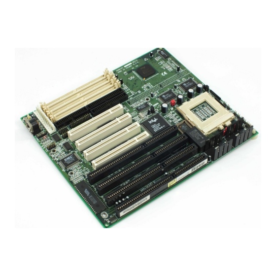
Page 12: Board Layout
Board Layout Power Connector Bank 0 Bank 1 Intel SB82371SB BIOS Pin 1 Intel FW82439HX JP10 JP12 SSM1 Pin 1 PBSRAM = Pipeline Burst SRAM... -
Page 13: System Memory
Bank 1, but you must populate a bank first before going to the next bank. The G586IPC system board can support 8MB to 256MB of memory us- ing 1MBx36, 2MBx36, 4MBx36, 8MBx36, or 16MBx36 72-pin SIMMs. The table below shows the supported SIM modules and their corre- sponding memory sizes. -
Page 14: Installing A Sim Module
Installing a SIM Module A SIM module simply snaps into a socket on the system board. Pin 1 of the SIM module must correspond with Pin 1 of the socket. notch 1. Position the SIMM above the socket with the “ notch” in the module aligned with the “... -
Page 15: Cache Memory
Cache Memory The G586IPC system board can support 256KB or 512KB pipeline burst, direct map write-back cache SRAM. Your system board may come with 0KB or 256KB cache mounted onboard. The 160-pin cache module slot lets you upgrade your cache memory by installing a 256KB or 512KB cache module. -
Page 16: Cpu Installation
PCI Slot 4. CPU Installation The G586IPC allows for easy installation of CPUs. Make sure all jump- ers are set correctly before applying power or you may damage the CPU or system board. Please see the jumper settings below. -
Page 17: Installing Upgrade Cpus
JP9: 5-6 On Installing Upgrade CPUs The G586IPC is equipped with a 321-pin Zero Insertion Force (ZIF) socket at location U27 of the system board. Refer to page 12 for the location of the ZIF socket. This socket is designed for easy removal of an old CPU and easy insertion of an upgrade CPU. - Page 18 Warning: Open the socket only if you are actually installing a CPU. The warranty on the original CPU will be voided if the S/N seal is broken. Do not change any factory CPU speed jumper settings if you are install- ing the 3.3V Pentium upgrade processor.
- Page 19 To install an upgrade CPU, do the following. 1. Make sure the handle on the side of the ZIF socket is up. To raise the handle, push it down, slightly pull it out to the side, then raise it as far as it will go. It may be necessary to initially apply a small amount of sideways force to free the handle from its retaining “...
- Page 20 3. Position the CPU above the ZIF socket. Make sure pin 1 of the CPU is aligned with pin 1 of the socket. Lower the chip until the pins are inserted properly in their corresponding holes. Remember that very little force is needed to install the CPU. If the CPU is not easily inserted, verify whether or not pin 1 of the CPU is aligned with pin 1 of the socket.
-
Page 21: Jumper Settings For Password Clear And Display Type
Fan Exhaust The CPU must be kept cool by using a fan with heatsink. The tempera- ture of the air entering the fan/heatsink cannot exceed 45°C (113°F). The ambient or room temperature must be below 37°C (99°F). In order to provide proper airflow to the CPU, all movable obstructions (power supply cables, cards, floppy disk cables) must be clear of the CPU fan/heatsink component in accordance with the space clearance discussed in the Clearance Requirements section of this manual. -
Page 22: Built-In Ports
Built-in Ports The G586IPC system board is equipped with two serial ports, one par- allel printer port, one FDD connector, two IDE hard disk shrouded head- ers and one PS/2 mouse connector. Refer to page 12 for the locations of the built-in connectors and pin 1 of those connectors. -
Page 23: Ps/2 Mouse Port
PS/2 Mouse Port The PS/2 mouse port is a 6-pin connector on the system board. Attach the 6-pin mouse port cable, which came with the G586IPC, to connector J1. Make sure the brown wire on the PS/2 mouse connector is aligned with pin 1 of connector J1. -
Page 24: Ide Hard Disk Interface
The end-most connector should be attached to the drive you want to designate as Drive A. IDE Hard Disk Interface The G586IPC system board is equipped with two PCI IDE shrouded headers that will interface four IDE (Integrated Drive Electronics) hard disk drives. - Page 25 Follow the instructions provided by the drive manu- facturer for setting the jumpers and/or switches on the drives. No changes are needed on the G586IPC system board when adding a sec- ond hard drive. We recommend that the IDE hard drives be from the same manufac- turer.
-
Page 26: Installing Expansion Cards
Installing Expansion Cards The G586IPC system board is equipped with 3 dedicated PCI slots, 3 dedicated 16-bit ISA slots and 1 shared PCI/ISA slot. All PCI slots are bus masters. You can only install one card in one or the other of the shared slots at a time;... -
Page 27: Chapter 3: Software Installation
Chapter 3 Software Installation After you power up your system, the BIOS message appears on your screen and the memory count begins. After the memory test, the following message will appear on the screen: Press DEL to enter setup If the message disappears before you respond, restart your system or press the “... -
Page 28: Standard Cmos Setup
Use the arrow keys to highlight the option you want and press <Enter>. The following describes each of these options. Standard CMOS Setup Use the arrow keys to highlight “ Standard CMOS Setup” and press <Enter>. A screen similar to the one below will appear. Date and Time This selection sets the time and date for the system. - Page 29 you can select Auto, User, one of 46 predefined drive specifications or None. Auto: This option indicates that the parameters for your hard disk drive(s) will be automatically detected and displayed when you boot your system. By default, the LBA mode is selected for a hard disk drive larger than 528 megabytes.
-
Page 30: Bios Features Setup
No Errors: The system boot will not stop for any detected errors. All Errors: The system will stop whenever the BIOS detects a non-fatal error. All, But Keyboard: The system will stop for any error except a keyboard error. All, But Diskette: The system will stop for any error except a disk error. All, But Disk/Key: The system will stop for any error except a keyboard or disk error. -
Page 31: Chipset Features Setup
Chipset Features Setup The G586IPC uses the Intel 82430HX chipset. The Chipset Features Setup allows you to modify some functions to optimize system perfor- mance. If you press <Enter>, a screen similar to the one on the next... -
Page 32: Power Management Setup
Use the arrow keys to move the highlight bar to the option you wish to change or modify. Use the <Page Up>, <Page Down>, <+> or <-> keys to make the corresponding changes. If the changes you made are incorrect or you change your mind, press <F6>... -
Page 33: Pci Configuration Setup
PCI Configuration Setup Use the arrow keys to highlight “ PCI Configuration Setup” and press <Enter>; a screen similar to the one below will appear. The PCI Configuration Setup allows you to assign INT A, B, C or D to the hard drives installed in your system. -
Page 34: I/O Configuration Setup
Highlight this option on the main menu and press <Enter>. The mes- sage below will appear. Load Setup Defaults (Y/N)? N Type <Y> and press <Enter> to load the Setup default values. PnP Configuration Setup Use the arrow keys to highlight “ PnP Configuration Setup” and press <Enter>. -
Page 35: Supervisor Password
The I/O Configuration Setup allows you to enable, disable or select the port address of the built-in serial ports, parallel port and floppy disk controller. Supervisor Password If you want to protect your system and setup from unauthorized entry, set a supervisor’ s password with the “ System” option selected in the BIOS Features Setup. -
Page 36: User Password
To delete or disable the password function, highlight “ Supervisor Pass- word” and press <Enter>, instead of typing in a new password. Press the <Esc> key to return to the main menu. If you forget your password, you should clear any previously set pass- word by setting Jumper JP3 to On for approximately two minutes. - Page 37 Standard CMOS Setup. Hard Drive Mode The G586IPC supports three HDD modes: Normal, LBA and Large. If your hard disk drive does not support LBA mode, the “ LBA” option will not be displayed. If your HDD has 1024 or fewer cylinders, the “ Large”...
- Page 38 Large Mode The Large mode is the extended HDD access mode supported by the G586IPC system board. Some IDE HDDs have more than 1024 cylin- ders without LBA support (in some cases, you may not want the LBA mode). This system board provides another alternative to support these kinds of HDDs.
-
Page 39: Save & Exit Setup
Maximum HDD size: no. Cylinders (1024) x no. Heads ( 32) x no. Sectors ( 63) x bytes per sector ( 512) 1 gigabyte Note: To support LBA or Large mode, address translation software is included in the Award BIOS HDD Sevice Routine (INT13h). If you are running an operating system that bypasses the BIOS Int13 Service Routine, LBA and Large Mode may fail. -
Page 40: System Error Report
System Error Report When the BIOS encounters an error that requires the user to correct something, either a beep code will sound or a message will be dis- played in a box in the middle of the screen and the message PRESS F1 TO CONTINUE, CTRL-ALT-ESC or DEL TO ENTER SETUP, will be shown in the information box at the bottom. - Page 41 DISPLAY TYPE HAS CHANGED SINCE LAST BOOT Since last powering off the system, the display adapter has been changed. You must configure the system for the new display type. ERROR ENCOUNTERED INITIALIZING HARD DRIVE The hard drive cannot be initialized. Be sure the adapter is installed correctly and all cables are correctly and firmly attached.
-
Page 42: Ide Device Drivers
Press and hold down the CTRL, ALT and DEL keys simultaneously. IDE Device Drivers To install the IDE device drivers supported by the G586IPC system board, please refer to the “ Readme” file contained in the provided dis- kette. -
Page 43: Chapter 4: Troubleshooting Checklist
Chapter 4 Troubleshooting Checklist If you experience difficulty with the G586IPC system board, please refer to the checklist below. If you still cannot identify the problem, please contact your dealer. 1. Check the jumper settings to ensure that the jumpers are properly set. -
Page 44: Appendix A: Types Of Sim Modules
Appendix A Types of Modules The G586IPC system board allows you to populate memory with 1MBx36, 2MBx36, 4MBx36, 8MBx36, and 16MBx36 SIMMs. The follow- ing modules have been tested with this board. Most untested brands will work but a few may fail to do so. -
Page 45: Appendix B: Memory And I/O Maps
Appendix B Memory and I/O Maps Memory Address Map Address Name Function 0000000 to 640KB System System Board Memory 009FFFF Board RAM 00A0000 to 128KB Video Reserved for Graphics 00BFFFF Display Memory Display Memory 00C0000 to 160KB I/O Reserved for ROM on 00E7FFF Expansion ROM I/O Adapter Card... - Page 46 I/O Address Map I/O Address Function 000-01F DMA Controller 1, 8237A-5 020-03F Interrupt Controller 1, 8259A, Master 040-05F Timer, 8254-2 060-06F 8742 (Keyboard Controller) 070-07F Real-time Clock, NMI (Non-maskable Interrupt) Mask 080-09F DMA Page Memory, 74LS612 0A0-08F Interrupt Controller 2, 8259A 0C0-0DF DMA Controller 2, 8237A-5 Shadow RAM and Cache Control Bit...
-
Page 47: Appendix C: Pci I/O Pin Assignments
Appendix C PCI I/O Pin Assignments Component Side Solder Side -12V - 01 - TRST# - 02 - +12V Ground - 03 - - 04 - - 05 - INTA# - 06 - INTB# - 07 - INTC# INTD# - 08 - PRSNT1# - 09 - Reserved... -
Page 48: Appendix D: Isa I/O Pin Assignments
Appendix D ISA I/O Pin Assignments -I/O Chck - 01 - Reset Drv - 02 - +5V DC - 03 - IRQ9 - 04 - -5V DC - 05 - DRQ2 - 06 - -12V DC - 07 - O W S - 08 - +12V DC - 09 -... -
Page 49: Appendix E System Overview
Appendix E System Overview DMA Controller 2 DMA Controller 1 Ch4-Cascade for CTRL 1 Ch0-Reserved for User Ch5-Reserved for User Ch1-Reserved for User Ch6-Reserved for User Ch2-Diskette Ch7-Reserved for User Ch3-Reserved for User Note: DMA controller 1 supports 8-bit data transfer. DMA controller 2 supports 16-bit data transfer. -
Page 50: System Interrupts
System Interrupts Interrupt Controller 1 Interrupt Controller 2 IRQ9-Software Redirected IRQ0-Timer Output (Out 0) IRQ1-Keyboard (Output Buffer to INT 0AH (IRQ2) IRQ10-Reserved Full) IRQ2-Interrupt from INTR2 IRQ11-Reserved IRQ3-Serial Port 2 IRQ12-PS/2 Mouse IRQ4-Serial Port 1 IRQ13-Coprocessor IRQ5-Parallel Port 2 or 3 * IRQ14-Primary Fixed Disk IRQ6-Diskette Controller Controller (1F0) -
Page 51: Appendix F: Connector Pin Assignments
Appendix F Connector Pin Assignments Connector J1 PS/2 Mouse Connector Function Mouse Data Reserved Ground Mouse Clock Reserved J2 (COM1) and J3 (COM2) COM 1 and COM 2 Serial Ports Function DCD (Data Carrier Detect) RX (Receive Data) TX (Transmit Data) DTR (Data Terminal Ready) Ground (Signal Ground) DSR (Data Set Ready) - Page 52 Function Function Ground Wr Protect Write Data Ground Ground Read Data Write Gate Ground Ground Head Select Track 0 Ground MSEN Disk Change Connector J5 Parallel Printer Port Function Function -Strobe -Autofd -Error Data 0 Data 1 -Init -Slctin Data 2 Data 3 Ground Data 4...
- Page 53 Function Reserved Ground IOCS16 Reserved HCS0 HCS1 Ground Connector J8 Fan Connector Function Ground +12V Ground Connector J10 Primary/Secondary IDE LED Connector Function Signal Connector J11 Green LED Connector Function Signal...
- Page 54 Connector J13 Green Button Connector Function Ground Signal Connector J14 Reset Switch Connector Function Ground Reset Connector J15 Speaker Connector Function Signal Ground Signal Ground Connector J16 Power LED/Keylock Connector Function LED Signal Reserved Ground Keylock Signal Ground...
- Page 55 Connector CN1 PS/2 Keyboard Connector Function Keyboard Data Reserved Ground Keyboard Clock Reserved Connector CN2 AT Keyboard Connector Function Keyboard Clock Keyboard Data Reserved Ground Connector PL1 Power Connector Function Power Good +12V -12V Ground Ground Ground Ground...
- Page 56 Connector SSM1 Cache Module Slot Function Function Ground TIO0 Ground TIO2 TIO6 TIO4 TIO8 VCC3 VCC3 TWE# CADS#/CAA3 Ground Ground HBE4# HBE6# HBE0# HBE2# VCC3 VCC3 CCS#/CAB4 GWE# Ground BWE# Ground VCC3 VCC3 Ground Ground VCC3 ADSP# ECS1#/(CS#) ECS2# Ground Ground Ground TIO1...
- Page 57 Function Function HBE7# HBE1# Ground VCC5 HBE3# CAB3 CALE VCC5 Ground RSVD Ground VCC5 VCC5 Ground Ground RSVD VCC5 Ground CLK0 Ground Ground VCC5 VCC5 Ground Ground...
-
Page 58: Appendix G: Award Bios Hard Disk Table
Appendix G Award BIOS Hard Disk Table Example Type Size Cylinders Heads Sectors Write Land Model (MB) Precomp Zone TEAC SD510, MMI 112, 5412 Seagate ST225, ST4026 None Seagate ST125, Tandon TM262 None Tandon TM 703 None None None None Disctron 526, MMI M125 None... - Page 59 Example Type Cylinders Heads Sectors Write Land Size Model (MB) Precomp Zone Seagate ST4038 1024 None Seagate ST4051 1224 None 1023 Seagate ST4096 1224 None 1223 Maxtor 2085 1224 None 1223 Maxtor 2140, Priam S14 1024 None 1223 Maxtor 2190, Priam S19 None 1024...
- Page 60 Example Type Size Cylinders Heads Sectors Write Land Model (MB) Precomp Zone Miniscribe 3053/ 1024 None 1023 6053 RLL Miniscribe 3650 None None Miniscribe 3675 Conner CP3104 None Conner CP3204 None (User Defined)
Need help?
Do you have a question about the G586IPC and is the answer not in the manual?
Questions and answers