Table of Contents
Advertisement
Quick Links
Advertisement
Table of Contents

Related Manuals for DFI G586IPC


Summary of Contents for DFI G586IPC
- Page 1 G586IPC Rev . D + System Board User’ s Manual - 30170305 -...
- Page 2 FCC Statement on Class B This equipment has been tested and found to comply with the limits for a Class B digital device, pursuant to Part 15 of the FCC rules. These limits are designed to provide reasonable protection against harmful in- terference when the equipment is operated in a residential installation.
-
Page 3: Table Of Contents
Table of Contents Chapter 1: Introduction ............5 Features and Specifications ..........6 Package Checklist .............. 8 Chapter 2: Hardware Installation ..........9 Preparing the Area.............. 9 Handling the System Board ..........9 Installing the System Board ..........10 Board Layout ..............12 System Memory ..............13 Installing a SIM Module ..........15 Cache Memory ..............15... - Page 4 Load Setup Defaults .............44 Integrated Peripherals ...........45 Supervisor Password ............47 User Password ............48 IDE HDD Auto Detection ..........48 HDD Low Level Format ..........51 Save & Exit Setup ............52 Exit Without Saving............52 Desktop Management Interface (DMI) ........52 System Error Report ............56 Driver Installation ...............57 Chapter 4: Troubleshooting Checklist ..........
-
Page 5: Chapter 1 Introduction
PR120+/PR133+/PR150+/PR166+ and AMD-K5™ PR75/PR90/PR100/PR120/PR133 processors. The G586IPC supports 8MB to 256MB of system memory using EDO or fast page mode DRAM. It is equipped with 4 SIMM sockets allowing you to install x32 or x36 SIMMs. The x36 SIMM supports parity check- ing which informs the user of memory failure and prevents error accu- mulation. -
Page 6: Features And Specifications
Features and Specifications Processor ® • Intel Pentium processor with MMX technology - 166/200MHz ® • Intel Pentium 75/90/100/120/133/150/166/200MHz ® • Future Pentium OverDrive processor ® • Cyrix 6x86 PR120+/PR133+/PR150+/PR166+ • AMD-K5™ PR75/PR90/PR100/PR120/PR133 Chipset ® • Intel 82430HX PCIset Cache Memory •... - Page 7 PCI IDE Interface • PIO Mode 3 and Mode 4 Enhanced IDE (data transfer rate up to 16.6MB/sec.) • DMA Mode 2 Bus Master IDE (data transfer rate up to 22.2MB/sec.) • Bus mastering reduces CPU utilization during disk transfer •...
-
Page 8: Package Checklist
Package Checklist The G586IPC package contains the following items: • The G586IPC system board • The G586IPC user’ s manual • Serial, mouse and printer port cables Option 1: - One card-edge bracket with a 9-pin and 25-pin serial port cables... -
Page 9: Chapter 2: Hardware Installation
Chapter 2 Hardware Installation This chapter summarizes the steps to install the G586IPC system board into your system unit. It also includes a description of the area in which you must work and directions for memory installation. Before installing the system board, obtain the memory you plan to install. Refer to the System Memory section for the number and type of SIM modules needed for the amount of memory you require. -
Page 10: Installing The System Board
ESD protection. Installing the System Board If you are installing the G586IPC system board, the following outlines the basic installation steps. Before installing the system board into your system unit, you should prepare the tools you will need. - Page 11 9-10 for proper handling tech- niques. 6. Insert the SIMMs into the SIMM banks on the G586IPC. The quan- tity and location of the SIMMs depends on the memory configura- tion and type of modules you intend to use.
-
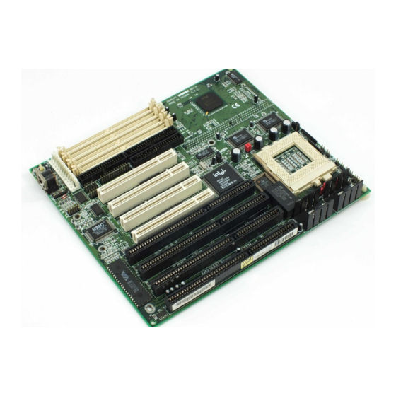
Page 12: Board Layout
Board Layout square denotes pin 1... -
Page 13: System Memory
Bank 0 or Bank 1, but you must populate one bank first before going to the next bank. The G586IPC system board can support 8MB to 256MB of memory us- ing 1MBx32/x36, 2MBx32/x36, 4MBx32/x36, 8MBx32/x36, or 16MBx32/ x36 72-pin SIMMs. The table below shows the supported SIM modules and their corresponding memory sizes. - Page 14 Bank 0 Bank 1 SIMM4 Memory Size SIMM3 SIMM1 SIMM2 4MBx32/x36 32MB 4MBx32/x36 — — — 32MB — 4MBx32/x36 4MBx32/x36 2MBx32/x36 32MB 2MBx32/x36 2MBx32/x36 2MBx32/x36 1MBx32/x36 4MBx32/x36 40MB 1MBx32/x36 4MBx32/x36 4MBx32/x36 1MBx32/x36 40MB 4MBx32/x36 1MBx32/x36 2MBx32/x36 4MBx32/x36 48MB 2MBx32/x36 4MBx32/x36 4MBx32/x36 4MBx32/x36 2MBx32/x36...
-
Page 15: Installing A Sim Module
Tilt the module upright until it locks in place in the socket. Cache Memory The G586IPC system board can support 256KB or 512KB pipeline burst, direct map write-back cache SRAM. Your system board may come with 256KB or 512KB cache mounted at locations U22 and U23 of the system board. -
Page 16: Installing The Cache Module
Please see the jumper settings on the following pages. Use the needle-nosed pliers to move the jumpers if necessary. The table below shows the External Bus Clock of the CPUs supported by the G586IPC sys- tem board and their corresponding PCI Clock and Bus Clock. -
Page 17: Jumper Settings For Intel Cpus
Jumper Settings for Intel Processors Intel Processors Ext. Bus 75MHz 50MHz 1-2 On, 3-4 On 90/120/150MHz 60MHz 1-2 On, 3-4 Off 100/133/166/200MHz 66MHz 1-2 Off, 3-4 On MMX-166/200MHz Freq. Ratio Intel Processors JP12 1.5x 75/90/100MHz 1-2 Off, 3-4 Off JP12 120/133MHz 1-2 On, 3-4 Off 150/166MHz/MMX-166MHz... -
Page 18: Jumper Settings For Cyrix Cpus
Jumper Settings for Cyrix Processors Ext. Bus Cyrix Processors PR120+ 50MHz 1-2 On, 3-4 On 55MHz 1-2 Off, 3-4 Off PR133+ PR150+ 60MHz 1-2 On, 3-4 Off PR166+ 66MHz 1-2 Off, 3-4 On Cyrix Processors Freq. Ratio JP12 JP12 PR120+/PR133+/ 1-2 On, 3-4 Off PR150+/PR166+ JP20... -
Page 19: Jumper Settings For Amd-K5 Cpus
Jumper Settings for AMD-K5 Processors P-Rating/Core MHz Ext. Bus PR75/75MHz 50MHz 1-2 On, 3-4 On PR90/90MHz 60MHz 1-2 On, 3-4 Off PR100/100MHz 66MHz 1-2 Off, 3-4 On PR120/90MHz 60MHz 1-2 On, 3-4 Off PR133/100MHz 66MHz 1-2 Off, 3-4 On P-Rating/Core MHz Freq. -
Page 20: Installing Upgrade Cpus
Installing Upgrade CPUs The G586IPC is equipped with a 321-pin Zero Insertion Force (ZIF) socket at location U27 of the system board. Refer to page 12 for the location of the ZIF socket. This socket is designed for easy removal of an old CPU and easy insertion of an upgrade CPU. - Page 21 amount of sideways force to free the handle from its retaining “ tab” . Once clear of the “ tab” , the handle will open relatively easily. The top plate will slide back. Do not use screwdrivers or other tools to open the socket, or you may damage the system or socket.
-
Page 22: Installing Fan/Heatsink For Cyrix Cpus
Pin 1 Positioning the CPU Above the ZIF Socket 4. Push the handle down until the handle locks into place. The top plate will slide forward. You will feel some resistance as pressure starts to secure the CPU in the socket. This is normal and will not damage the CPU. -
Page 23: Jumper Settings For Cmos Clear
inches. All cables (for floppy drive, hard drive, CD-ROM, etc.) must be routed clear of the CPU and its airspace. Fan Exhaust The CPU must be kept cool by using a fan with heatsink. The tempera- ture of the air entering the fan/heatsink cannot exceed 45 C (113 The ambient or room temperature must be below 37 C (99... -
Page 24: Built-In Ports
Built-in Ports The G586IPC system board is equipped with two serial ports, one par- allel printer port, one shrouded floppy disk header, two shrouded IDE hard disk headers, one PS/2 mouse port and two connectors for exter- nal USB ports. Refer to page 12 for the locations of the built-in connec- tors and pin 1 of those connectors. -
Page 25: Parallel Port
278-27A Hex Connecting the Parallel Printer Port Attach the DB-25 printer port cable to connector J5 on the G586IPC system board. Make sure the colored stripe on the ribbon cable aligns with pin 1 of connector J5. Use a small nutdriver to mount the cable into a DB-25 cutout in the system chassis. -
Page 26: Ide Hard Disk Interface
IDE Hard Disk Interface The G586IPC system board is equipped with two shrouded PCI IDE headers that will interface up to four Enhanced IDE (Integrated Drive Electronics) hard disk drives. Note: Only Enhanced IDE hard drives or ATAPI CD-ROMs can be connected to the IDE interface. - Page 27 In a few cases, drives from two different manufacturers will not function properly when used together. The problem lies in the hard drives, not the G586IPC system board. Preparing an IDE Drive for Use IDE disk drives are already low-level formatted, with any bad-track er- rors entered, when shipped by the drive manufacturer.
-
Page 28: Universal Serial Bus Connectors
Master mode. Universal Serial Bus Connectors The G586IPC system board is equipped with two connectors, at loca- tions JP1 and JP2 on the system board, for external USB ports. USB allows data exchange between your computer and a wide range of simultaneously accessible peripherals. -
Page 29: Installing Expansion Cards
USB port cables (optional) Installing Expansion Cards The G586IPC system board is equipped with 3 dedicated PCI slots, 3 dedicated 16-bit ISA slots and 1 shared PCI/ISA slot. All PCI slots are bus masters. You can only install one card in one or the other of the shared slots at a time;... -
Page 30: Chapter 3: Software Installation
Chapter 3 Software Installation After you power up your system, the BIOS message appears on your screen and the memory count begins. After the memory test, the following message will appear on the screen: Press DEL to enter setup If the message disappears before you respond, restart your system or press the “... -
Page 31: Standard Cmos Setup
ROM PCI/ISA BIOS CMOS SETUP UTILITY AWARD SOFTWARE, INC. STANDARD CMOS SETUP INTEGRATED PERIPHERALS SUPERVISOR PASSWORD BIOS FEATURES SETUP CHIPSET FEATURES SETUP USER PASSWORD POWER MANAGEMENT SETUP IDE HDD AUTO DETECTION PNP/PCI CONFIGURATION HDD LOW LEVEL FORMAT LOAD BIOS DEFAULTS SAVE &... - Page 32 Date The date format is <day>, <month>, <date>, <year>. Displays a day, from Sunday to Saturday Displays the month, from January to December Month Displays the date, from 1 to 31 Date Displays the year, from 1900 to 2099 Year Time The time format is <hour>, <minute>, <second>.
- Page 33 If the controller of the HDD interface is ESDI, you must select “ Type 1” . If the controller of the HDD interface is SCSI, you must select “ None” . If you select Type “ Auto” , the BIOS will auto-detect the HDD & CD-ROM drive at the POST stage and show the IDE for the HDD &...
- Page 34 Video This category selects the type of video adapter used for the primary system monitor. Although secondary monitors are supported, you do not have to select the type in Setup. The default setting is EGA/VGA (BIOS default, Setup default). Enhanced Graphics Adapter/Video Graphics Array. For EGA, EGA/VGA VGA, SEGA, SVGA and PGA monitor adapters.
-
Page 35: Bios Features Setup
Base This refers to the amount of base or conventional memory Memory installed on the system board. Extended This is the amount of memory located above 1MB in the Memory memory address map of the CPU. Other This memory size refers to the memory located in the ad- Memory dress space between 640K and 1024K. - Page 36 ! WARNING ! Disk boot sector is to be modified Type “ Y” to accept write or “ N” to abort write Award Software, Inc. After seeing this message, if necessary, you will be able to run an anti- virus program to locate and remove the problem before any damage is done.
-
Page 37: Boot Sequence
Boot Sequence This category determines which drive to search first for the disk operat- ing system (i.e. DOS). The default is A, C. A, C The system will first search for a floppy drive and then a hard disk drive. C, A The system will first search for a hard disk drive and then a floppy drive. -
Page 38: Security Option
Boot Up NumLock Status This allows you to determine the default state of the numeric keypad. By default, the system boots up with NumLock on. The function of the numeric keypad is the number keys. The function of the numeric keypad is the arrow keys. Security Option This category allows you to limit access to your system and Setup or just to Setup. -
Page 39: Chipset Features Setup
Enabled Video shadow is enabled. Disabled Video shadow is disabled. C8000-CBFFF Shadow to DC000-DFFFF Shadow These categories determine whether option ROMs will be copied to RAM. Enabled Optional shadow is enabled. Optional shadow is disabled. Disabled Chipset Features Setup This section gives you instructions on how to configure the system based on the specific features of the chipset. -
Page 40: Power Management Setup
Power Management Setup Power Management Setup allows you to configure your system to most effectively save energy. ROM PCI/ISA BIOS POWER MANAGEMENT SETUP AWARD SOFTWARE, INC. ** Power Down & Resume Events ** Power Management : Disabled IRQ3 (COM 2) : On PM Control by APM : Yes... -
Page 41: Video Off Method
Video Off Method This determines the manner in which the monitor is blanked. This selection will cause the system to turn off the vertical and SYNC + horizontal synchronization ports and write blanks to the video Blank buffer. Blank This option only writes blanks to the video buffer. Screen DPMS Initializes display power management signaling. -
Page 42: Pnp/Pci Configuration Setup
IRQ3-IRQ15 (Wake Up Events in Doze & Standby, and Power Down & Resume Events) These are I/O events whose occurrence can prevent the system from entering a power saving mode or can awaken the system from such a mode. In effect, the system remains alert for anything which occurs to a device which is configured as enabled, even when the system is in a power saving mode. - Page 43 Resources Controlled By The Award Plug and Play BIOS has the capacity to automatically con- figure all of the boot and Plug and Play compatible devices. However, this capability means absolutely nothing unless you are using a Plug ® and Play operating system such as Windows Auto The system will automatically detect the settings for you.
-
Page 44: Load Bios Defaults
Primary IDE INT# and Secondary IDE INT# The Primary and Secondary IDE INT# categories are used to select the PCI interrupt (A, B, C, or D) that is associated with the connected hard drives. Load BIOS Defaults The “ Load BIOS Defaults” option loads the troubleshooting default val- ues permanently stored in the ROM chips. -
Page 45: Integrated Peripherals
Integrated Peripherals ROM PCI/ISA BIOS INTEGRATED PERIPHERALS AWARD SOFTWARE, INC. IDE HDD Block Mode : Enabled USB Controller : Disabled PCI Slot IDE 2nd Channel : Disabled : Enabled On-Chip Primary PCI IDE : Enabled On-Chip Secondary PCI IDE : Auto IDE Primary Master PIO IDE Primary Slave PIO : Auto... - Page 46 To use the IrDA function, follow the steps below. 1. Connect your IrDA cable to connector J9 of the G586IPC system board. Refer to page 12 for the location of connector J9. 2. Set “ Onboard UART 2 Mode” to the type of IrDA standard sup-...
-
Page 47: Supervisor Password
You may not use IrDA (J9) and the COM 2 serial port (J3) at the same time. If you are using the COM 2 serial port, set “ Onboard UART 2 Mode” to Standard. Standard Uses the COM 2 serial port. HPSIR HP mode IrDA. -
Page 48: User Password
Type in the password. You are limited to eight characters. When done, the message below will appear: Confirm Password: You are being asked to verify the password. Type in exactly the same password. If you type in a wrong password, you will be prompted to enter the correct password again. -
Page 49: Normal Mode
ROM PCI/ISA BIOS CMOS SETUP UTILITY AWARD SOFTWARE, INC. HARD DISKS TYPE SIZE CYLS HEAD RECOMP LANDZ SECTOR MODE Primary Master: Select Primary Master Option (N=Skip): N OPTIONS SIZE CYLS HEAD RECOMP LANDZ SECTOR MODE 2 (Y) 1653 1654 65535 1653 Normal 65536... - Page 50 If you set your HDD to Normal mode, the maximum accessible HDD will be 528 megabytes even though the physical size of the HDD may be greater than that. LBA (Logical Block Addressing) Mode LBA mode is a HDD accessing method to overcome the 528 megabyte limitation.
-
Page 51: Hdd Low Level Format
Maximum HDD size: no. Cylinders (1024) x no. Heads ( 32) x no. Sectors ( 63) x bytes per sector ( 512) 1 gigabyte Note: To support LBA or Large mode, address translation software is included in the Award BIOS HDD Sevice Routine (INT13h). If you are running an operating system that bypasses the BIOS Int13 Service Routine, LBA and Large Mode may fail. -
Page 52: Save & Exit Setup
<Del> after memory testing is done. Desktop Management Interface (DMI) The G586IPC system board comes with a DMI built into the BIOS. DMI, along with the appropriately networked software, is designed to make inventory, maintenance and troubleshooting of computer systems easier. -
Page 53: Using The Dmi Utility
Running the DMI Utility To run the DMI utility, type: DMICFG.EXE. You can download this utility from http://www.dfi.com.tw - BIOS & DRIVERS section or ftp.dfiusa.com - /pub/DMI directory. The DMI utility must run in real mode with at least 180K of base memory. - Page 54 The commands at the bottom of the screen will allow you to navigate through the various setup menus. Edit DMI 1. Use the ← or → arrow keys to select the Edit DMI menu. 2. Highlight the item on the left screen that you would like to edit by using the ↑...
- Page 55 3. The DMI files will appear on the screen. Select the file you would like to load and press <Enter>. 4. The following message will appear. Do you want to execute? (Y/N) Type <Y>. All previous DMI structures will be destroyed and the new file will be saved into the flash ROM.
-
Page 56: System Error Report
System Error Report When the BIOS encounters an error that requires the user to correct something, either a beep code will sound or a message will be dis- played in a box in the middle of the screen and the message, PRESS F1 TO CONTINUE, CTRL-ALT-ESC or DEL TO ENTER SETUP, will be shown in the information box at the bottom. -
Page 57: Driver Installation
The checksum of ROM address F0000H-FFFFFH is bad. Memory test fail BIOS reports memory test fail if the memory has error(s). Driver Installation To install the IDE drivers supported by the G586IPC system board, please refer to the “ Readme” file contained in the provided diskettes. -
Page 58: Chapter 4: Troubleshooting Checklist
Chapter 4 Troubleshooting Checklist This chapter of the manual is designed to help you with problems that you may encounter with your personal computer. To efficiently troubleshoot your system, treat each problem individually. This is to ensure an accurate diagnosis of the problem in case a problem has multiple causes. - Page 59 The picture seems to be constantly moving. 1. The monitor has lost its vertical sync. Adjust the monitor’ s vertical sync. 2. Move away any objects, such as another monitor or fan, that may be creating a magnetic field around the display. The screen seems to be constantly wavering.
- Page 60 Hard Drive Hard disk failure. 1. Make sure the correct drive type for the hard disk drive has been entered in the BIOS. 2. If the system is configured with two hard drives, make sure the bootable (first) hard drive is configured as Master and the second hard drive is configured as Slave.
- Page 61 3. Verify that the attached serial device works by attaching it to a serial port that is working and configured correctly. If the serial device does not work, either the cable or the serial device has a problem. If the serial device works, the problem may be due to the onboard I/O or the address setting.
-
Page 62: Appendix A: Types Of Modules
Appendix A Types of Modules The following modules have been tested with this board. Most untested brands will work but a few may fail to do so. SIMM Brand Chip Number 1MBx32/x36 Fujitsu 81C1000A-70 M51440A-70 2MBx32/x36 M511000B-70 424400-60 Micron 40447-60 TMS4400DJ-70 Micron MT4C4007-70 (EDO) -
Page 63: Appendix B: Memory And I/O Maps
Appendix B Memory and I/O Maps Memory Address Map Address Name Function 0000000 to 640KB System System Board Memory 009FFFF Board RAM 00A0000 to 128KB Video Reserved for Graphics 00BFFFF Display Memory Display Memory 00C0000 to 160KB I/O Reserved for ROM on 00E7FFF Expansion ROM I/O Adapter Card... - Page 64 I/O Address Map I/O Address Function 0000-001F DMA Controller 1, 8237A-5 0020-003F Interrupt Controller 1, 8259A, Master 0040-005F Timer, 8254-2 0060-006F 8742 (Keyboard Controller) 0070-007F Real-time Clock, NMI (Non-maskable Interrupt) Mask 0080-009F DMA Page Memory, 74LS612 00A0-00BF Interrupt Controller 2, 8259A 00C0-00DF DMA Controller 2, 8237A-5 00E8...
-
Page 65: Appendix C Connectors
Appendix C Connectors Connectors PS/2 mouse connector COM 1 serial port COM 2 serial port Floppy disk drive connector Parallel printer port Primary IDE hard disk drive connector Secondary IDE hard disk drive connector Fan connector Infrared connector Primary/Secondary IDE LED connector Green LED connector Green button connector Reset switch connector... -
Page 66: Pin Assignment
Pin Assignment J10 - IDE LED connector J11 - Green LED connector Function Function Signal Signal J13 - Green button connector J14 - Reset switch connector Function Function Ground Ground Signal Reset J9 - Infrared connector J16 - Power LED/Keylock Function Function IrTX... - Page 67 J1 - PS/2 mouse connector Function Mouse Data Reserved Ground Mouse Clock Reserved JP1 - USB connector Function -Data +Data Ground Ground JP2 - USB connector Function -Data +Data Ground...
Need help?
Do you have a question about the G586IPC and is the answer not in the manual?
Questions and answers