DFI G586IPV User Manual
Hide thumbs
Also See for G586IPV:
- User manual (68 pages) ,
- User manual (61 pages) ,
- User manual (48 pages)
Table of Contents
Advertisement
Quick Links
Download this manual
See also:
User Manual
Advertisement
Table of Contents

Related Manuals for DFI G586IPV


Summary of Contents for DFI G586IPV
- Page 1 G586IPV Rev . A+ System Board User’ s Manual -L31060618-...
- Page 2 FCC Statement on Class B This equipment has been tested and found to comply with the limits for a Class B digital device, pursuant to Part 15 of the FCC rules. These limits are designed to provide reasonable protection against harmful interference when the equipment is operated in a residential installation.
-
Page 3: Table Of Contents
Table of Contents Chapter 1: Introduction ............5 Features and Specifications ..........6 Package Checklist .............. 8 Chapter 2: Hardware Installation ..........9 Preparing the Area.............. 9 Handling the System Board ..........9 Installing the System Board ..........10 Board Layout ..............12 System Memory ..............13 DIMM ................13 SIMM ................14... - Page 4 Integrated Peripherials ...........48 Supervisor Password ............51 User Password ............52 IDE HDD Auto Detection ..........53 HDD Low Level Detection ..........55 Save & Exit Setup ............56 Exit Without Saving............57 System Error Report ............57 IDE Device Drivers .............59 Chapter 4: Troubleshooting Checklist ..........60 Appendix A: Types of Modules ............61 Appendix B: Memory and I/O Maps ..........62 Appendix C: PCI I/O Pin Assignments ..........64...
-
Page 5: Chapter 1: Introduction
Cyrix 6x86 P120+/P133+/P150+/ P166+ and AMD-K5 PR75 75MHz/PR90 90MHz CPUs. The G586IPV can support 8MB to 128MB of system memory. It is equipped with a DIMM socket using x64 EDO, fast page mode or SDRAM, and 4 SIMM sockets using EDO or fast page mode x32 DRAM. This system board also supports pipeline burst SRAM, and provides easy cache upgrades using 256KB cache module. -
Page 6: Features And Specifications
Features and Specifications Processor • Intel Pentium™ 75/90/100/120/133/150/166/200MHz • Future Pentium™ OverDrive Processor • Cyrix 6x86 P120+/P133+/P150+/P166+ • AMD-K5 PR75 75MHz/PR90 90MHz Chipset • Intel 82430VX PCIset Cache Memory • Supports 256KB or 512KB pipeline burst, direct map write-back cache •... - Page 7 PCI IDE Interface • PIO Mode 3 and Mode 4 Enhanced IDE (data transfer rate up to 6.6MB/ sec.) • DMA Mode 2 Bus Master IDE (data transfer rate up to 22.2MB/sec.) • Bus mastering reduces CPU utilization during disk transfer •...
-
Page 8: Package Checklist
Package Checklist The G586IPV package contains the following items: • The G586IPV system board • The G586IPV user’ s manual • Two 40-pin IDE hard disk cable • One 34-pin floppy disk drive cable • One card-edge bracket with a 25-pin printer port cable •... -
Page 9: Chapter 2: Hardware Installation
Chapter 2 Hardware Installation This chapter summarizes the steps to install the G586IPV system board into your system unit. It also includes a description of the area in which you must work and directions for memory installation. Before installing the system board, obtain the memory you plan to install. -
Page 10: Installing The System Board
ESD protection. Installing the System Board If you are installing the G586IPV system board, the following outlines the basic installation steps. Before installing the system board into your system unit, you should prepare the tools you will need. - Page 11 4. Loosen the screws holding the original system board and remove the board from the system. Save the screws. 5. Remove the G586IPV from its original packing box. Be careful to avoid touching all connectors and pins on the board. Please refer to the han- dling instructions on pages 9-10 for proper handling techniques.
-
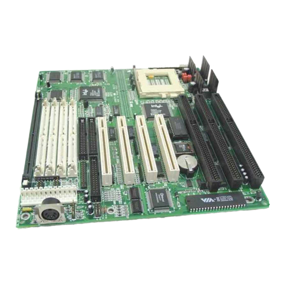
Page 12: Board Layout
Board Layout Wi n bond Battery SSM1 Intel SB82371SB Bank 1 Bank 0 JP10 JP11 Pin 1 " square denotes pin 1. 1. " 2. PBSRAM = Pipeline Burst SRAM... -
Page 13: System Memory
DIMM The DIMM (Dual In-line Memory Module) socket uses x64 EDO, FPM and SDRAM. The G586IPV system board can support 8MB to 16MB memory us- ing 1MBx64 or 2MBx64 168-pin DIMM. Refer to page 12 for the location of the DIMM. -
Page 14: Simm
You can install SIMMs in either of the banks, Bank 0 or Bank 1, but you must populate a bank first before going to the next bank. The G586IPV system board can support 8MB to 128MB of memory using 1MBx32, 2MBx32, 4MBx32, or 8MBx32 72-pin SIMMs. The table below shows the supported SIM modules and their corresponding memory sizes. -
Page 15: Jumper Settings For Dimm And Simm
Tilt the module upright until it locks in place in the socket. Warning: The DIMM and SIMM can not exist on the G586IPV system board at the same time. You must only use either a DIMM or SIMMs on your system board. -
Page 16: Cache Memory
Cache Memory The G586IPV system board can support 256KB or 512KB pipeline burst, di- rect map write-back cache SRAM. Your system board may come with 256KB or 512KB cache mounted onboard. The 160-pin cache module slot lets you upgrade your cache memory by installing a 256KB cache module. - Page 17 Note: With the cache module installed in the cache module slot, the components on the solder side of the add-in card in PCI Slot 3 must not protrude more than 5mm. The components of the component side of the add-in card in PCI Slot 2 also must not protrude more than 5mm.
-
Page 18: Cpu Installation
CPU Installation The G586IPV allows for easy installation of CPUs. Make sure all jumpers are set correctly before applying power or you may damage the CPU or system board. Please see the jumper settings on the following pages. Use the needle-nosed plier to move the jumpers if necessary. -
Page 19: Cyrix 6X86 Cpus
Cyrix 6x86 CPUs Cyrix 6x86CPUs CPU CLK P120+/P133+ 50/55MHz Cyrix 6x86CPUs CPU CLK Pin 1-2 Pin 3-4 P150+/P166+ 60/66MHz P120+ 50MHz P133+ 55MHz P150+ 60MHz Cyrix 6x86CPUs CPU CLK Pin 1-2 Pin 3-4 P166+ 66MHz P120+/P133+/ P150+/P166+ JP11 ↓ Voltage JP11 1-3 On, 2-4 On 2.8V... - Page 20 AMD-K5 CPUs AMD-K5 CPUs CPU CLK PR75 75MHz 50MHz PR90 90MHz 60MHz Pin 1-2 Pin 3-4 AMD-K5 CPUs CPU CLK CPU CLK Pin 1-2 Pin 3-4 AMD-K5 CPUs PR75 75MHz 50MHz 1.5x PR75 75MHz/ PR90 90MHz 60MHz PR90 90MHz JP11 ↓...
-
Page 21: Installing Upgrade Cpus
Installing Upgrade CPUs The G586IPV is equipped with a 321-pin Zero Insertion Force (ZIF) socket at location U25 of the system board. Refer to page 12 for the location of the ZIF socket. This socket is designed for easy removal of an old CPU and easy insertion of an upgrade CPU. - Page 22 To install an upgrade CPU, do the following. 1. Make sure the handle on the side of the ZIF socket is up. To raise the handle, push it down, slightly pull it out to the side, then raise it as far as it will go.
-
Page 23: Installing A Fan/Heatsink For Cyrix Cpus
3. Position the CPU above the ZIF socket. Make sure pin 1 of the CPU is aligned with pin 1 of the socket. Lower the chip until the pins are inserted properly in their corresponding holes. Remember that very little force is needed to install the CPU. - Page 24 Clearance Requirements Your CPU comes with a heatsink mounted on top. To maintain proper airflow once the upgrade is installed on the system board, the CPU and heatsink require certain space clearances. The clearance above the CPU’ s fan/heatsink must be at least 0.4 inches. The clearance on at least 3 of 4 sides of the processor and heatsink must be at least 0.2 inches.
-
Page 25: Jumper Settings For Password Clear And Display Type Select
Jumper Settings for Password Clear and Display Type Jumper JP2 Password Clear If you set a password in the "Password Setting" option and forget your pass- word. power off your system and set jumper JP2 to On to clear the password stored in your CMOS. -
Page 26: Built-In Ports
Built-in Ports The G586IPV system board is equipped with two serial ports, one parallel printer port, one FDD connector, two IDE hard disk shrouded headers and one PS/2 mouse connector. Refer to page 12 for the locations of the built-in connectors and pin 1 of those connectors. -
Page 27: Ps/2 Mouse Port
278-27A Hex Connecting the Parallel Printer Port Attach the DB-25S printer port cable to connector J7 on the G586IPV system board. Make sure the colored stripe on the ribbon cable aligns with pin 1 of connector J7. Use a small nutdriver to mount the bracket into a DB-25 cutout... -
Page 28: Floppy Disk Drive Controller
Floppy Disk Drive Controller The G586IPV system board has a built-in floppy disk controller that supports two standard floppy disk drives. You can install any 360KB, 720KB, 1.2MB, 1.44MB, or 2.88MB floppy disk drives. Connecting the Floppy Disk Cable 1. Install the 34-pin header connector into the floppy disk connector (J6) on the system board. - Page 29 Header Note: An IDE cable with a standard 40-pin connector (without the keying mecha- nism) can be installed in the PCI IDE shrouded header. Be extremely careful to match the colored edge of the ribbon with pin 1 of the header. Connecting the Hard Disk Cable 1.
-
Page 30: Installing Expansion Cards
Installing Expansion Cards The G586IPV system board is equipped with 4 dedicated PCI slots and 3 dedicated 16-bit ISA slots. All PCI slots are bus masters. Due to the size of the CPU with its accompanying fan/heatsink component, the length of the add-in cards in PCI slot 4 and ISA slot 1 is limited to 18cm (7.07", measured from the bracket of the card). -
Page 31: Chapter 3: Software Installation
Chapter 3 Software Installation After you power up your system, the BIOS message appears on your screen and the memory count begins. After the memory test, the following message will appear on the screen: Press DEL to enter setup If the message disappears before you respond, restart your system or press the “... -
Page 32: Standard Cmos Setup
ROM PCI/ISA BIOS (2A59GD49) CMOS SETUP UTILITY AWARD SOFTWARE, INC. STANDARD CMOS SETUP INTEGRATED PERIPHERALS SUPERVISOR PASSWORD BIOS FEATURES SETUP USER PASSWORD CHIPSET FEATURES SETUP POWER MANAGEMENT SETUP IDE HDD AUTO DETECTION HDD LOW LEVEL FORMAT PNP/PCI CONFIGURATION SAVE & EXIT SETUP LOAD BIOS DEFAULTS LOAD SETUP DEFAULTS EXIT WITHOUT SAVING... - Page 33 Displays a day from Sunday to Saturday Month Displays the month, January through December Date Displays the date from 1 to 31 Year Displays the last two digits of the year Time Enter the current time in the following format: <Hour>, <Minute>, <Second>. The time is based on the 24-hour military-time clock.
- Page 34 Type Drive type Cyls Number of cylinders Heads Number of heads Precomp Write precomp Landzone Landing zone Sectors Number of sectors Mode Mode type If a hard disk has not been installed, select None and press <Enter>. Drive A and Drive B This category identifies the types of floppy disk drive installed.
- Page 35 CGA40 Power up in 40-column mode (Color Graphics Adapter). CGA80 Power up in 80-column mode (Color Graphics Adapter). Mono Includes high resolution monochrome adapters (Mono- chrome adapter). Halt on This category controls whether the system will halt in case an error is de- tected during power up.
-
Page 36: Bios Features Setup
BIOS Features Setup The BIOS Features Setup allows you to configure your system for basic op- eration. Some entries are defaults required by the system board, while oth- ers, if enabled, will improve the performance of your system or let you set some features according to your preference. - Page 37 Enabled BIOS issues a warning when any program or virus sends a Disk Format command or attempts to write to the boot sec- tor of the hard disk drive. Disabled No warning message will appear when the hard disk drive is accessed.
- Page 38 Enabled When this option is enabled and the system is booting from the floppy drive, this option causes the system to boot from drive B instead of drive A. Disabled When this option is disabled and the system is booting from the floppy drive, the system will boot from drive A.
- Page 39 Normal Keyboard Fast Chipset Typematic Rate Setting When disabled, continually holding down a key on your keyboard will cause the BIOS to report that the key is down. When the typematic rate is enabled, the BIOS will not only report that the key is down, but will first wait for a moment, and, if the key is still down, it will begin to report that the key has been depressed repeatedly.
- Page 40 500 msec 750 msec 1000 msec 1000 Security Option This category allows you to limit access to the system and setup, or just to setup. The default value is Setup. System The system will not boot and access to setup will be denied if the correct password is not enter at the prompt.
-
Page 41: Chipset Features Setup
Optional shadow is disabled. Chipset Features Setup The G586IPV system board uses the Intel 82430VX chipset. This section allows you to configure the system based on the specific features of the chipset. This chipset manages bus speeds and access to system memory resources, such as DRAM and the external cache. -
Page 42: Pm Control By Apm
ROM PCI/ISA BIOS (2A59GD49) POWER MANAGEMENT SETUP AWARD SOFTWARE, INC. ** Power Down & Resume Events ** Power Management : Disabled IRQ3 (COM 2) : On PM Control by APM : Yes : On IRQ4 (COM 1) Video Off Method : V/H SYNC+Blank : Off IRQ5 (LPT 2) -
Page 43: Video Off Method
System Power Management will wait for the APM calls be- fore it enters a software power management mode. No t e :I f t h e APM i s i n s t a l l e d a n d t h e r e i s a t a s k r u n n i n g , t h e APM wi l l n o t p r o mp t t h e BI OS t o p u t t h e s y s t e m i n t o a n y o f t h e p o we r ma n a g e me n t mo d e s e v e n i f t h e APM t i me r i s o u t . - Page 44 Disabled This function cannot be executed. 1Min-1Hr The Standby mode will be set to one minute. This option defines the idle time that elapses before the sys- tem enters Standby mode. Suspend Mode When enabled and after the set time of system inactivity, all devices except the CPU will be shut off.
-
Page 45: Pnp/Pci Configuration Setup
Power Down & Resume Events (IRQ 3 - 15) Power Down and Resume events are I/O events whose occurrence can pre- vent the system from entering a power saving mode or can awaken the sys- tem from such a mode. In effect, the system remains alert for anything which occurs to a device which is configured as On, even when the system is in a power down mode. -
Page 46: Resources Controlled By
ROM PCI/ISA BIOS (2A59GD49) PNP/PCI CONFIGURATION SETUP AWARD SOFTWARE, INC. :Auto PCI IRQ Active By Level Resources Control By PCI IDE IRQ Map To PCI-AUTO Reset Configuration Data :Disabled Primary IDE INT# Secondary IDE INT# ↑ ↓ → ← :Quit :Select Item :Help PU/PD/+/-... - Page 47 Level The interrupt will be controlled by the level. Edge The interrupt will be controlled by the edge. PCI IDE IRQ Map To This allows you to configure your system to the type of IDE disk controller in use. By default, setup assumes that your controller is an ISA device rather than a PCI controller.
-
Page 48: Load Bios Defaults
Load BIOS Defaults The “ Load BIOS Defaults” option loads the troubleshooting default values permanently stored in the ROM chips. These settings are not optimal and turn off all high performance features. You should use these values only if you have hardware problems. Highlight this option on the main menu and press <Enter>. - Page 49 IDE HDD Block Mode If this option is enabled, the system BIOS will check the hard disk drive for the maximum block size the system can transfer. The block size depends on the type of your hard disk. If the option is disabled, the system BIOS will check the hard disk drive for standard mode.
- Page 50 Primary/Secondary HDD controller used. Enabled Primary/Secondary HDD controller not used. Disabled PCI Slot IDE 2nd Channel This item allows you to designate an IDE controller board inserted into one of the physical PCI slots as your secondary IDE controller. The default value is Disabled.
-
Page 51: Supervisor Password
UART 2 Mode This item allows you to use IrDA function. The default value is Standard. Standard If you are using the COM 2 serial port. HPSIR If you are using IrDA that is an HP standard. ASKIR If you are using IrDA that is a SHARP standard. Onbard Parallel Port The default value is 378H/IRQ7. -
Page 52: User Password
If you want to protect access to setup only, but not your system, set a supervisor’ s password with the “ Setup” option selected in the BIOS Features Setup. You will not be prompted for a password when you cold boot the system. -
Page 53: Ide Hdd Auto Detection
Standard CMOS Setup. Hard Drive Mode The G586IPV supports three HDD modes: Normal, LBA and Large. If your hard disk drive does not support LBA mode, the “ LBA” option will not be displayed. If your HDD has 1024 or fewer cylinders, the “ Large” option will not be displayed. - Page 54 8.4 gigabytes Large Mode Large mode is the extended HDD access mode supported by the G586IPV system boards. Some IDE HDDs have more than 1024 cylinders without LBA support (in some cases, you may not want the LBA mode). These system...
-
Page 55: Hdd Low Level Detection
The BIOS tells the operating system that the number of cylinders is half of the actual number and that the number of heads is double the actual num- ber. During disk access, the reverse conversion is done by the INT13h rou- tine. -
Page 56: Save & Exit Setup
ROM PCI/ISA BIOS (2A59GD49) CMOS SETUP UTILITY AWARD SOFTWARE, INC. Hard Disk Low Level Format Utility No. CYLS HEAD SELECT DRIVE BAD TRACK LIST PREFORMED Current select drive is : C DRIVE: C CYLINDER: 0 HEAD: 0 SIZE CYLS HEAD LANDZ SECTOR RECOMP... -
Page 57: Exit Without Saving
Exit Without Saving When you do not want to save the changes you have made, highlight “ Exit With- out Saving” and press <Enter>. The message below will appear: Quit Without Saving (Y/N)? N Type “ Y” and press <Enter>. The system will reboot and you will once again see the initial diagnostics on the screen. - Page 58 DISKETTE DRIVES OR TYPES MISMATCH ERROR - RUN SETUP The type of diskette drive installed in the system is different from the CMOS definition. Run setup to reconfigure the drive type correctly. DISPLAY SWITCH IS SET INCORRECTLY The display switch on the system board can be set to either monochrome or color.
-
Page 59: Ide Device Drivers
Press and hold down the CTRL, ALT and DEL keys simulta- neously. IDE Device Drivers To install the IDE device drivers supported by the G586IPV system boards, please refer to the “ Readme” file contained in the provided diskette. -
Page 60: Chapter 4: Troubleshooting Checklist
Chapter 4 Troubleshooting Checklist If you experience difficulty with the G586IPV system board, please refer to the checklist below. If you still cannot identify the problem, please contact your dealer. 1. Check the jumper settings to ensure that the jumpers are properly set. If in doubt, refer to the “... -
Page 61: Appendix A: Types Of Modules
Appendix A Types of Modules The G586IPV system board allows you to populate memory with 1MBx64 or 2MBx64 DIMM, and 1MBx32, 2MBx32, 4MBx32 and 8MBx32 SIMMs. The following modules have been tested with this board. Most untested brands will work but a few may fail to do so. -
Page 62: Appendix B: Memory And I/O Maps
Appendix B Memory and I/O Maps Memory Address Map Address Name Function 0000000 to 640KB System System Board Memory 009FFFF Board RAM 00A0000 to 128KB Video Reserved for Graphics 00BFFFF Display Memory Display Memory 00C0000 to 160KB I/O Reserved for ROM on 00E7FFF Expansion ROM I/O Adapter Card... - Page 63 I/O Address Map I/O Address Function 0000-001F DMA Controller 1, 8237A-5 0020-003F Interrupt Controller 1, 8259A, Master 0040-005F Timer, 8254-2 0060-006F 8742 (Keyboard Controller) 0070-007F Real-time Clock, NMI (Non-maskable Interrupt) Mask 0080-009F DMA Page Memory, 74LS612 00A0-00BF Interrupt Controller 2, 8259A 00C0-00DF DMA Controller 2, 8237A-5 00E8...
-
Page 64: Appendix C: Pci I/O Pin Assignments
Appendix C PCI I/O Pin Assignments Component Side Solder Side -12V - 01 - TRST# - 02 - +12V Ground - 03 - - 04 - - 05 - INTA# - 06 - INTB# - 07 - INTC# INTD# - 08 - PRSNT1# - 09 - Reserved... -
Page 65: Appendix Disa I/O Pin Assignments
Appendix D ISA I/O Pin Assignments Ground -I/O Chck - 01 - Reset Drv - 02 - - 03 - IRQ9 - 04 - - 05 - DRQ2 - 06 - -12V - 07 - O W S - 08 - +12V - 09 - Ground... -
Page 66: Appendix E: Connector Pin Assignments
Appendix E Connector Pin Assignments Connector J3 PS/2 Mouse Connector Function Mouse Data N.C. Ground Mouse Clock N.C. J4 (COM1) and J5 (COM2) COM 1 and COM 2 Serial Ports Function DCD (Data Carrier Detect) RX (Receive Data) TX (Transmit Data) DTR (Data Terminal Ready) Ground (Signal Ground) DSR (Data Set Ready) - Page 67 Function Functon Ground Ground Read Data Write Gate Ground Ground Head Select Track 0 Ground MSEN Disk Change Wr Protect Connector J7 Parallel Printer Port Function Function -Strobe -Autofd Data 0 -Error Data 1 -Init Data 2 -Slctin Data 3 Ground Data 4 Ground...
- Page 68 Function Function HCS0 IOCS16 HCS1 N.C. Ground Connector J10 Fan Connector Function Ground +12V Ground Connector J11 Infrared Connector Function IRTX Ground IRRX N.C. Connector J12 Turbo LED Connector Function Signal Connector J13 HD LED Connector Function Signal...
- Page 69 Connector J14 Green LED Connector Function Signal Connector J15 Green Button Connector Function Ground Signal Connector J16 Reset Switch Connector Function Ground Reset Connector J17 Speaker Connector Function Signal N.C. Ground Connector J18 Power LED/Keylock Connector Function LED Signal N.C. Ground Keylock Signal Ground...
- Page 70 Connector CN1 PS/2 Keyboard Connector Function Keyboard Data N.C. Ground Keyboard Clock N.C. Connector CN2 AT Keyboard Connector Function Keyboard Clock Keyboard Data N.C. Ground Connector PL1 Power Connector Function Power Good +12V -12V Ground Ground Ground Ground...
- Page 71 Connector SSM1 Cache Module Slot Function Function Ground TIO0 Ground TIO2 TIO6 TIO4 RSVD TWE# CADS#/CAA3 Ground Ground HBE4# HBE6# HBE0# HBE2# CCS#/CAB4 GWE# Ground BWE# Ground Ground Ground ADSP# ECS1#/(CS#) ECS2# Ground Ground Ground CLK1 TIO1 TIO7 Ground TIO5 TIO3 RSVD RSVD...
- Page 72 Function Function HBE7# Ground HBE1# HBE3# CAB3 CALE Ground RSVD Ground Ground Ground RSVD Ground CLK0 Ground Ground Ground Ground...
-
Page 73: Appendix F: Row Address Of The Dram And Sdram
Appendix F Row Address Strobe of the DRAM and SDRAM After you power up your system, the BIOS message appears on your screen and the memory count begins. After the memory test, the screen will appear as below: Award Software, Inc. System Configurations CPU Type :6x86-P166+...
Need help?
Do you have a question about the G586IPV and is the answer not in the manual?
Questions and answers