DFI G586IPV User Manual
System board
Hide thumbs
Also See for G586IPV:
- User manual (73 pages) ,
- User manual (61 pages) ,
- User manual (68 pages)
Table of Contents
Advertisement
Quick Links
Advertisement
Table of Contents

Related Manuals for DFI G586IPV


Summary of Contents for DFI G586IPV
- Page 1 G586IPV/E Rev . C + System Board User’ s Manual - 32561003 -...
- Page 2 FCC Statement on Class B This equipment has been tested and found to comply with the limits for a Class B digital device, pursuant to Part 15 of the FCC rules. These limits are designed to provide reasonable protection against harmful in- terference when the equipment is operated in a residential installation.
-
Page 3: Table Of Contents
Table of Contents Chapter 1: Introduction ............4 Features and Specifications ..........4 Package Checklist .............. 5 Chapter 2: Hardware Installation ..........6 Board Layout ..............6 System Memory ..............7 Cache Memory ..............9 CPU Installation ..............9 Jumper Settings for CMOS Clear ..........16 Jumper Settings for Display Type ...........16 Built-in Ports ..............17 Installing Expansion Cards...........20... -
Page 4: Chapter 1 Introduction
Chapter 1 Introduction Features and Specifications Processor ® ® • Intel Pentium 75/90/100/120/133/150/166/200MHz ® • Cyrix 6x86 P120+/ P133+/ P150+/P166+ • AMD-K5™ PR75/PR90/PR100 Chipset • Intel 82430VX PCIset Cache Memory • 256KB or 512KB pipeline burst, direct map write-back cache installed on the system board System Memory •... -
Page 5: Package Checklist
• 4 dedicated PCI slots and 3 dedicated 16-bit ISA slots • 4 layers, Baby AT form factor • 25cm (9.84") x 22cm (8.66") Package Checklist The G586IPV/E package contains the following items: • The G586IPV/E system board • The G586IPV/E user’ s manual •... -
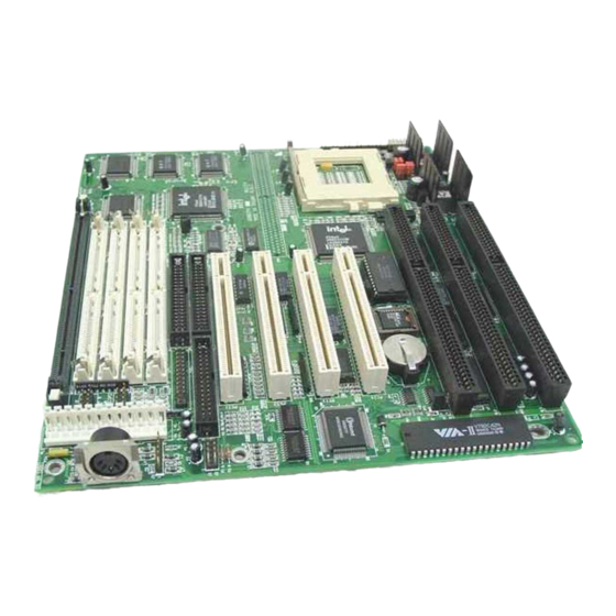
Page 6: Chapter 2: Hardware Installation
Chapter 2 Hardware Installation Board Layout I/O Chip Battery Intel SB82371SB Bank 1 Bank 0 Pin 1 square denotes pin 1 PBSRAM = Pipeline Burst SRAM... -
Page 7: System Memory
0 or Bank 1, but you must populate one bank first before going to the next bank. The G586IPV/E system board can support 8MB to 128MB of memory using 1MBx32, 2MBx32, 4MBx32, or 8MBx32 72-pin SIMMs. The table below shows the supported SIM modules and their corresponding memory sizes. - Page 8 Bank 0 Bank 1 SIMM2 Memory Size SIMM1 SIMM3 SIMM4 1MBx32 24MB 1MBx32 2MBx32 2MBx32 2MBx32 24MB 2MBx32 1MBx32 1MBx32 4MBx32 32MB 4MBx32 — — 2MBx32 2MBx32 32MB 2MBx32 2MBx32 1MBx32 4MBx32 40MB 1MBx32 4MBx32 4MBx32 1MBx32 40MB 4MBx32 1MBx32 2MBx32 2MBx32 4MBx32...
-
Page 9: Cache Memory
U23 of the system board. Refer to page 6 for the locations of the SRAMs. CPU Installation The G586IPV/E allows for easy installation of CPUs. Make sure all jumpers are set correctly before applying power or you may damage the CPU or system board. Please see the jumper settings on the following pages. - Page 10 Jumper Settings for Intel CPUs Intel CPUs Ext. Bus Pin 1-2 Pin 3-4 75MHz 50MHz 90/120/150MHz 60MHz 100/133/166/200MHz 66MHz Intel CPUs Freq. Ratio Pin 1-2 Pin 3-4 75/90/100MHz 1.5x 120/133MHz 150/166MHz 2.5x 200MHz Voltage 3.3V* 1-2 On 3.5V 3-4 On * Default Warning: The default setting of JP9 is 3.3V.
- Page 11 Jumper Settings for Cyrix 6x86 CPUs Cyrix CPUs Ext. Bus Pin 3-4 Pin 1-2 50MHz P120+ P133+ 55MHz 60MHz P150+ 66MHz P166+ Cyrix CPUs Freq. Ratio Pin 1-2 Pin 3-4 P120+/P133+/ P150+/P166+ Voltage 3.3V* 1-2 On 3.5V 3-4 On * Default Warning: The default setting of JP9 is 3.3V.
- Page 12 Jumper Settings for AMD-K5 CPUs AMD-K5 CPUs Ext. Bus Pin 1-2 Pin 3-4 PR75 75MHz 50MHz PR90 90MHz 60MHz PR100 100MHz 66MHz AMD-K5 CPUs Freq. Ratio Pin 1-2 Pin 3-4 PR75 75MHz 1.5x PR90 90MHz PR100 100MHz Voltage 3.3V* 1-2 On 3.5V 3-4 On * Default...
- Page 13 Installing Upgrade CPUs The G586IPV/E is equipped with a 321-pin Zero Insertion Force (ZIF) socket at location U25 of the system board. Refer to page 6 for the location of the ZIF socket. This socket is designed for easy removal of an old CPU and easy insertion of an upgrade CPU.
- Page 14 Lifting the Handle 2. Once the lever is completely up, remove the old CPU carefully by lifting it straight out of the socket. You are now ready to insert the new CPU. 3. Position the CPU above the ZIF socket. Make sure pin 1 of the CPU is aligned with pin 1 of the socket.
- Page 15 Positioning the CPU Above the ZIF Socket 4. Push the handle down until the handle locks into place. The top plate will slide forward. You will feel some resistance as the pres- sure starts to secure the CPU in the socket. This is normal and will not damage the CPU.
-
Page 16: Jumper Settings For Cmos Clear
Clearance Requirements Your CPU comes with a heatsink mounted on top. To maintain proper airflow once the upgrade is installed on the system board, the CPU and heatsink require certain space clearances. The clearance above the CPU’ s fan/heatsink must be at least 0.4 inches. -
Page 17: Built-In Ports
2-3 On: Mono (default) Built-in Ports The G586IPV/E system board is equipped with two serial ports, one parallel printer port, one FDD connector, two IDE hard disk connectors and one PS/2 mouse connector. Refer to page 6 for the locations of the built-in connectors and pin 1 of those connectors. - Page 18 Connecting the Parallel Printer Port Attach the DB-25 printer cable, which came with the system board, to connector J7 on the G586IPV/E system board. Make sure the colored stripe on the ribbon aligns with pin 1 of connector J7. Use a small nutdriver to mount the cable into a DB-25 cutout in the system chassis.
- Page 19 IDE Hard Disk Interface The G586IPV/E system board is equipped with two PCI IDE connectors that will interface four Enhanced IDE (Integrated Drive Electronics) hard disk drives. Note: Only Enhanced IDE hard drives or ATAPI CD-ROMs can be connected to the IDE interface.
-
Page 20: Installing Expansion Cards
Master mode. Installing Expansion Cards The G586IPV/E system board is equipped with 4 dedicated PCI slots and 3 dedicated 16-bit ISA slots. All PCI slots are bus masters. Refer to page 6 for the locations of the expansion slots. Due to the size of the CPU with its accompanying fan/heatsink component, the length of the add-in cards in PCI slot 4 and ISA slot 1 is limited to 18cm (7.07",... -
Page 21: Chapter 3: Software Installation
Chapter 3 Software Installation After you power up your system, the BIOS message appears on your screen and the memory count begins. After the memory test, the following message will appear on the screen: Press DEL to enter setup If the message disappears before you respond, restart your system or press the “... -
Page 22: Standard Cmos Setup
Use the arrow keys to highlight the option you want and press <Enter>. The following describes each of these options. Note: The settings of the BIOS setup screens on the following pages are for reference only. Some of the settings will vary according to your system’... - Page 23 Time The time format is <hour>, <minute>, <second>. The time is based on the 24-hour military-time clock. For example, 1 p.m. is 13:00:00. Hour Displays hours from 00 to 23 Displays minutes from 00 to 59 Minute Displays seconds from 00 to 59 Second Primary Master, Primary Slave, Secondary Master and Secondary Slave...
- Page 24 Drive type Type Number of cylinders Cyls Number of heads Heads Write precomp Precomp Landing zone Landzone Number of sectors Sectors Mode type Mode If a hard disk has not been installed, select None and press <Enter>. Drive A and Drive B These categories identify the types of floppy disk drives installed.
- Page 25 Enhanced Graphics Adapter/Video Graphics Array. For EGA, EGA/VGA VGA, SEGA, SVGA and PGA monitor adapters. Color Graphics Adapter. Power up in 40-column mode. CGA 40 Color Graphics Adapter. Power up in 80-column mode. CGA 80 Monochrome adapter. Includes high resolution monochrome Mono adapters.
-
Page 26: Bios Features Setup
BIOS Features Setup The BIOS Features Setup allows you to configure your system for basic operation. Some entries are defaults required by the system board, while others, if enabled, will improve the performance of your system or let you set some features according to your preference. ROM PCI/ISA BIOS BIOS FEATURES SETUP AWARD SOFTWARE, INC. - Page 27 Many disk diagnostic programs which attempt to access the boot sector table will cause the warning message to appear. If you are running such a program, we recommend that you first disable this category. Also, disable this category if you are installing or running certain operating systems like Windows 95 or the operating system may not install nor work.
-
Page 28: Boot Sequence
Boot Sequence This category determines which drive to search first for the disk operat- ing system (i.e. DOS). The default is A, C. A, C The system will first search for a floppy drive and then a hard disk drive. C, A The system will first search for a hard disk drive and then a floppy drive. -
Page 29: Security Option
Boot Up NumLock Status This allows you to determine the default state of the numeric keypad. By default, the system boots up with NumLock on. The function of the numeric keypad is the number keys. The function of the numeric keypad is the arrow keys. Security Option This category allows you to limit access to your system and Setup, or just to Setup. -
Page 30: Chipset Features Setup
Video BIOS Shadow Determines whether video BIOS will be copied to RAM. Video Shadow will increase the video speed. Note that some graphics boards require that this option be disabled. Video shadow is enabled. Enabled Disabled Video shadow is disabled. C8000-CBFFF Shadow to DC000-DFFFF Shadow These categories determine whether option ROMs will be copied to RAM. -
Page 31: Power Management Setup
ISA Bus Clock PCICLK/4 ISA bus clock frequency is equal to the PCICLK of your CPU divided by 4. PCICLK/3 ISA bus clock frequency is equal to the PCICLK of your CPU divided by 3. Note: Refer to the “ CPU Installation” section for the PCICLK of your CPU. Power Management Setup The Power Management Setup allows you to configure your system to most effectively save energy. -
Page 32: Video Off Method
Disable No power management. Disables the Doze, Standby and (default) Suspend modes. Min. Power Minimum power management. Doze Mode = 1 hr., Standby Saving Mode = 1 hr., Suspend Mode = 1 hr. and HDD Power Down = 15 min. Max. - Page 33 Standby Mode This Green PC power saving function is user configurable only when the Power Management category is set to User Defined. It is used to define the idle time that elapses before the system enters the Standby mode. When enabled and after the set time of system inactivity, the fixed disk drive and the video will be shut off while all other devices still operate at full speed.
-
Page 34: Pnp/Pci Configuration Setup
PNP/PCI Configuration This section describes configuring the PCI bus system. It covers some very technical items and it is strongly recommended that only experi- enced users should make any changes to the default settings. ROM PCI/ISA BIOS PNP/PCI CONFIGURATION AWARD SOFTWARE, INC. Resources Control By :Auto PCI IRQ Active By... -
Page 35: Load Bios Defaults
PCI IDE IRQ Map To This category is used to configure your system to the type of IDE disk controller in use. Designates which ISA slot is installed with an IDE controller card; that is, if you are using an IDE controller card. PCI-Auto The system will scan and determine the PCI slot that is in- stalled with an IDE controller card. -
Page 36: Integrated Peripherals
Integrated Peripherals ROM PCI/ISA BIOS INTEGRATED PERIPHERALS AWARD SOFTWARE, INC. IDE HDD Block Mode : Enabled IDE Primary Master PIO : Auto IDE Primary Slave PIO : Auto IDE Secondary Master PIO : Auto : Auto IDE Secondary Slave PIO : Enabled On-Chip Primary PCI IDE On-Chip Secondary PCI IDE... -
Page 37: Supervisor Password
Enabl e d The IDE controller card is designated as the secondary IDE controller. Disabled No IDE controller card occupying any of the PCI slots. Onboard FDD Controller Enabl e d Enables the onboard floppy disk controller. Disabled Disables the onboard floppy disk controller. Onboard Serial Port 1 and Onboard Serial Port 2 Auto Selects an address for the onboard serial port 1 and serial... -
Page 38: User Password
If you want to protect access to setup only, but not your system, set a supervisor’ s password with the “ Setup” option selected in the BIOS Fea- tures Setup. You will not be prompted for a password when you cold boot the system. -
Page 39: Ide Hdd Auto Detection
IDE HDD Auto Detection This option detects the hard disk parameters for the hard disk drives installed in your system. Highlight this option and press <Enter>. A screen similar to the one below will appear. ROM PCI/ISA BIOS CMOS SETUP UTILITY AWARD SOFTWARE, INC. - Page 40 The maximum number of cylinders, heads and sectors for Normal mode are 1024, 16 and 63, respectively. no. Cylinders (1024) x no. Heads ( 16) x no. Sectors ( 63) x bytes per sector ( 512) 528 megabytes LBA (Logical Block Addressing) Mode The maximum HDD size supported by the LBA mode is 8.4 gigabytes.
-
Page 41: Hdd Low Level Format
HDD Low Level Format The HDD Low Level Format utility is designed as a tool to save you time formatting your hard disk. It automatically looks for the necessary information of the drive you selected. This utility also searches for bad tracks and lists them for your reference. -
Page 42: System Error Report
Without Saving” and press <Enter>. The message below will appear: Quit Without Saving (Y/N)? N Type “ Y” and press <Enter>. The system will reboot and you will once again see the initial diagnostics on the screen. If you wish to make any changes to the setup, press <Ctrl>... -
Page 43: Ide Device Drivers
The checksum of ROM address F0000H-FFFFFH is bad. Memory test fail BIOS reports memory test fail if the memory has error(s). IDE Device Drivers To install the IDE drivers supported by the G586IPV/E system board, please refer to the “ Readme” file contained in the provided diskettes. -
Page 44: Appendix A: Types Of Modules
Appendix A Types of Modules The following modules have been tested with this board. Most untested brands will work but a few may fail to do so. SIMM Brand Chip Number 1MBx32 Fujitsu 81C1000A-70 M51440A-70 2MBx32 M511000B-70 424400-60 Micron 40447-60 TMS4400DJ-70 Micron MT4C4007-70 (EDO) -
Page 45: Appendix B: Memory And I/O Maps
Appendix B Memory and I/O Maps Memory Address Map Address Name Function 0000000 to 640KB System System Board Memory 009FFFF Board RAM 00A0000 to 128KB Video Reserved for Graphics 00BFFFF Display Memory Display Memory 00C0000 to 160KB I/O Reserved for ROM on 00E7FFF Expansion ROM I/O Adapter Card... - Page 46 I/O Address Map I/O Address Function 0000-001F DMA Controller 1, 8237A-5 0020-003F Interrupt Controller 1, 8259A, Master 0040-005F Timer, 8254-2 0060-006F 8742 (Keyboard Controller) 0070-007F Real-time Clock, NMI (Non-maskable Interrupt) Mask 0080-009F DMA Page Memory, 74LS612 00A0-00BF Interrupt Controller 2, 8259A 00C0-00DF DMA Controller 2, 8237A-5 00E8...
-
Page 47: Appendix C: Connector
Appendix C Connectors Connectors PS/2 mouse connector COM 1 serial port COM 2 serial port Floppy disk drive connector Parallel printer port Primary IDE hard disk drive connector Secondary IDE hard disk drive connector Fan connector HD LED connector Green LED connector Green button connector Reset switch connector Speaker connector... - Page 48 J13 - HD LED connector J14 - Green LED connector Function Function Signal Signal J15 - Green button connector J16 - Reset switch connector Function Function Ground Ground Reset Signal J17 - Speaker connector J10 - Fan connector Function Function Signal Ground N.
Need help?
Do you have a question about the G586IPV and is the answer not in the manual?
Questions and answers